1
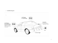
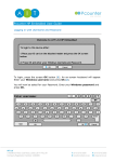
P1410
User Manual
866-805-6922
1
Contents
Note
Warning ------------------------------------------- 3
Product information
Introduction ----------------------------------- 4
Features and benefits------------------------- 4
Specifications --------------------------------- 4
How to use
Power---- --------------------------------------- 5
Display ----------------------------------------- 5
Volume Adjustment--------------------------- 6
Precautions ------------------------------------ 6
Sensing Range and Warning Method ------ 6
Notes ------------------------------------------- 7~8
Maintenance ----------------------------------- 9
How to install
Tools ------------------------------------------- 10
System Components ------------------------- 10
Installation diagram -------------------------- 11
Installation Procedure------------------------ 12
Installation of sensors------------------------ 12
Wire Connection ----------------------------- 13
Precaution during installation--------------- 14
Final testing ----------------------------------- 14
Troubleshooting ------------------------------ 14
Warranty------------------------------------------ 14
2
Note:
•
•
•
•
Please read this manual carefully before using this
product.
This system is designed to be an aid and should not
replace the need to drive carefully. Under no
circumstances will the manufacturer or supplier accept
any responsibility or can be held liable for any direct or
indirect, incidental or consequential damage, or for
injuries resulting from installing or use of this system..
Manufacturer or supplier does not warrant the accuracy
or completeness of the information in this documentation
and manufacturer or supplier reserve the right to alter
specifications without notice.
To the extent permitted by law, manufacturer or supplier
exclude all liability, including negligence for any loss
incurred in reliance on the contents in this publication.
Warning:
•
•
•
Please practice reverse parking using different
obstacles to test this product’s performance.
Though the minimum detecting distance is 1.15 feet,
it is still recommended to keep enough space to stop
the car. Considering the cars’ inertia, it would be
better to stop the car when the distance is shorter than
2 feet.
The reverse speed should be less than 3 miles / hour.
3
Products information
•
Introduction
The system alerts the driver the distance of obstacles while
reversing the vehicle. It includes 4 sensors, 1 waterproof
controller and 1 display. The system generates both audible
and visual warning.
•
Specifications
1. Operation voltage:
2. Power consumption:
3. Operation temperature:
4. Detection distance:
5. Display resolution:
6. Detecting error:
7. Detecting rate:
DC 10V ~ 16V
< 4W
-35°C ~ +70°C
1.15 ~ 8.00 feet
0.01feet
+/-0.06 feet
4 times/sec
•
1.
2.
3.
Features and benefits
Accurate measurement and stable readout
High sensitivity, wide detection range and small blind area.
Functions include digital display / sound alarm / zone &
direction indication / reverse reminder / Self-testing. The
outfit of display unit matches the instrument panel of car.
4. Applicable to most cars and easy installation.
4
How to use
•
Power
The system is automatically activated when the reverse gear
is engaged. Self-testing program will be done right after the
system is powered on. After the buzzer beeped and the
direction indicators on, the system is ready.
The LCD unit is plugged into black receiver box and this
receive box must be tapped into a constant 12 volt source in
the front of the vehicle.
•
Display
P1410 display unit
Sound Alarm
Zone Indication
1.28 ----- Distance between sensor and obstacle.
Distance Display
Direction Indication
P-1410 Display
----- Indicate the closest obstacle direction using
flashing LED or icon.
----- Indicate zone stage with a pointer or car icon.
5
•
Volume Adjustment
There are 10 volume levels. The toggle switch can
be moved to the right and left, pushing to the right
will increase volume and to the left will decrease,
down to mute.
•
Precautions
2
3
Danger zone start 2 feet away from obstacle
Reverse speed should be less than 3 miles / hour to avoid
accidents and give you a chance to respond to backup sensor
Thin and small obstacles can be detected at shorter range only
6
•
Sensing Range and Warning Method
Distance Display
1.15
8.00
Green
light
Yellow
Light
Red
light
Zone Indication
Sound Alarm
Distance (feet)
No
Sound
Sound with
Long Intermit
Sound with
Short Intermit
Rapid
Sound
Safe Zone
Warning Zone
Dangerous Zone
8.00
5.00
2.00
Continuous
Sound
1.15
0
7
•
Notes
Please check the condition behind your car before reversing.
In some cases, the display may be not as same as the reality
due to the sensor position, obstacle shape, reflection condition
and so on. Some examples are given below.
3. Though A is closer to the car than B, the distance from sensor
to point B is shown.
1. As B is under the level of sensors, and A is a strong reflecting
point, the distance of CA will be shown first. When the
obstacle is within the blind area, both A and B will not be
detected. This will occurs when the obstacle is lower than the
level of sensors.
4. In case of small angle of incidence to the obstacle, such as
glass or other smooth plane, the obstacle is not detected.
2. Due to obstacle A is pretty short, so during reversing, the
distance between sensor and obstacle A shown first. After
obstacle A is within blind area, the distance between sensor
and obstacle B will be shown.
8
5. B will be detected sooner or later, but A may not be detected
at all.
8. Not all obstacles is detected from 8 feet. for instance, a person
is detected from 4.26 feet because of the weak reflection of
clothes.
7.2
3.9
6. The reading may moves up and down between 3.9 feet and 7.2
feet because the low obstacle A is at the critical detecting
point. The reading will be stable after a little bit closer to the
obstacle A.
9. The distance form sensor A to B, rather than C to D, is shown.
•
Maintenance
(1) Clean up the sand, ice, snow or any other dirt on sensors’
surface timely.
(2) Re-paint is allowed on sensors’ surface with slight coat.
However, extra thick paint may affect detection.
7. On certain conditions, for example, in case of rough ground,
ground might be detected instead of object “A”.
4.26
9
How to install
•
Tools
•
System Components
10
•
Installation diagram
1410 Display
rear positioning
Controller
No wires from
Controller to LCD
1410 Display
Front positioning
Must power front
LCD to constant 12
volt source
Sensor
Reverse Light
11
•
Installation procedures
.
Sensor positioning
Interval of sensors
Sensors are installed on the position
in accordance with the diagram
Mirror symmetry
horizontally
Display unit installation
Plug display unit into its pedestal
and adjust it to suitable position.
The mounting surface must be clean.
•
Drill-holes
wiring
Make holes in bumper
with included drill bit
Making connections with
assistant tools. Make sure the
recessed sensor surface facing
upwards slightly while keeping
the whole sensor body
horizontally
Connection
Test
Connect the controller to
+12V power supply, sensors
To check if the parking
assistance system works
properly.
Controller installation
The position of controller
should be appropriate to
both sensors
.
Installation of sensors
(1) Horizontal position
X=0.66~0.98 feet
Same height, equally distributed
12
H=1.64~2.30 feet
(2) Vertical level
The surface to install sensors need to be
vertical and flat
Connect the red wire of controller to the reversing light’s positive,
and the black to the negative. The wiring card usage refers to the
following diagram.
.
(3) Direction of sensor
Note: The E-shape contact must be fully pressed.
•
Wire Connection
13
•
1. Do not scratch the surface of bump during drilling
holes
2. Do not cut or damage the wire in any circumstance.
3. Make sure the power cable is connected correctly. The
controller should be secured in a water proof location.
4. The surface to mount the display must be clean
5. Make sure all the connection is correct before final
testing; Any problem could refer to the “Trouble
shooting” section
•
•
Precaution during installation
Troublehooting
Problem
No display
during
reversing
Wrong
orientation
indication
Constantly
display
“—p—“
Display a fixed
distance
Final testing
1. Use one selected object to test the sensing distance and
warning as stated in page 7
2. Use one selected object to check if each sensor is in
the right position.
3. If the system detected something which is not existed,
adjustment is needed for the controller. (peel off the
“QC” label in the back of controller, screw
anticlockwise until the signal cleared out)
Orientation
indicator not
on
Possible Causes
a. No power
b. Display unit is not
connected to
controller properly
The sensor’s position is wrong
Resoluton
Make sure all the
connection is
correct
An object within 0.89foot is
detected all the time
Adjust the sensors’
position or angle
a. Ground is
detected
b. Sensors’ direction
is wrong
Sensor’s connector is not
plugged in properly or is
plugged in while power is on
Adjust the sensors’
position or
direction
Change sensors’
position
Check if the
connector is firmly
connected
Then witch on
power again
Warranty
•
•
1 year
Any physical damage will void the warranty
14