1
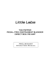
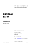
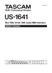
UTA UnderToneAudio MPDI-4 User Manual Version 1 1. INTRODUCTION2 2. SAFETY/POWERING UP3 3. RACK MOUNTING6 4. AUDIO CONNECTIONS7 5. FRONT PANEL CONTROLS8 6. HARMONIC COLORATION10 7. MIC PRE EXAMPLE SETTINGS 11 8. THE DI (DIRECT INPUT) 13 9. SPECIFICATIONS14 1 1. INTRODUCTION Congratulations! You are the proud owner of the UTA MPDI-4: a wonderfully flexible, beautiful sounding Class A Mic Preamp/DI. The MPDI-4 packs a huge amount of Class A audio power into a single rack unit. To get up and running right away with your MPDI-4, skip to Chapters 2 (Powering Up), 3 (Rack Mounting), and 5 (Front Panel Controls). The most vital information about the proper installation of the MPDI-4 in this manual is in Chapter 3 (Rack Mounting). The rest of the manual contains more detailed information that is not essential for understanding the unit’s basic functionality. The mic preamp has gone through exhaustive recording, listening, and analytical tests to end up with the best possible combination of components and features. The goal was to have something that could give the vintage musicality one would be accustomed to with a Neve or EMI pre, but still retain the option of running the mic pre cleaner when needed. We came up with a design wherein the user has extraordinary control over the sonic character of the mic preamp by making it possible to bypass either or both of the transformers, change the overall headroom of the output stage, and alter the THD (total harmonic distortion) signature of the circuit. This flexibility now makes the UTA pre the first pick for almost every recording situation. There is also a user switchable low impedance mode that changes the strapping of the input transformer. This mode performs extraordinarily well with passive ribbon mics. We now use the UTA mic pre exclusively with all of our ribbon mics. The DI input was optimized for passive guitars and basses. Its exceptionally high input impedance and Class A circuitry make it the perfect choice when capturing passive instruments either for the purpose of re-amping or if you want to use the DI signal itself in the mix. 2 2. SAFETY/POWERING UP SAFETY INSTRUCTIONS WARNING: To reduce the risk of fire or electric shock, do not expose this product to rain or moisture. CAUTION: RISK OF ELECTRIC SHOCK. DO NOT OPEN. There are no user serviceable parts inside the product. Refer servicing to qualified service personnel. In order to ensure safe operation of the device, follow these guidelines: 1. Read the instruction manual in its entirety before operating the equipment. Retain the manual for future reference. 2. Observe all safety precautions, warnings and instructions noted in this manual. 3. Always unplug this device from the wall socket before cleaning. Use only dry cloth. Do not use aerosols or solvents. 4. Keep this device away from sources of water such as pools, bathtubs and sinks, and do not expose it to rain or splashes of water. Do not place objects filled with fluid on the device. 5. Vents are provided for heat dissipation on the sides and the rear of the device. Maintain at least 2” (5cm) space around these vents to provide sufficient ventilation. 6. Keep the device away from sources of heat and open flame such as heaters, radiators, stoves, lit candles, etc.. 7. Make sure the power cord is intact before plugging it into the device. Do not use cords with visible damage to the insulation or connectors. 8. This device is equipped with a safety feature that requires the use of a three-‐pin grounding power plug. Do not defeat the safety purpose of the grounding plug. If the provided plug does not fit your outlet, consult an electrician to replace your obsolete power outlet. 9. Use only accessories listed in this manual or otherwise specified by the manufacturer. 10. Do not install this product on carts or other moving objects. 11. When the device is in use, route the power cord in such a way that will prevent it from being stepped on, tripped on, pinched or damaged. 3 12. Do not use this device with wall or ceiling mounts not specified by the manufacturer. 13. To completely disconnect the device from the AC Mains, disconnect the power cord from the AC receptacle. For additional protection, unplug the device during electrical storms, or when not used for long periods of time. 14. No user serviceable parts inside. Refer servicing to qualified personnel. If the unit was exposed to liquid, excessive heat or fire, or sustained mechanical damage of any kind, do not attempt to operate it. Disconnect the unit from the wall outlet and consult qualified service personnel. INSTRUCTIONS FOR 220-‐240VAC OPERATION 1. Before proceeding, disconnect the power cord from the AC inlet. 2. This device is provided with a power cord for North American 110-‐120VAC operation. For operation in other locations and/or from other voltage sources, use the correct type of power cord for your area and voltage source. 3. This device is provided with T 0.4A AC Mains fuses installed for 110-‐120VAC operation, and includes T 0.2A accessory fuses for 220-‐240VAC operation packed separately. Open the fuse drawer on the AC receptacle on the rear of the device and replace the T 0.4A fuse with the T 0.2A accessory fuse. 4. In the fuse drawer, change the AC Mains switch from the 110V position to the 240V position. 5. Assure that the fuse drawer is secured closed before attaching the power cord. INSTRUCTIONS POUR 220-‐240VAC FONCTIONNEMENT 1. Avant de commencer, débranchez le cordon d'alimentation de la prise secteur. 2. Cet appareil est fourni avec un cordon d'alimentation pour l'Amérique du Nord 110-‐ 120VAC 60 Hz. Pour une utilisation dans d'autres endroits et / ou d'autres sources de tension, utiliser le bon type de cordon d'alimentation de votre région et source de tension. 3. Cet appareil est fourni avec T 0.4A AC Mains fusibles installés pour une opération de 110 120 V ca, et comprend T 0.2A accessoires fusibles pour un fonctionnement 220-‐ 240VAC emballés séparément. Ouvrez le tiroir du fusible sur la prise secteur à l'arrière de l'appareil et remplacer le fusible de 0.4A T avec l'accessoire fusible T 0.2A. 4. Dans le tiroir de fusible, changer les secteur CA passer de la position 110V à la position 240V. 5. Assurez-‐vous que le tiroir à fusibles est fixé fermé avant de fixer le cordon d'alimentation. 4 POWERING UP Picture 1 Before you connect the AC power cable, check to make sure the AC operating voltage on the unit is set to properly match the voltage of your AC outlets. The options are 110 V (appropriate for 110 V - 120 V range) or 240 V (appropriate for 220 V - 240 V range). The operating voltage of the MPDI-4 can be changed by removing the small tray in the power entry module. Simply flip around the small PCB inside the tray so the correct voltage is showing in the window when the tray is re-inserted in the power entry module. When changing the MPDI-4 to a different operating voltage, you must also change to the appropriate fuse value to be sure it is either Picture 1 shows the MPDI-4 set in the 110 V properly protected, or won’t immediately blow the fuse (see Picture mode. This will work for voltages from 110 V - 120 V 1 or 2 for appropriate fuse values). PLUGGING THE MPDI-4 INTO A 220 V- 240 V OUTLET WHEN SET FOR 110 V OPERATION WILL LIKELY RESULT IN DAMAGE TO THE POWER SUPPLY OF THE UNIT Picture 2 AND REQUIRE SENDING IT BACK TO UTA FOR REPAIR!!! Once you have confirmed that the operating voltage is set correctly, make sure the power switch is in the “OFF” or “OUT” position. Plug the supplied IEC AC power cable into the AC power receptacle on the back of the unit. Plug the other end into an appropriate grounded AC outlet. You are now ready to power up the unit. Simply push the power switch on the front panel to the “ON” or “IN” position. When the MPDI-4 is powered you will see the VU meter jump around for a couple of seconds. This is normal. The illumination of the VU backlight LED is the indication that the MPDI-4 is powered up and ready for use. The MPDI-4 is protected by a “slow blow” or time delay fuse. The fuse can be found mounted in the removable tray (see Picture 3). There is also a small compartment that holds a spare fuse. The spare fuse is a T0.4A fuse for 110 V operation. If the MPDI-4 blows a fuse, it is best to first try to determine what caused the fuse to fail before installing the spare. Once the cause for failure has been resolved, install the spare fuse and you are ready to go! Picture 2 shows the MPDI-4 set in the 240 V mode. This will work for voltages from 220 V - 240 V Picture 3 Picture 3 shows the fuse tray and the hidden spare fuse housing Picture 4 Picture 4 shows the PCB voltage selector 5 3. RACK MOUNTING As you have seen repeatedly in this manual, the MPDI-4 is a Class A device. Class A circuitry unavoidably generates heat. How one chooses to rack-mount these devices can have a significant affect on the ambient temperature inside the enclosure. We have done everything we can (short of using a fan) to improve the thermal performance and we have put them through “worst case” rack mounting scenarios to make sure that they will perform reliably under those conditions. However, we just want to make people aware of how the various rack mounting options will affect the thermal performance. THE WORST POSSIBLE WAY TO MOUNT MULTIPLE MPDI-4s IN A RACK, IS TO STACK THEM ONE ON TOP OF EACH OTHER. When three MPDI-4s are stacked on top of each other in a rack, the one in the middle will maintain an average internal ambient temperature of about 120˚F (49˚C). If you stack 6 of them, the middle units can get up to 130˚F (54˚C), 8 of them can get over 140˚ F (60˚C). The MPDI-4 is protected by thermistors. When the units get in the 140˚F (60˚C) range, the thermistors will start to shut down the various DC voltages. THIS IS VERY IMPORTANT!! IF THE LIGHT IN THE VU METER TURNS OFF AND/OR THE MPDI-4 STOPS PASSING AUDIO WHILE THE POWER SWITCH IS TURNED ON, THAT MEANS THAT A THERMISTOR HAS TRIPPED BECAUSE THE UNIT IS RUNNING TOO HOT!! Simply turn off the MPDI-4, change the rack mounting situation such that it allows the unit to run cooler and then power it back up. Everything should be fine. The thermistors will reset themselves after the unit cools down and if the new rack mounting arrangement keeps things cool enough, it will not happen again. The temperature at which components inside the unit would start to actually burn up is around 220˚F (105˚C). We are a long ways away from that, but there is a catch: the closer you get to that temperature, the shorter life span the internal components will have. WE STRONGLY RECOMMEND LEAVING A GAP BETWEEN EACH MPDI-4 MOUNTED IN A RACK. If you mount the MPDI-4 with even just a 1/3 of a rack space between each unit, the average internal ambient temperature will be 105˚F - 115˚F (41˚C- 46˚C). An MPDI-4 sitting by itself in a rack will maintain an average internal temperature of about 100˚F (38˚C). Here is the crazy thing, if you mount an MPDI-4 vertically, the average internal temperature drops as low as 80˚F(27˚C)!!! It turns out that the standard the world has chosen for orienting rack mount equipment (horizontally) SUCKS for thermal dissipation. If you have the option of mounting the MPDI-4 vertically it is unquestionably the best way to do it (this is also true for most all rack mounted gear). At the end of the day, keeping the internal temperature of the MPDI-4 lower will most likely give it a longer life span. How much longer? Well, we are not really sure. We expect the MPDI-4 to function without any need for service for about 15 years. Will stacking these on top of each other in a rack shave off 1, 2 or 3 years from that expectation? We just won’t know for sure for about 10-15 years from now. We recommend mounting the units in a way that will keep them as cool as possible, whenever possible. 6 Chassis Gnd MPDI-4 Serial # Designed and built in California by Undertone Audio Inc. 4. AUDIO CONNECTIONS EW #1 COMPLETED PART REAR AUDIO INPUTS/OUTPUTS Picture 5 4 Mic Out Mic In 3 Mic Out Mic In 2 Mic Out Mic In 1 Mic Out Mic In R Lift Chassis Gnd MPDI-4 Serial # Designed and built in California by Undertone Audio Inc. OMPLETED PART WITH CONTROLS MIC IN REAR (x4) - These are one of 2 input connectors available for getting signal into the mic preamps. The rear mic inputs are convenient to use if the MPDI-4 is rack mounted and wired to a patch bay. The rear mic input connectors will automatically be disconnected as soon as an XLR or 1/4” cable is plugged into its REVISION HISTORY: corresponding front Mic/DI input jack. revB - changed vent hole pattern on left for safety co revB2signal - made and built...” larger and bold MIC OUT (x4) - These male XLR connectors give you access to the output of“Designed the mic preamp. revB3 - made “risk of electric shock” bold revB4 - inverted “risk of electric” shock graphic to ma FRONT AUDIO INPUTS OFF -60 -55 OFF -50 0 48V LOW OFF NoX 180 -45 -40 HI -20 PH Xfrmr LOAD OUT OUTPUT 4 -10 MIC GAIN OFF -50 0 48V LOW HI -20 OFF NoX PH 180 -45 -40 -30 -25 -20 -15 NoX -10 MIC GAIN -35 OFF OUT OUTPUT 3 -30 -25 HI -20 180 -45 -40 -30 -25 48V LOW Xfrmr LOAD -35 -50 0 PH -60 -55 -10 MIC GAIN -60 -55 OUT OUTPUT 2 -35 -30 -25 -60 -55 Xfrmr LOAD -20 180 -45 -40 -35 -50 PH -15 -10 MIC GAIN -20 1 -15 OUTPUT 0 Xfrmr LOAD OUT HI -20 OFF -15 MIC/DI IN (x4) - These Neutrik combo jacks allow you to plug either a male XLR or a 1/4” instrument connector directly into the front of the unit. When a male XLR connector is plugged in, the combo jack automatically switches to only allow signal from the front “MIC IN” jack to go to the mic preamp. When a 1/4” jack is plugged in the combo jack automatically switches the circuitry to function as a Class A DI and also disconnects the rear “MIC IN” jack. 7 OFF 48V LOW -20 Picture 6 NoX 5. FRONT PANEL CONTROLS -10 PH Xfrmr LOAD 180 OUT 12 OUTPUT 4 MIC GAIN -45 -40 -30 -25 -60 -55 -35 -50 HI -15 NoX 1 2 0 1 3 Meter 4 48V LOW HI -20 2 OFF -20 OFF V LOW F 9 10 11 Picture 7 frmr LOAD OUT 8 OFF UTA NoX 3 4 5 MPDI - 4 6 7 DESCRIPTION OF FRONT PANEL CONTROLS 1. FRONT MIC AND DI INPUT - This combo jack input allows you to plug either a microphone cable or 1/4” instrument cable directly into the front of the unit. Plugging a mic cable into the front mic input automatically disables the rear mic input. Plugging in a 1/4” instrument cable allows you to use the MPDI-4 as a DI. When a 1/4” cable is plugged in, both the front and rear mic inputs are disabled. 2. MIC GAIN - This rotary switch allows you to adjust the amount of gain on the mic pre from -10 dB to -60 dB in 5 dB steps. 3. PAD - This toggle switch engages the passive -20 dB pad before the mic pre. There is no padding when the switch is in the up or “0” position. -20 dB of padding is added when the switch is in the down or “-20” position. 4. 48V/OFF - This toggle switch turns on or off the 48 V “phantom power”. Turn this on when using microphones that require “phantom power” to function. Turning the 48 V “phantom power” on or off can cause a very loud low frequency “thump” to come out of the mic pre. Make sure you turn down your monitors or headphones when changing the 48 V setting. NOTE: Some ribbon microphones can be damaged by “phantom power”. It is always best to turn off the phantom power before plugging in any type of passive ribbon mic. 8 5. LOW/HI/NoX - This 3 position toggle switch selects the transformer mode for the input of mic preamp. LOW - In the “UP” or “LOW” position, the input transformer is configured for a low impedance high gain input. This setting works especially well for passive ribbon microphones. You will typically get an added 3 or 4 dB of gain with no additional amplifier noise. It also has sonic benefits as well. We have found the ribbon mics to sound clearer and more balanced in this mode. HI - This mode is best if you want to add input transformer coloration while using either dynamic or condenser type microphones. NoX - This mode removes the input transformer from the input of the mic preamp. It will give you the same input impedance and gain as the “HI” mode. This offers a unique opportunity to hear a transformerless Class A mic preamp. It is a stunningly pristine sound and is ideal for any recording that needs the highest degree of clarity and detail. NOTE: switching to or from the “NoX” mode will cause a loud low frequency thump (similar to turning the 48V on/off). Be sure you have your speakers or headphones turned down whenever switching to or from the transformer-less mode. 6. VU METER - This is a VU meter that will show the level being sent from any one of the 4 mic pre amps 7. POWER BUTTON - This push button turns on or off the power for the MPDI-4. In the “IN” position, the power is turned on. In the “OUT” position, the MPDI-4 will be powered off. The LED light illuminating the VU indicates if the MPDI-4 is turned on or off. 8. “-10” BUTTON - This push button engages the -10 dB output pad. It is actually a tiny bit less than -10 dB (about -9.6 dB). The button is changing the ratio of the output transformer to cause the drop in level. THIS OUTPUT PAD ONLY FUNCTIONS WHEN THE OUTPUT TRANSFORMER IS ENGAGED. We chose to do the PAD with the transformer instead of doing it resistively because it makes the output less susceptible to loading or long cable runs when the pad is engaged. You can use the output pad knowing that the sound of the device will not change or be compromised in any way. 9. PH/180 - This toggle switch allows you to reverse the polarity of the signal coming out of any one of the mic preamps. THE PHASE REVERSE ONLY FUNCTIONS WHEN THE OUTPUT TRANSFORMER IS ENGAGED. The phase will be the same as the incoming signal when the “UP” or “PH” position. The phase will be reversed 180 degrees from the incoming signal when in the “DOWN” or “180” position. 10. Xfrmr/OUT - This toggle switch allows you to have the output transformer either added or removed from the output signal. When the switch is in the “Up” or “Xfrmr” position, the output transformer will be added to the output signal and add all of the output transformer related functions (output pad & phase reverse). When in the “DOWN” or “OUT” position, the output transformer will be removed from the output signal and neither the output pad or the phase reverse will function. 11. LOAD/OFF - This toggle switch turns on or off the optional 600 Ω Load on the output. In the “UP” or “LOAD” position, the load is added. In the “DOWN” or “OFF” position, the 600 Ω Load is removed. The 600 Ω Load adds additional harmonic coloration that can sound very musical in certain situations. 12. Meter - This Rotary switch selects which of the 4 mic preamps are sending signal to the VU meter. 9 6. HARMONIC DISTORTION OK SO WE KNOW, WE KNOW!!! There are a lot of switches on this mic preamp. What can we say... we like gear that gives us a lot of control over the sound. We will do our best to give you simple starting point settings that will make it easy to get great results right away. First, a little more detail about the intention and function of the 4 features that control the Harmonic distortion character of the MPDI-4. These are the “Load” switch, the “-10 dB output pad” button, the “LOW/HI/NoX” and the “Xfrmr/OUT” switch. THE “LOAD” SWITCH - While using MPEQ-1s over the past couple of years, we noticed a difference in the sound when we plugged in a compressor after the MPEQ-1 that had a 600 Ω input impedance (UA 1176, LA2A, Pultec, etc.) This basically means that a 600 Ω load is being applied to the output stage of the MPEQ-1. The harmonic distortion character changed and – for certain things – it was a very desirable effect. We ultimately made some 600 Ω adapters that we could use when we wanted the load but weren’t using a 600 Ω device after the MPEQ-1. We then realized that it would be easy and very useful to make it a switchable feature on the front panel of the MPDI-4. The UTA mic preamp is capable of astonishingly low harmonic distortion performance. With both transformers bypassed and no load applied, the mic preamp will pass +27 dBu with only .003% THD. That is insanely low, especially for a Class A preamp. For all practical purposes, that is essentially NO audible distortion. However, while technically impressive, low distortion may not always sound the most musical. Many popular vintage mic preamps have much higher harmonic distortion signatures, as much as 20 or 30 times the distortion of the MPDI-4. The “LOAD” switch puts the UTA mic preamp into the same harmonic distortion range as many of the vintage preamps. There are other differences as well. It emphasizes the low order part of the THD and has a softer transition into clipping. With the “LOAD” switch off, the harmonic distortion has a “crunchier” quality to it where you mostly hear it clipping on the transients while the level is pushed. With the “LOAD” switch on, the harmonic distortion has a thicker, smoother, softer quality that can add a nice high frequency energy to a sound. It is important to know that using the “LOAD” switch will change how the output of the MPDI-4 interacts with other devices. If the “LOAD” switch is on and the output is plugged directly into a device that also has a 600 Ω input (UA 1176, LA2A, Pultec etc.), you will experience an additional increase in harmonic distortion and a further loss of headroom. THE “-10 dB OUTPUT PAD” - We have always used the UTA preamps with a UTA console. This allowed us to push the gain of the preamps and pad the signal with a fader or line trim control prior to sending the signal to a DAW or a tape machine. We know that many people will plug their mic preamps directly into the input of their A/D converters. This presents a problem: it is impossible to push the level of the mic preamps with out digitally clipping the signal. The -10 dB output pad addresses this issue. You can now drive the mic preamp as hard as you want and the peak level in the DAW will never exceed -2dBFS. It is important to know that our DAW system is calibrated to the standard reference level of 0 dbVU = -18 dBFS to achieve this result. THE “LOW/HI/NoX” and “Xfrmr/OUT” SWITCHES - Both the input and output transformers are bypassable on the MPDI-4. The transformers have a slight “smoothing” effect to the high frequency transients that makes things sound a bit less “pointy”. Overall the high end will sound a bit “smoother”. There is also a very subtle compression effect that occurs when the core becomes saturated with low frequencies, making the overall level of all the frequencies will drop very slightly. You will also experience a slight “thickening” of the sub frequencies when the transformers are engaged. As you can see, the combination of the “LOAD”, the “OUTPUT PAD”, and the “input/output Transformers” offer a huge variety of tonal options for the mic pre. Some are very subtle and some not-so-subtle. Experiment with the options to find a combination that works best for your taste and style of music. In the next section, we will give you presets that act as a good starting point to get the desired musical results. 10 7. EXAMPLE SETTINGS PRESET #1 - MAXIMUM COLORATION or “THAT 60’s SOUND” We are a huge fans of the sound of recordings made in the 60’s. When you listen carefully to these recordings, be it British Rock or Motown you will notice A LOT of distortion. Back then, they were doing everything possible to minimize noise and distortion, but the limitations of the gear unavoidably resulted in significant amounts of it and in most cases, it sounded awesome! The preset below will allow you to add as much distortion and coloration as you like without risk of clipping your converters. Picture 8 -10 MIC GAIN 180 -45 -40 OUTPUT 2 MIC GAIN OUT OFF -60 -55 48V LOW -30 -25 0 -45 -40 -35 -50 -30 -25 -60 -55 Xfrmr LOAD IN -35 HI -20 -20 -15 -50 PH OFF -20 OUTPUT 1 NoX -15 As you can see in “Picture #8”, we have highlighted the controls that are important. The “-10” output pad is engaged, the “Xfrmr” output transformer is engaged, and the “LOAD” is turned on. The input transformer should also be engaged but make sure to choose the impedance that best matches the microphone you are using (see item #5 on Page 10). The other controls can be set to accommodate your specific recording setup and circumstances. PRESET #2 - ROCK COLORATION or “THAT 70’s SOUND” As you get into the 70’s, you start to see equipment that has more head room like the API, QUAD 8, and NEVE circuits. There are still lots of transformers in the path as well as a higher overall THD. Picture 9 -10 MIC GAIN 180 OUTPUT 2 MIC GAIN OUT OFF 48V LOW HI -20 -15 -20 OFF NoX -15 “Picture #9”, shows that the “Output Pad” is now in the “OUT” position. The “LOAD” switch is on and both the input and output transformers are still engaged. This combination will get you similar results to using a Vintage Class A preamp (Neve 1073 or 1272, EMI TGI, Helios, etc.) It is a hard hitting sound with a bit of smoothing in the high frequencies. 11 -30 -25 -30 -25 0 -45 -40 -35 -50 -60 -55 -45 -40 -60 -55 Xfrmr LOAD OUT -35 -50 PH -20 OUTPUT 1 PRESET #3 - MODERN CLASS A This combination of settings gives you transformer coloration combined with maximum headroom and minimum THD in the active circuitry. It is great for recording applications that require a higher degree of clarity and detail. The transformers will still add a subtle amount of smoothness to the top end. Picture 10 -10 MIC GAIN 180 -45 -40 OUTPUT 2 MIC GAIN OUT OFF -60 -55 48V LOW -30 -25 0 -45 -40 -35 -50 -30 -25 -60 -55 Xfrmr LOAD OUT -35 HI -20 -20 -15 -50 PH OFF -20 OUTPUT 1 NoX -15 As you can see in “Picture #10”, we have highlighted the controls that are important for this setting. The output pad is not engaged, the output transformer is engaged and the LOAD is turned off. The input transformer should also be engaged but make sure to choose the impedance that best matches the microphone you are using (see item #5 on Page 10). The other controls can be set to accommodate your specific recording setup and circumstances. PRESET #4 - CLASS A TRANSFORMERLESS This combination of settings creates a circuit that (as far as we know) has never been available before. A balanced Class A mic preamp with excellent common mode rejection that is totally transformerless. With a THD of .003% at +27dBu, no crossover distortion, and phase linearity well beyond 50kHz, it could possibly be the most accurate preamp ever created. It is a stunningly pristine sound. This setting is ideal for situations where the highest degree of detail and clarity are essential. Picture 11 -10 MIC GAIN 180 OUT MIC GAIN OFF 48V LOW -30 -25 -30 -25 0 -45 -40 -35 -50 HI -20 -15 -20 OFF NoX -15 “Picture #11”, shows that the “Output Pad” is in the “OUT” position. The “LOAD” switch is “OFF”, and both the input and output transformers are BYPASSED. 12 OUTPUT 2 -60 -55 -45 -40 -60 -55 Xfrmr LOAD OUT -35 -50 PH -20 OUTPUT 1 8. THE DI (DIRECT INPUT) The DI was optimized for use with passive guitars and basses. We were looking to make a DI that would sound as transparent as possible for the purpose of re-amping. This DI achieves this better than any others we have used. It sounds as close to plugging directly into your amp as you can possibly get. The function of a DI is pretty straight forward: it is an impedance matching stage. The output impedance of a passive guitar or bass is typically quite high, usually in the 1 MΩ range. The input impedance of mic-preamps is typically much lower, usually in the 1 kΩ range. Why is that a problem? Well, if you plugged a guitar or bass directly into a mic preamp without any impedance matching stage, the interaction of those impedances, capacitances, and inductance of the pick ups would make the instrument sound like it was coming over a telephone. Impedance matching is EXTREMELY IMPORTANT. There are two main ways to create this impedance matching stage. One can do it passively (with a transformer) or actively. Each approach has their advantages and disadvantages. We chose to go the active route because, it offers the most sonic flexibility. It can be extraordinarily transparent or more colored depending on the various settings of the mic preamp. The trade off is that we give up the option of being able to lift the ground of the signal plugged into the DI. This can become an issue when using the DI for synths and drum machines. It is possible to experience a ground loop that causes hum under these circumstances. The best solution is to lift the ground (XLR Pin 1) on any/all outputs of the MPDI-4 being used. This can easily be done with XLR ground lift adapters (ex. Hosa GLT-255). When you plug into the 1/4” jack of the front panel combo input, an active Class A JFET stage is automatically added before the mic preamp. This stage creates the exceptionally high input impedance of 4.7 MΩ for the 1/4” input and subsequently a lower output impedance that is fed directly to the input of the mic preamp stage. The high input impedance reduces any interactions with the passive circuitry of your guitar or bass that can cause undesirable tonal changes. The Class A circuitry maintains sonic transparency. Tonal coloration can then be added in the mic preamp stage if desired. EXAMPLE SETTINGS There are two basic ways we like to use the DI. One capturing the DI signal for the purpose of re-amping a guitar or bass. The other is when the DI signal is intended to be used as the final sound. RE-AMPING -25 -2 0 OUT 0 OFF 48V LOW HI -60 -15 -55 -5 0 -20 OFF NoX DI COLOR OUTPUT -10 MIC GAIN -45 -40 180 OUT 48V LOW HI -20 -20 2 -30 -25 0 OFF In situations where the DI signal is intended to be used OUTPUT PH onXfrmr -10 turn as the final sound, we will typically bothLOAD transformers. From there you MICcan turn on the “LOAD” and/or the “-10 OUTPUT PAD”GAIN to add more coloration. This can OUT OFF 180 -45 -DI 40 bass, synths or drum mabe great when recording -50 chines (although see paragraph 3 this page about potential 0 48V LOW grounding issues with synths and drum machines.) -35 -30 -25 -60 -55 Xfrmr LOAD IN -35 -50 PH -15 1 2 OFF NoX 10 3 -30 -25 -40 -3 5 -15 -45 180 OUT When re-amping, it is best to use the setting that is the OUTPUT PH both LOAD Xfrmr transformmost transparent. This setting-10 bypasses ers, has no “LOAD”, andMIC no “-10 OUTPUT PAD”. The gain is GAIN typically set somewhere around -20 to -30 with no input OUT OFF 180 -45 -for 40 PAD. This setting is great capturing a DI signal into -50 your DAW for re-amping later or it can also work great for 0 48V LOW feeding the signal to multiple amps. The output of the mic preamp can easily handle being mult’d to 3 orHI4 reamps which are then each feeding -20 different OFF guitar NoX amps. The re-amp boxes can then provide ground isolation -35 -30 Xfrmr LOAD -60 -55 MIC GAIN PH -60 -55 -10 HI -20 OUTPUT 1 -20 , -20 OFF NoX 3 -15 8. SPECIFICATIONS INPUT VOLTAGE110-120/220-240 VAC, 60/50 Hz MAINS FUSE 110VT 0.4 A 240VT 0.2 A MAXIMUM POWER CONSUMPTION 25 W INPUT IMPEDANCE MIC IN TRANSFORMERLESS MIC IN HI MIC IN LOW DI 2 kΩ 2 kΩ 500 Ω 4.7 MΩ OUTPUT IMPEDANCE MIC OUT 47 Ω FREQUENCY RESPONSE MIC PREAMP LINE IN/OUT 10 Hz - 80 kHz +0 /-1 dB 10 Hz - 50 kHz +0 /-1 dB NOISE FLOOR MIC PREAMP -128 dBu (20 Hz - 20 kHz) MAX LEVEL BEFORE CLIP MIC PREAMP +27 dBu (or better) DISTORTION MIC PREAMP DIMENSIONS FRONT TO BACK (WITH HEAT SINKS and KNOBS) LEFT TO RIGHT (WITH RACK EARS) .003% at +27 dBu 12.25” 14” 17.25” 19” WEIGHT ACTUAL SHIPPING 12 lbs 15.8 lbs 13