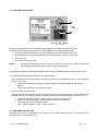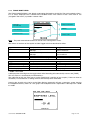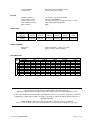
1
PROFESSIONAL PORTABLE
MULTITRACK RECORDER
SONOSAX
SX-R4
USER MANUAL
Soft version 2.5.1746
Audio equipment manufacturer
SONOSAX SAS S.A.
Ch. de la Naz 38
1052 Le Mont s/Lausanne
Switzerland
Tél: +41 21 651 0101
Fax: +41 21 651 0109
Web: www.sonosax.ch / www sonosax.com
Email: [email protected]
Version 1.1 / July 23. 2008
User manual SONOSAX SX-R4
Page 1 of 51
TABLE OF CONTENT
1.
INTRODUCTION ................................................................................................................................................ 4
2.
GENERAL DESCRIPTION................................................................................................................................. 4
2.1
MAIN FEATURES .............................................................................................................................................. 4
2.2
SAFETY INSTRUCTIONS.................................................................................................................................. 5
3.
OPERATING INSTRUCTIONS .......................................................................................................................... 6
3.1
3.1.1
3.1.2
3.1.3
BATTERY POWER ............................................................................................................................................ 6
Opening the battery compartment ........................................................................................................................ 6
Closing the battery compartment .......................................................................................................................... 6
Battery Low alarm................................................................................................................................................. 6
3.2
EXTERNAL DC POWER SUPPLY .................................................................................................................... 6
3.3
SWITCHING ON THE UNIT ............................................................................................................................... 7
3.4
SWITCHING OFF THE UNIT ............................................................................................................................. 7
4.
DETAILED DESCRIPTIONS.............................................................................................................................. 8
4.1
4.1.1
4.1.2
4.1.3
4.1.4
4.1.5
LEFT SIDE PANEL ............................................................................................................................................ 8
Inputs [ IN1 to IN4 ].............................................................................................................................................. 8
Phantom power [ 48V ] ......................................................................................................................................... 8
Pre-LF Cut Filter [ LF Cut ] .................................................................................................................................. 9
Input Attenuator [ PAD ]........................................................................................................................................ 9
Phase reversal [ Ø ] ............................................................................................................................................. 9
4.2
4.2.1
4.2.2
4.2.3
4.2.4
4.2.5
4.2.6
4.2.7
4.2.8
4.2.9
RIGHT SIDE PANEL........................................................................................................................................ 10
Headphone output [ PHONES ] .......................................................................................................................... 10
Stereo/dual-channel Line Input [ STEREO IN ].................................................................................................. 11
Subsidiary Stereo Output [ SUB OUT ].............................................................................................................. 11
External Sync [ SYNC IN ] ................................................................................................................................. 11
Sync Out [ WCKL OUT ].................................................................................................................................... 11
External DC input [ DC IN ]................................................................................................................................ 11
Time Code Connector [ TC ]............................................................................................................................... 12
Digital Input [ ACCESSORY ] ............................................................................................................................. 12
USB2 connector [ USB ] .................................................................................................................................... 12
4.3
FRONT PANEL ................................................................................................................................................ 13
ANALOG SECTION [ IN1 to IN4 ]..................................................................................................................... 13
Input Gain control [ LO-HI ]................................................................................................................................. 13
Channel Linking [ LINK ] ..................................................................................................................................... 13
Led's Peakmeters ............................................................................................................................................... 14
Input Limiter........................................................................................................................................................ 14
Red Led [ OVD LINE] ......................................................................................................................................... 14
4.3.1
4.3.2
4.3.3
4.3.4
4.3.5
5.
5.1.1
5.1.2
5.1.3
5.1.4
5.1.5
5.1.6
5.1.7
5.1.8
5.1.9
5.1.10
5.1.11
5.1.12
USER INTERFACE .......................................................................................................................................... 15
PRINCIPLE OF OPERATION............................................................................................................................. 15
ARCHITECTURE - AUDIO PATH ...................................................................................................................... 16
TRACK MONITORING ....................................................................................................................................... 17
CONTEXTUAL MENUS...................................................................................................................................... 18
SOLO MONITORING ......................................................................................................................................... 19
MONITORING .................................................................................................................................................... 20
LINE OUT ........................................................................................................................................................... 21
SETUP > LINE OUT ......................................................................................................................................... 21
LAST TAKE ........................................................................................................................................................ 22
PLAYER Mode ................................................................................................................................................... 23
Mode SEARCH................................................................................................................................................... 24
UNIT STATUS .................................................................................................................................................... 25
SETUP (Configurations Menus) ......................................................................................................................... 26
User manual SONOSAX SX-R4
Page 2 of 51
5.2
5.2.1
5.2.8
MENU'S TREE STRUCTURE .......................................................................................................................... 27
ROUTING SETTING .......................................................................................................................................... 28
SETUP > ROUTING SETTINGS > ROUTING ................................................................................................. 28
SETUP > ROUTING SETTINGS > MIXING LEVEL ......................................................................................... 28
RECORD SETTINGS ......................................................................................................................................... 29
SETUP > RECORD SETTINGS > PROJECT NAME ....................................................................................... 29
SETUP > RECORD SETTINGS > SCENE NAME ........................................................................................... 29
SETUP > RECORD SETTINGS > FILE FORMAT ........................................................................................... 29
SETUP > RECORD SETTINGS > SAMPLING SETTINGS > SAMPLING FREQUENCY................................ 29
SETUP > RECORD SETTINGS > SAMPLING SETTINGS > SAMPLING UP / DOWN................................... 29
SETUP > RECORD SETTINGS > SAMPLING SETTINGS > SAMPLING RATE............................................. 29
SETUP > RECORD SETTINGS > PRE-RECORD TIME ................................................................................. 30
SETUP > RECORD SETTINGS > PRE-INDEX DELAY................................................................................... 30
SETUP > RECORD SETTINGS > SYNC MODE ............................................................................................. 31
INPUT SOURCE ................................................................................................................................................ 32
SETUP > INPUT SOURCE .............................................................................................................................. 32
TIME CODE........................................................................................................................................................ 32
SETUP > TIMECODE SETTINGS > INPUT SOURCE..................................................................................... 32
SETUP > TIMECODE SETTINGS > INPUT FORMAT..................................................................................... 32
SETUP > TIMECODE SETTINGS > RUNNING MODE ................................................................................... 32
SETUP > TIMECODE SETTINGS > SET MANUAL......................................................................................... 32
SETUP > TIMECODE SETTINGS > SET FROM TIME.................................................................................... 32
MODULOMETERS............................................................................................................................................. 33
SETUP > MODULOMETERS SETTINGS > REFERENCE .............................................................................. 33
SETUP > MODULOMETERS SETTINGS > HOLD TIME ................................................................................ 33
USER SETTINGS............................................................................................................................................... 33
SETUP > USER SETTINGS............................................................................................................................. 33
MISCELANEOUS ............................................................................................................................................... 34
SETUP > MISC > DATE................................................................................................................................... 34
SETUP > MISC > TIME.................................................................................................................................... 34
SETUP > MISC > SYSTEM INFO .................................................................................................................... 34
SETUP > MISC > USER INTERFACE CHECK................................................................................................ 34
SETUP > MISC > FACTORY SETTINGS ........................................................................................................ 34
BROWSE FILES................................................................................................................................................. 35
6.
6.1.1
6.1.2
6.1.3
6.1.4
6.1.5
6.1.6
6.1.7
6.1.8
MANAGING THE SX-R4 ................................................................................................................................. 36
HardDisk and CompactFlash card format........................................................................................................... 36
How to format FAT32 with MAC OSX:............................................................................................................... 36
HD and CF Organisation .................................................................................................................................... 37
USB .................................................................................................................................................................... 38
Alarms ................................................................................................................................................................ 39
Errors treatment.................................................................................................................................................. 40
Software up-date procedure ............................................................................................................................... 41
Recommandations.............................................................................................................................................. 42
7.
APPENDIX ....................................................................................................................................................... 43
Example of a USER SETTING file ......................................................................................................................... 43
X000001.INI (example of file) ............................................................................................................................... 44
partition organization on the HD and the CF Card ............................................................................................ 45
8.
BLOCK DIAGRAM........................................................................................................................................... 48
9.
SPECIFICATIONS ........................................................................................................................................... 49
9.1
SUMMARY OF CHARACTERISTICS .............................................................................................................. 49
5.2.2
5.2.3
5.2.4
5.2.5
5.2.6
5.2.7
User manual SONOSAX SX-R4
Page 3 of 51
1. INTRODUCTION
Congratulations on your purchase of your SONOSAX SX-R4 professional portable audio recorder. Based on
a high techology design, it has been manufactured to deliver many years of excellent performances.
As with all SONOSAX products, the SX-R4 reocrder is built without any compromise in quality, using only
the best components available and a severe quality control. The result of this research and development
project is an ergonomic recorder with extraordinary characteristics and an excellent reliability.
The information and instructions contained in this manual are necessary to ensure safe operations of your
equipment and to maintain it in good working condition; please read it carefully.
2. GENERAL DESCRIPTION
The SONOSAX SX-R4 is a digital audio recorder of the last generation, designed in 2007-2008, using the
latest available technologies, with the unequaled SONOSAX design and ergonomics.
Our 30 years of experience have helped us to develop and build this recorder which is designed to sustain a
long life-span, despite an intensive use under the worst possible conditions. It can be used under the rain
and is resistant to water splashes.
Built in a strong, rugged and anodized aluminum housing, the SONOSAX SX-R4 recorder provides the best
solution whenever top performance, versatility and small size are important. All potentiometers are especially
made for SONOSAX and watertight according to IP45. All capacitors are of professional type, with low loss
and a long life-span
2.1 MAIN FEATURES
♦
8 tracks on HardDisk plus 2 track on CompactFlash Card, with recording capabilities from 44,1 kHz
up to 192kHz at 24 bit and 16 bits ( dithered or troncated )
♦
File format: *.WAV with BWF chunk and iXML metadata
♦
4x Mic/Line transformer-less input with RF Filter, 48V Phantom powering, pre LF-Cut, phase
reversal, PAD attenuator, protection Limiter, Led level metering and extended Linking facilities.
♦
Ultra low noise, high bandwidth,semi-discrete microphone preamplifier.
♦
1x Stereo/two-channel Line input, adjustable from –10dBu to +25dBu
♦
8 x Digital inputs channels ( 4x AES/EBU )
♦
1x Stereo/two-channel Line output, adjustable up to +12dBu
♦
High quality, water resistant, potentiometers and switches ( IP45 )
♦
Full TimeCode capability supporting all frame rates
♦
WordClock I/O and video sync capability, all formats including tri- level & bi-level sync
♦
USB2.0 for high speed file transfert
♦
Low power consumption ( less than 4Watts average ), powered either from 6x standard NiMh AA
cells or external DC power supply from 6 to 18VDC
♦
Small dimensions and light weight, only 0,8kg / 1,75lbs without batteries
User manual SONOSAX SX-R4
Page 4 of 51
2.2 SAFETY INSTRUCTIONS
•
Read all the safety and operation instructions before operating the SX-R4 Recorder and its external
power supply.
•
Keep the instructions for further reference.
•
Follow all warnings, notes and instructions in this operation manual.
•
Keep the SX-R4 Recorder and its external power supply away from heat sources such as radiators
or other devices that produce heat.
•
Connect the SX-R4 Recorder only to the optional external power supply delivered by SONOSAX.
Route power supply cords so that they are not likely to be walked on or pinched by items placed on
or against them, paying particular attention to cords at plugs, inlets and the point where they exit the
console. Keep power cords away from audio cords.
•
Do not drop objects or spill liquids onto the SX-R4 Recorder and its power supply.
•
The SX-R4 Recorder and its external power supply should be serviced only by qualified service
personnel as your nearest SONOSAX authorized reseller.
•
Do not defeat the grounding or polarization of the SX-R4 Recorder mixer or its power supply.
•
Line voltage selectors should only be reseted and equipped with a proper plug for alternate voltage
by a qualified service technician.
•
To reduce the risk of fire or electric shock, do not expose this appliance to rain or moisture.
•
Internal settings must be executed by an authorized SONOSAX distributor or reseller. Damage due
to manipulations inside the unit cancels the SONOSAX warranty immediately.
User manual SONOSAX SX-R4
Page 5 of 51
3. OPERATING INSTRUCTIONS
3.1 BATTERY POWER
The SONOSAX SX-R4 recorder can be internally powered by 6x rechargeable Nickel Cadmium (NiCd) or
Nickel Metal Hydride (NiMH) AA-Cells ( LR6), or disposable Lithium batteries.
WARNING:
Conventional dry cells such as Alkaline batteries should not be used to power the SX-R4 as
they could lead to unexpected powering Off
NOTE:
The running time highly depends on the battery type (NiCd, NiMH or Lithium), the kind of
microphone beeing used and weither the 48V Phantom is turned On. It also depends on the
number of tracks beeing assigned and the sample frequency
3.1.1 Opening the battery compartment
To open the battery compartment located on the rear of the unit, press on both locking pins on each side of
the compartment and slide out the battery holder.
Insert 6x AA-Cells ( LR6 ) and check for correct polarity
WARNING:
Never leave discharged batteries in the compartment. To ensure an optimal running time,
use only premium quality rechargeable cells and check the expiry date
3.1.2 Closing the battery compartment
Slide the battery holder into its compartment. Its shape is designed so it can not be reversed. Press fermly
but without excessive force on both side of the battery holder to securely lock the pins.
3.1.3 Battery Low alarm
When the average voltage per cell reaches 1.05 Volt, an alarm is displayed on the LCD screen and a bip
tone is heard in the headphone. This alarm indicates that the SX-R4 still have a running time of aprox 10 to
20 minutes. When the voltage reaches 1.0 Volt per cell then the SX-R4 will automatically turns Off, thus
protecting your rechargeable batteries from excessive discharge.
NOTE:
If a recording is in progress, the SX-R4 will stop the recording and then properly save the
recorded file on the hard disk before turning Off.
3.2 EXTERNAL DC POWER SUPPLY
SX-R4 Recorder can be powered from any regulated external DC power source from 6 to18 Volts. The DC
source must be capable to sustain at least 1,5A under 12 Volts DC. The average power consumption is
aprox 4 to 7 Watts depending on the microphone powering and the configuration of the SX-R4.
User manual SONOSAX SX-R4
Page 6 of 51
3.3 SWITCHING ON THE UNIT
ON
PLAY
REC
To power On the SX-R4, press simultaneously the Toggle switch and the Joystick to the right
A boot up screen is displayed for approx. 2 seconds and shows the following information:
•
The remaining free available space on the hard disc and on the Compact Flash card
•
A power indication of either the batteries or the external PSU by means of a bar graph
•
Date and Time
•
The currrent firmware version
NOTE:
posting the remaining free space on the HD and on the CF card can take a certain time
depending on effective free space and the number of stored files.
As mentioned the SX-R4 can be powered either from the internal batteries or from an external DC source
.
• Using rechargeable batteries LR6 (AA-cell), NiCd ou NiMH:
Insert 6 batteries in the battery holder and switch On the unit as indicated here above. The LCDscreen
must turn On. If not:
Check that the batteries have been correctly inserted in the battery holder according to the
polarity.
Check that the batteries are properly charged .
• Using an external power source:
Connect the external DC power supply DC plug to the DC IN connector located on the right side of the
recorder and then and switch On the unit as indicated here above. The LCDscreen must turn On. If not:
Check that the external power supply Voltage is between 6 to 18Volts DC
Check that your power supply is strong enough to power on the SX-R4.
Check that the DC plug is correctly wired.
Pin 1 = GND or negative / Pin4 = +VDC or positive
3.4 SWITCHING OFF THE UNIT
Switching OFF the unit is controlled by the software. The fonction [SWITCH OFF] is accessed via the
contextual menu. ( see chapter 5.1.4 )
User manual SONOSAX SX-R4
Page 7 of 51
4. DETAILED DESCRIPTIONS
4.1 LEFT SIDE PANEL
The left side contains the four Mic/Line inputs with their respective function switches as illustrated below:
4.1.1 Inputs [ IN1 to IN4 ]
Each of the input channels is transformer-less, electronically balanced is equiped in standard with a RF Filter
They corresponds to the input channels 1 to 4 of the internal matrixing system.
Input connectors are standard XLR-3 female where:
Pin1 = Gnd / Pin2 = High (+) / Pin3 = Low (-).
To connect an unbalanced source such as CD Player, Minidisk or else, pin 3 must be bridged to pin 1 (Gnd)
and wired to the Gnd on the source. Then use pin 2 for the unbalanced input signal.
WARNING:
Never use the 48V Phantom in case of unbalanced connection or you could severly damage
the sourcing device !
NOTE:
a stereo/dual-channel unbalanced Line input is available in the right side ( see chapter 4.2.1)
4.1.2 Phantom power [ 48V ]
This switch turns the 48V Phantom power On or Off on the corresponfing channel [IN1 à IN4]. In lower
position the 48V phantom is turned On to power condenser microphone. In upper position the Phantom
power is turned Off for connection of Dynamic microphone or any other analog sources.
WARNING:
Never use the 48V Phantom when an external device other than a condenser microphone is
connected to the input or you may severly damage the output circuitries of that device.
Never use the 48V Phantom in case of unbalanced connection
NOTE:
Almost all modern condenser microphones of the latest generation are operating under 48V
Phantom power. Because of the excellent common mode rejection (CMRR) it has been
decided to include only this kind of microphone powering on the SX-R4.
User manual SONOSAX SX-R4
Page 8 of 51
4.1.3 Pre-LF Cut Filter [ LF Cut ]
In lower position, this switch activates a passive low frequency cut circuitry (Pre LF-Cut). The Pre LF-Cut
filter circuitry is acting before the microphone pre-amplifier to attenuates the low frequencies of high level
that could affect the pre-amplifier and thus preventing an optimal setting of the input gain.
These low frequencies of high level can be generated, among other, by the microphone capsule especially
when recording outdoor in strong wind condition.
This Pre LF-Cut frequency is set at 135Hz and its slope is –6dB/octave.
4.1.4 Input Attenuator [ PAD ]
In lower position, this switch activates a 20dB Line attenuator [PAD] on the corresponding channel.
NOTE:
The [PAD] should only be used for high level signals such as Line level coming from an
external device. For an optimanl signal to noise ratio it is recommanded not to use the PAD.
4.1.5 Phase reversal [ Ø ]
In lower position, this switch reverses the phase of the input signal. It can be used to correct a reversed
cable wiring or to address a phase problem between two microphones due to their placement.
User manual SONOSAX SX-R4
Page 9 of 51
4.2 RIGHT SIDE PANEL
This panel contains followings connections:
•
Headphone output [PHONES] on a ¼" jack
•
Unbalanced stereo/dual-channel Line input [STEREO IN] with adjustable sensivity
•
Unbalanced stereo/dual-channel Line output [SUB OUT] with adjustable output level
•
External Video or Wordclock sync input [SYNC IN] and Wordclock output [WCKOUT]
•
Digital Input AES 1 to AES 4 on a 26 pin multiway connector
•
TimeCode input/output [TC] all format on a 5 pin Lemo
•
External 6 to 18 Volts DC power supply [DC IN] on a 4 pin Hirose
•
USB2 high seed connector [USB] for connection to any computer
•
CompactFlash card slot
NOTE:
The mating cable connector for the [STEREO IN] and the [SUB-OUT] a TA-3 female.
It is available under SONOSAX part nr SX860266 or Swtichcraft TA3FX
4.2.1 Headphone output [ PHONES ]
The headphone output on a 6,25mm ( ¼" ) jack allow connection of any mono or stereo headphone having
an impedance greater than 30 ohms.
The headphone level is adjustable by the Joystick ( see chapter 5.1.3 ). Pressing the Joystick to the left will
decrease the volume, pressing the Joystick to the right will increase the volume. The volume control is only
possible while in REC Mode or in PLAY mode.
The combination of tracks to be monitored and the monitoring mode is set in the [MONITORING] menu. It is
also possible to listen to each track individualy (mode SOLO , chapter 5.1.5)
The headphone connector [PHONE] is a stereo jack 6,35mm ( 1/4" ) where:
Sleeve = Gnd / Ring = Right / Tip = Left
WARNING:
the headphone amplifier of the SX-R4 is quite poweful. It is recommanded to set the
headphone level for a reasonable loudness to protect your precious ears
User manual SONOSAX SX-R4
Page 10 of 51
4.2.2 Stereo/dual-channel Line Input [ STEREO IN ]
This unbalanced stereo/dual-channel Line Input is provided to connect any external device to the SX-R4
such as for example a SONOSAX SX-M32 or SX42 mixer, receivers of wireless systems or any other
external analog source.
The input signal corresponds to the Input channels 5 (Left) & 6 (Right) in the routing matrix system.
The retractable potentiometer adjusts the input sensivity from
–10dBu to +25dBu to reach a digital
recording level of 0dBFS
The [STEREO IN] connector is a mini-XLR TA-3 male where:
Pin1 = Gnd, Pin2 = Left channel, Pin3 = Right channel.
4.2.3 Subsidiary Stereo Output [ SUB OUT ]
This unbalanced stereo/dual-channel Line Output is provided to send a rough pre-mix to any external analog
device such as for example a video camera, a transmitter or an alternative monitoring system.
This stereo/dual-channel [SUB OUT] is totally independent of the [PHONES] output and has its own
matrixing/mixing system. The combination of tracks and their routing to the Left or Right channel is similar to
the Monitoring system but is defined in the [LINE OUT] menu. It offers the same facilities including the Mono
summing and the M/S decoding ( see chapter 5.2.4 )
For ease of connections, this Line output is provided simultaneously on a TA-3 connecotr and a stereo MiniJack wired in parallel. The mini-jack can also accommodate a headphone. (minimum impedance is 30ohms )
The retractable potentiometer adjusts the output Level between from –10dBu to +25dBu for 0dBFS.
The [SUB OUT] connector is a mini-XLR TA-3 male where:
Pin1 = Gnd, Pin2 = Left channel, Pin3 = Right channel.
4.2.4 External Sync [ SYNC IN ]
This SMA connector provides an input for an external Wordclock or a Video reference. Thus, it allows to
synchronize the A/D Converters of the analog inputs 1 to 6 on an external reference. The selection of the
synchronisation signal is achieved in the contexctual menu ( see chapter 5.2.2 )
4.2.5 Sync Out [ WCKL OUT ]
This SMA connector delivers a Wordclock sync signal. Its frequency depends either of the selected sample
frequency selected in the in the "Sampling settings" menu, or of the incoming frequency of the [SYNC IN] if it
is a valid WordClock, or of the sample frequency of the incoming AES input if a valid AES input in connected
on chanel 7/8 and properly routed in the matrix system.
4.2.6 External DC input [ DC IN ]
The SONOSAX SX-R4 can be powered by means of an external DC supply, either a main adapter or an
external high capacity battery bank. The voltage must be regulated between 6 to 18VDC
The average power consumption of the recorder is around 4 Watts. This represents a DC current of 330mA
under a supply voltage of 12Volts. However, while turning On the recorder the inrush current mayreach 2A,
therefore make sure that your external DC supply can sustain this peak of current
To ensure optimal performances we recommand you to use the optional main adapter available by your
local dealer.
the DC IN connector is a Hirose 4 pin female :
Pin 1 = Gnd ou negative / Pin4 = +V DC or positive; the voltage range is 6 to 18 Volts DC
The Hirose 4 pin male cable connector is available by SONOSAX or by your local dealer under references:
SONOSAX part nr SX860217 or Hirose HR10-7P-4P
User manual SONOSAX SX-R4
Page 11 of 51
4.2.7 Time Code Connector [ TC ]
The TimeCode input/output connector is a Lemo 5 pin, compatible with the Aaton wiring as below:
Pin 1 = Gnd
Pin 2 = Smpte Out
Pin 3 = not connected
Pin 4 = not connected
Pin 5 = Smpte In
The mating cable connector Lemo 5 pin is available by SONOSAX or by your local dealer under ref part
SONOSAX SX-860232 or Lemo FGG.0B.305.CLAD52
4.2.8 Digital Input [ ACCESSORY ]
This 26pin connector provides 4x AES/EBU digital audio inputs [AES1 to AES4]. The sync signals such as
the Sync In and the Wckl Out, the Time Code In and Out and the Monitor Out are internaly wired in paralel to
the corresponding main connectors. The serial bus is provided for future use
The mating cable connector is available under SONOSAX ref: SX-860570
Split cables wired for the 4x AES inputs are also available, please check with your local dealer.
4.2.9 USB2 connector [ USB ]
This connector is of USB2 type only. The SX-R4 is not compatible with anciliary USB 1.0 system
It allows to connect the SX-R4 to any computer ( PC or Mac ) providing with aa standard USB2 port. As soon
as connected, the SX-R4 will appear on the computer desktop as an external Harddisk drive. If a Compact
Flash card is inserted, it will also appears on the desktop.
WARNING:
It is highly recommanded to use a Certified "USB 2 High Speed" cable. The data rate
transmission is so high that using a non certified cable may lead to unpredictable malfunctions
such as : Disk not recognized, SX-R4 nor appearing on your desktop, Windows error code 10
etc etc
User manual SONOSAX SX-R4
Page 12 of 51
4.3 FRONT PANEL
The front side of the SX-R4 contains all functions commonly used during a recording session. It has two
distinct sections: the analog section that controls the inputs channels and the User Interface that controls all
functions of the recorder
ANALOG SECTION [ IN1 to IN4 ]
This section covers the functions related to input control such as Gain level, channels linking. It also offers a
small 3 led peak-meters to visualize the modulation level, the eventual overloads and also to indicates the
Limiter activities.
4.3.1 Input Gain control [ LO-HI ]
The input gain is controlled jointly by the gain switches [ LO-HI ] and the gain potentiometer.
position High [ HI ] the input sensivity goes from –18,5dBu to –61,0dBu for 0dBFS
position Low [ LO ] the input sensivity goes from +1.5dBu to –38.5dBu for 0dBFS
position Low [ LO ] with [ PAD ] the input sensivity goes from +21.5dBu to –18.5dBu for 0dBFS
NOTE:
Gain control should be used with care since the adjustment range is extensive. A signal level
set too high can cause distortion and will leave you with less headroom; a level set too low
causes a bad signal-to-noise ratio.
4.3.2 Channel Linking [ LINK ]
This switches allow to Link the Gain potentiometers of the input channels, thus a single potentiometer
controls two or more channels which ensure to keep the stereo balance of a stereo microphone, a M/S pair
or any other stereo source.
The Linking can be done either per pairs of channels such as for example 1&2 and/or 3&4, or for 3 channels
such as for double M/S system by linking channels 2 & 3 & 4, or even all 4 channels together as for the
Soundfied "B-Format" where all four channels will be linked to channel # 4 that has a quad potentiometer.
The Linkings are achieved as follow:
Channel nr 1:
lower position = no linking
position 2 = Link channel 1 to channel 2. Fader nr 2 controls channels 1 & 2
position 4 = Link channel 1 to channel 4. Fader nr 4 controls channels 1 & 4
Channel nr 2:
lower position = no linking
position 3 = Link channel 2 to channel 3. Fader nr 3 controls channels 2 & 3
position 4 = Link channel 2 to channel 4. Fader nr 4 controls channels 2 & 4
Channel nr 3:
lower position = no linking
position 4 = Link channel 3 to channel 4. Fader nr 4 controls channels 3 & 4
User manual SONOSAX SX-R4
Page 13 of 51
4.3.3 Led's Peakmeters
This small peak meters has three distinct functions. It indicates not only the input level of the channel but
also the Limiter activities as soon as the signal reaches the threshold level and the eventual overloads.
These meters are connected at the input of the A/D Converter
Level indication:
Green Led:
Yellow Led:
Red Led:
the modulation reaches an internal level of aprox -20dB.
the modulation reaches the nominal internal level 0dB (-18dBFS)
the modulation reaches an internal level of aprox +10dB
Limiteurs:
The Limiteur activity is shown by lighting simultaneously the Red and the Green led's for
a period of aprox 1 second
Overloads:
the overload is indicated as soon as the clipping level is reached 0dBFS. In this case all
led's light at the same time
NOTE:
The Leds intensity vary automatically depending on ambiant light. It is controlled by the light
sensor located on the left side of the Joystick
4.3.4 Input Limiter
Each of the 4 input channel is equiped with a protection Limiter which is part of the microphone pre-amplifier
design. The Limiter is automatically activated 2dB below the clipping level of the A/D converter (–2dBFS)
and can not be de-activated. The Threshold is set at factory and can not be modified by the user
The Limiter activities is indicated by the 3 Leds Peak-Meter by lighting the Red and the Green Led for a
period of aprox 1 second.
4.3.5 Red Led [ OVD LINE]
This Red Led indicates the eventual overload on the Line Inputs 5 & 6. It lights as soon as the clipping level
of the A/D Converter 5&6 is reached
User manual SONOSAX SX-R4
Page 14 of 51
5. USER INTERFACE
Light
LCD Screen
10 lines x 17 characters
Joystick
Green LED
Red LED
Toggle Switch
PLAY
REC
5.1.1 PRINCIPLE OF OPERATION
Status
The Status of the SX-R4 is displayed by means of the Red and the Green leds and by the LCD Display. The
following status are possible:
•
RECORD READY
the Red LED is flashing, the SX-R4 is ready to start recording.
•
RECORDING
the Red LED lights On steady, confirming that a recording is in progress
•
PLAYING
the Green LED lights On steady, a Take is playing
•
PLAY PAUSE
the Green LED flashes, indicating that the loaded Take is currently paused.
•
PLAY STOP
A Take is loaded ready to be played, no LED lights on, nor flashes
Main scren display
The main working screen [ TRACK MONITORNG ] displays the Level Meters of the 8 tracks.
The global meter's range is 72dB with following resolutions :
1dB steps from –72dBFS up to –24dBFS
0.5dB steps from –23.5dBFS up to 0dBFS.
A configurable reference line can be displayed at -9, -12, -18, or –20 dBFS (see configuration menu)
Convention for displayed informations and function keys
The last line on the screen displays the Joystick's function.
By default, pushing the Joystick Up or Down modifys the parameters, to the Right will select the parameter
and to the Left cancel the action or steps back in the contextual menu.
A single Arrow symbol denotes that an action is achieved by briefly pushing the Joystick.
A double Arrow symbol means that the Joystick must be pushed longer to achieve the action.
A round Dot symbol denotes a pressure on the center of the Joystick
User manual SONOSAX SX-R4
Page 15 of 51
5.1.2 ARCHITECTURE - AUDIO PATH
The SONOSAX SX-R4 offers 14 physical input channels, 6 analog and 8 digital. Up to 8 of these physical
input channels can be assigned to any of the 10 available tracks, and any analog/digital channel
combination is possible. These physical channels are groupped per pair as follow:
•
•
•
•
1, 2 : either MIC/LINE input 1 & 2 or AES 1
3, 4 : either MIC/LINE input 3 & 4 or AES 2
5, 6 : either LINE input 5 & 6 or AES 3
7, 8 : AES4 only
The routing Matrix allows to asssign and mix any of the input channels to any of the 10 available tracks.
The first 8 tracks are dedicated to the hard disc (HD) and the 2 additional tracks are dedicated to the
Compact Flash card (CF).
For Monitoring purposes, you can configure and listen to any combination of these 10 tracks. However, the
display shows only the Peak meters of the 8 hard disk's tracks
Channel 1
Channel 2
Mixer coeficients
Channel 3
Channel 4
Mixer
Channel 5
Channel 6
Channel 7
Channel 8
1
2
3
4
Tracks
5 6 7
8
9 10
Modulometers values
Left
Right
Modulometers
Monitor
Monitor config
Left
Right
Line out
Line out config
Bits per sample
Wave encoder
FAT32 / ATA layer
HDD
User manual SONOSAX SX-R4
CF
Page 16 of 51
5.1.3 TRACK MONITORING
The TRACK MONITORING is the default page beeing displayed by the SX-R4. The track numbering from 1
to 8 is always displayed and is related to the HardDisk tracks. The number of each active track in use
(assigned in the matrix ) is posted in reverse video.
Battery level indicator
Timecode
(HH :MM :SS)
TAKE Nr
Track Metering
Reference Level
Function of the
Note: The peak meter reference level can be set in the "Configuration" menu.
The actions or functions of the Joystick and the Toggle switch are described as follow:
Joystick
LEFT
Long pressure
Reduce the volume continuously
down to minimum
Increase the volume continuously
up to maximum
UP and DOWN
CENTER
Short pressure
Reduce the headphone volume in
1dB steps
Increase the headphone volume in
1dB steps
SOLO MONITORING
Call the contextual Menu page
Toggle switch
RIGHT
RIGHT while recording
LEFT
LEFT while playing
Short pressure
Start recording
Add an Index **
Call and Play the last take
Pauses at current position
Long pressure
RIGHT
Lock/Unlock the Joystick action
Stop recording
Stop playing
** Index = New TAKE
A brief pressure to the Right on the toggle switch while Recording will automatically create a new [TAKE].
This new Take nr is automatically incremented by 1.
The audio files of this new Take are cut at the sample level ( precision of one sample ). Takes can then be
seamlessly re-assembled in an editing software with the help of the TimeCode.
Pressing the Joystick to the Left or to the Right displays temporarily will post a temporary screen showing
the headphone level by means of a bar graph. The headphone level is adjustable in 1dB steps from –30dB
to +18dB.
User manual SONOSAX SX-R4
Page 17 of 51
5.1.4 CONTEXTUAL MENUS
The Contextual Menu allows a quick navigation between the different pages and configurations menu of the
SX-R4. The Contextual Menu can only be accessed from the Track Monitoring page ( not while in Solo
Monitoring Mode ) by a pressure on the center of the Joystick.
Joystick
LEFT
RIGHT and CENTER
UP
DOWN
Short pressure
Long pressure
Steps back from the menu to the
Tracks Monitoring page
Confirm the selection
Scroll the selection upward
Scroll the selection downward
The possible choices in the Contextual Menu depend on the current "Status" of the SX-R4 as described here
below:
While Recording:
• >Monitoring
• >Line Out
• >Unit Status
While Playing or in Pause:
• >Last Takes
• >Monitoring
• >Line Out
• >Unit Status
• >Delete Take
While in Record Ready:
• >Monitoring
• >Line Out
• >Last Takes
• >Unit Status
• >Setup
• >Browse Files
• >Switch Off
While in Stop:
• >Last Takes
• >Exit Player Mode
• >Monitoring
• >Line Out
• >Unit Status
• >Browse Files
• >Delete Take
• >Switch Off
User manual SONOSAX SX-R4
Page 18 of 51
5.1.5 SOLO MONITORING
The [SOLO MONITORING] page is accessed from the [TRACK MONITORING] page by pressing the
Joystick Up or Down. It allows you to Monitor in mono any individual track or a specific pair of tracks.
The page beeing displayed is visually almost identical to the [TRACK MONITORING] page with the
expection that a round dot indicates the selected track being soloed.
The track selection sequence is as follow: 1, 2, 1+2, 3, 4, 3+4, 5, 6, 5+6, 7, 8, 7+8.
The UP key moves the selection upward; the DOWN key moves the selection downward
The Solo Monitoring is only possible with active (assigned) tracks
Joystick
LEFT
RIGHT
UP
DOWN
CENTER
Short pressure
Reduce the headphone volume in
1dB steps
Increase the headphone volume in
1dB steps
Select the previous track
Select the next track
Returns to the
TRACKS MONITORING
Long pressure
Reduce the headphone
volume continously
Increase the headphone
volume continously
Lock/Unlock the Joystick
The example above shows a configuration of 4 active (or assigned ) tracks: 1, 2, 3, and 5.
Track 1 being currently selected for Solo Monitoring.
In this particular case, the selection sequence for the Solo is: 1, 2, 1+2, 3, 5
User manual SONOSAX SX-R4
Page 19 of 51
5.1.6 MONITORING
This Monitoring page is used to configure and mix the 10 tracks of the SX-R4 for it's headphone output.
The configuration of the monitoring is done by means of a specific menu as shown below :
The Monitoring is always configured per pair of tracks ( 10 tracks = 5 pairs of tracks )
The table below shows the available choices and their respective monitoring results on the stereo
headphone output for the pair of tracks 1 and 2.
Monitoring Mode
--MONO
STEREO
REV STEREO
MS
MONO L
MONO R
Result on the Left channel
--1+2
1
2
1+2
1+2
---
Result on the Right channel
--1+2
2
1
1–2
--1+2
The table below descibes the actions of the Joystick :
Joystick
LEFT
RIGHT
UP
DOWN
CENTER
Short pressure
Change the monitoring mode.
Change the monitoring mode.
Move the selector upward
Move the selector downward
Save the modifications and
return to the previous Menu
Long pressure
Note: If a pair of tracks is not activated (not assigned) the only possible value is : " --- " (No Monitoring)
User manual SONOSAX SX-R4
Page 20 of 51
5.1.7 LINE OUT
SETUP > LINE OUT
The SX-R4 provides with a stereo/two-channels line output [SUB OUT] that can be used to record a sub-mix
onto a camera, or to send it via a wireless link or simply to provide with an alternate monitoring selection.
This line output can be configured on the same maner as the Monitor. Thus, this menu allows to assign and
mix the 10 tracks to the [SUB OUT] connectors as described here below:
The Line Out is always configured per pair of tracks (10 tracks = 5 pairs of tracks). The table below shows
the available choices and their respective results on the [SUB OUT] output for the pair of tracks 1 and 2.
Type
--MONO
STEREO
REV STEREO
MS
MONO L
MONO R
Result on the Left channel
--1+2
1
2
1+2
1+2
---
Result on the Right channel
--1+2
2
1
1–2
--1+2
The table below shows the actions of the Joystick :
Joystick
LEFT
RIGHT
UP
DOWN
CENTER
Short pressure
Change the Line Out mode.
Change the Line Out mode.
Move the selector upward
Move the selector downward
Save the modifications and
return to the previous Menu
Long pressure
Note: If a pair of tracks is not activated (not assigned) the only possible value is: " --- " (no output)
User manual SONOSAX SX-R4
Page 21 of 51
5.1.8 LAST TAKE
This page provides a quick access to the Last Takes having been recorded. The Takes appear in a reverse
order, thus the last Take appears at the top of the list.
The first line displays the date (YY/MM/DD) and the start time of the selected Take
Each TAKE is presented with following format:
XX YYYYYYYY-ZZZ
Where:
XX is the media source where the TAKE is stored (HD or CF)
YYYYYYYY is the scene name (max 8 characters)
ZZZ is the TAKE number
By selecting a TAKE, the SX-R4 loads it to it's memory. Depending of the media source and the TAKE
length, it may take a certain time before the TAKE becomes ready for the Playback.
Joystick
LEFT
RIGHT or CENTER
UP
DOWN
User manual SONOSAX SX-R4
Short pressure
Return to the CONTEXTUAL MENU
Load the selected TAKE
Scroll the selector upward
Scroll the selector downward
Long pressure
Page 22 of 51
5.1.9 PLAYER Mode
This page is posted when a TAKE is selected
Joystick
LEFT
RIGHT
UP and DOWN
CENTER
Toggle switch
LEFT
LEFT while Playing
RIGHT
RIGHT while Recording
** NOTE:
Short pressure
Reduce the headphone volume in
1dB steps
Increase the headphone volume in
1dB steps
Activate the SOLO MONITORING
Return to CONTEXTUAL MENU
Long pressure
Reduce the headphone volume
continously
Increase the headphone volume
continously
Short pressure
Play the selected Take
Pauses at current position
Switches to Record mode and start
recording (scratch record**)
Add an Index
Long pressure
Lock/Unlock
Stop playing
Stop recording
while switching directly from Play mode to Record mode by pressing the Toggle switch to the
Right, the SX-R4 starts recording immediately (scratch record). In this case the pre-record
buffer remain empty, thus the pre-record time is equal to zero.
User manual SONOSAX SX-R4
Page 23 of 51
5.1.10 Mode SEARCH
The SEARCH mode can only be activated while the Player is in => PAUSE mode ( not from Stop mode)
Pressing the Joystick to the Left or to the Right respectively Fast Rewinds or Fast Forwards within the
selected TAKE.
in SEARCH mode => FORWARD
One pressure to the Right:
>>
Fast Forwards at 2x the Play speed with Monitoring
2 quick pressure to the Right:
>>>
Fast Forward in steps of 5% of the TAKE length,
no monitoring
<<<
Fast Forward in steps of 5% of the TAKE length,
no monitoring
in SEARCH mode => REWIND
One pressure to the Left:
in SEARCH mode => PAUSE
No action on the Joystick
Joystick
LEFT
1 pressure
<<< Fast Rewing, no monitoring
2 quick pressures
RIGHT
>> Fast Forward with monitorng
(2x Play speed)
>>> Fast Forward, no monitoring
UP and DOWN
CENTER
Activates the SOLO MONITORING
Return to CONTEXTUAL MENU
Toggle switch
LEFT while in Pause
LEFT while Playing
Short pressure
Play from current position
Pauses at current position
Fast Rewind " <<< "
User manual SONOSAX SX-R4
Long pressure
Change from Pause to Stop
Stop playing
Fast Forward " >>> "
Page 24 of 51
5.1.11 UNIT STATUS
This page displays the main current parameters of the SX-R4
.
Battery Level Indicator
Project Name
Loaded User Setting
Scene Name
Take Number
Sampling informations
HD & CF remaining free
space
Timecode
The displayed parameters are:
•
Line 1 :
the battery level indicator or a dart symbol if an external PSU is connected
•
Line 3 :
the current Project name,
the loaded User Setting (posted only if the loaded setting has not been modified)
•
Line 4 :
Scene name and Take number
•
Line 5 :
Sampling rate (24/16) / Sampling frequency, synchronisation source such as
INTERNAL, AES, WCK IN
or video stream type: PAL/25, NTSC/29.97, 1080/23.97, 1080/24, 1080/25, 1080/29.97,
1080/30, 720p/24, 720p/25, 720p/29.97, 720p/30, 720p/50, 720p/59.94, 720p/60,
295M-P/25 or Video Err.
•
Line 6 :
Timecode and its format: Int (Internal), 24, 25, 29 (29.97 Non Drop),
29D (29.97 Drop), 30 (30 Non Drop) or 30D (30 Drop). If the Time Code cannot be read
(unknown format) the Time Code value becomes: -- :-- :--
•
Line 7 :
Remaining free space on the Hard Disc
•
Line 8 :
Remaining free space on the CompactFlash card
Joystick
LEFT
User manual SONOSAX SX-R4
Short pressure
Return to CONTEXTUAL MENU
Long pressure
Page 25 of 51
5.1.12 SETUP (Configurations Menus)
The Configuration Menus are posted by calling the Contextual Menu and then by selecting [SETUP] in the
list. The menus are sorted in headings (rubrics), and grouped in a logical order. The navigation from heading
to heading is done by pushing the Joystick UP or DOWN. On the right side of the screen, a scroll bar
indicates the position in the list of the available headings.
Press the Joystick to the RIGHT or CENTER to enter the sub-menu, to the LEFT [EXIT] or [BACK] to return
to the preceeding page.
The tree structure of the menus imposes the use of sub-menus until the parameter which one wishes to
modify is reached.
A menu with no parameter shown, posts one heading per screen. Thus
classifying the various selectable parameters.
A menu showing parameters corresponds to the end of the tree
structure; thus it posts the current value of the parameter that can be
modified.
Pressing the Joystick to the RIGHT or CENTER, in a menu with
parameter, allows to change its value. One distinguishes several
manners of carrying out this change
.
A menu with a list shows the possible choices of a parameters. The
selection is posted in reverse video
The text-editing menu.
The text to be edited is displayed between brackets which shows the
limits of the text size.
Two arrows point the selected character. Press the Joystick Up or
Down to modify the selected character. Keep pressing to scroll the
characters. LEFT and RIGHT moves the cursor to select the character.
Pressing the Joystick on its CENTER save the text and return to the
preceeding page.
A long pressure to the LEFT cancels the edition and returns to the
preceeding page.
User manual SONOSAX SX-R4
Page 26 of 51
5.2 MENU'S TREE STRUCTURE
The grayed menus are those where parameters are visible.
Level 1
Level 2
Level 3
ROUTING
SETTINGS
ROUTING
Specific Menu (cross matrix)
RECORD
SETTINGS
MIXING LEVEL
NONE, ATT1.5, ATT3, ATT6
PROJECT NAME
SCENE NAME
FILE FORMAT
Text Editor
Text Editor
MONO, STEREO
44.1, 48, 88.2, 96, 176.4, 192 kHz
Nominal, UP o/oo, DOWN o/oo
24 bits, 16 bits dither, 16 bits
SAMPLING
SETTINGS
SAMPLING FREQUENCY
SAMPLING UP/DOWN
SAMPLING RATE
PRE-RECORD
TIME
PRE-INDEX
DELAY
SYNC MODE
INPUT
SOURCE
1, 2, 5, 10, 20 sec
0, 1, 2, 3, 5 sec
OFF, WDCKIN, VIDEO IN
MIC/LINE 1-2
MIC/LINE 3-4
LINE 5-6
AES, MIC/LINE
AES, MIC/LINE
AES, LINE
EXTERNAL JAM SYNC,
EXTERNAL NO JAM,
INTERNAL,
INTERNAL OUTPUT
AUTODETECT, 24, 25,
29.97 NON-DROP, 29.97 DROP,
30 NON-DROP, 30 DROP
SOURCE
TIMECODE
SETTINGS
Changeable values
FORMAT
RUNNING MODE
FREE RUN, RECORD RUN
SET MANUAL
MODULOMETERS
SETTINGS
USER
SETTINGS
SET FROM TIME
REFERENCE
HOLD TIME
Specific menu
DATE
TIME
SYSTEM INFO
MISC
NONE, -9, -12, 18, -20 dB
NONE, 5 sec, 10 sec, 2 min,
INFINITE
USER
INTERFACE
CHECK
FACTORY
SETTINGS
Specific Menu to set up Date
Specific Menu to set up Time
Post the software/hardware
revisions and battery voltage
Check the LCD display, the LEDs
and the functions of the keys
Re-set all parameters to factory
default
Explanation of each menu is detailled in the following chapters.
User manual SONOSAX SX-R4
Page 27 of 51
5.2.1 ROUTING SETTING
SETUP > ROUTING SETTINGS > ROUTING
The routing, or channel assignement to the tracks, is done by means of a specific menu as shown below:
Tracks
Routing Matrix
Input
Channels
The round dot assigns the Inputs Channels to the Tracks. Any combination is possible and any input
channel can be routed to any track. An input channel can be routed to multiple tacks and multiple channels
can be routed on the same track ( mixing ). In the figure above, a 1x1 routing is established between the
Inputs and the Hard Disc Tracks. In addition, input channels 1 & 2 are also routed to the CF card
The table below shows the actions of the Joystick :
Joystick
LEFT
RIGHT
UP
DOWN
Short pressure
Long pressure
Move the selection cursor to the Left
Return to the previous menu
Move the selection cursor to the Right
Move the selection cursor upward
Move the selection cursor downward
CENTER
Activate/Desactivate the assignement
NOTES:
It is not possible to leave this menu without saving the configuration
The un-assigned Tracks (no dot on the crossing) are automatically desactivated.
SETUP > ROUTING SETTINGS > MIXING LEVEL
The [MIXING LEVEL] menu defines the attenuation to be applied to each channel when summing (mixing)
multiple input channels onto the same track, thus avoiding a possible digital clipping. Four possibilities are
offered and the choice depends on the phase coincidence of the sources.
•
•
•
•
NONE
ATT1.5
ATT3
ATT6
no attenuation at all
mainly used if the sources have no phase coincidence
recommanded for phase coincident sources such as sereo or M/S microphone
only used if the sources are absolutaly in phase
The table below summarizes the exact attenuations computed and applied according to the number of input
channels assigned to the same track.
Number of input channels
assigned to the same track
1
2
3
4
5
6
7
8
User manual SONOSAX SX-R4
NONE
[ in dB ]
0
0
0
0
0
0
0
0
ATT1.5
[ in dB ]
0
1.8
2.5
3.3
3.3
4.1
4.1
5
ATT3
[in dB ]
0
3.3
5
6
7.2
7.2
8.5
8.5
ATT6
[ in dB ]
0
6
10.1
12
14.5
14.5
18.1
18.1
Page 28 of 51
5.2.2 RECORD SETTINGS
SETUP > RECORD SETTINGS > PROJECT NAME
This menu allows you to set the PROJECT Name. It has several aims:
•
•
Sets the name of the directory where the Takes will be stored.
Archives the Project name in each WAVE file (sub-chunk BWF and iXML)
The format of the Project Name is as follows:
•
•
8 characters maximum
alphanumeric characters, space and underscore only (A..Z, 0..9, _)
SETUP > RECORD SETTINGS > SCENE NAME
This menu allows you to set the SCENE Name. It has also several aims:
•
•
Partially names the directory where the audio files of the Takes will be stored
Archives the Scene name in each WAVE file (sub-chunk BWF and iXML)
The format of the Project Name is as follows:
• 8 characters maximum
• alphanumeric characters, space and underscore only (A..Z, 0..9, _)
SETUP > RECORD SETTINGS > FILE FORMAT
The File format offers two choices :
•
•
MONO
STEREO
If MONO is selected, each track is recorded in a separate mono file.
If STEREO is selected, the system records each pair of tracks in a stereo file. The pairs are always 1+2,
3+4, 5+6 and 7+8.
If the Routing defines incomplete pairs of tracks (for example tracks 1, 3, 4 and 7) each insulated track is
recorded in a stereo file and uses a half of the file size.
SETUP > RECORD SETTINGS > SAMPLING SETTINGS > SAMPLING FREQUENCY
This menu lets choose the sampling frequency. Choices are : 44.1, 48, 88.2, 96, 176.4 and 192 kHz.
If a AES input is assigned, then the SX-R4 will automatically lock on the incoming AES sample frequency
and thus the selected sampling frequency will be overwritten.
WARNING:
The DSP of the SX-R4 will lock on the incoming sample frequency, however both the BWF
and iXML header will stamp the sample frequency that was selected in this menu.
SETUP > RECORD SETTINGS > SAMPLING SETTINGS > SAMPLING UP / DOWN
The Pull-Up / Pull-Down correction for the NTSC world can be set in this MENU. The possible values are
NOMINAL (use of the nominal sampling value), UP ‰ (positive correction of one per thousand) and DOWN
‰ (negative correction of one per thousand).
SETUP > RECORD SETTINGS > SAMPLING SETTINGS > SAMPLING RATE
This menu sets the number of bits per sample (also called sampling rate or bit depth) recorded in the WAVE
files. The possible values are 24 bits, 16 bits dither and 16 bits. The dithering is of the triangular type.
User manual SONOSAX SX-R4
Page 29 of 51
SETUP > RECORD SETTINGS > PRE-RECORD TIME
The Pre-Record time can be set from 1 second up to 20 seconds. The selected value may not always be
possible due to the physical limitation of the built-in memory and the selected configuration.
The Pre-Record time depends on following factors:
•
•
•
Number of Tracks being assigned
Sampling frequency
Sample Rate and Pull UP/ Pull DOWN correction
When the required pre-record time is not possible, the SX-R4 will perform on "best effort" basis to provide
with the maximum possible. The table below shows the max. values of the pre-record time [sec.]:
16 bits
fs
44100
48000
88200
96000
176400
192000
1
20.0
20.0
20.0
20.0
20.0
20.0
2
20.0
20.0
20.0
20.0
20.0
19.1
3
20.0
20.0
20.0
20.0
13.9
12.7
4
20.0
20.0
20.0
19.1
10.4
9.6
Tracks count
5
6
20.0 20.0
20.0 20.0
16.6 13.9
15.3 12.7
8.3
6.9
7.6
6.4
7
20.0
20.0
11.9
10.9
5.9
5.5
8
20.0
19.1
10.4
9.6
5.2
4.8
9
18.5
17.0
9.2
8.5
4.6
4.2
10
16.6
15.3
8.3
7.6
4.2
3.8
24 bits
fs
44100
48000
88200
96000
176400
192000
1
20.0
20.0
20.0
20.0
20.0
20.0
2
20.0
20.0
20.0
20.0
13.9
12.7
3
20.0
20.0
18.5
17.0
9.2
8.5
4
20.0
20.0
13.9
12.7
6.9
6.4
Tracks count
5
6
20.0 18.5
20.0 17.0
11.1 9.2
10.2 8.5
5.5
4.6
5.1
4.2
7
15.9
14.6
7.9
7.3
4.0
3.6
8
13.9
12.7
6.9
6.4
3.5
3.2
9
12.3
11.3
6.2
5.7
3.1
2.8
10
11.1
10.2
5.5
5.1
2.8
2.5
In these tables, the UP/DOWN correction is not taken into account (negligible).
SETUP > RECORD SETTINGS > PRE-INDEX DELAY
The pre-index delay reflects the time of anticipation, to compensate the user reaction time, when adding an
index. It offers the following values: 0, 1, 2, 4 and 5 seconds. The graph below illustrates an example of this
Pre-Index delay
TAKE 27
TAKE 28
Adding an Index ( by pressing the toggle switch to REC )
PRE-INDEX DELAY
t
The pre-delay index is not absolute; the software does its best to cut the Take to nearest desired time (best
effort). However, no data is lost during the addition of an index !
User manual SONOSAX SX-R4
Page 30 of 51
SETUP > RECORD SETTINGS > SYNC MODE
The synchronization mode of the SX-R4 can be choosen in this menu. By synchronization, one means the
use of an external clock on a given signal to synchronize the selected sample frequency of the SX-R4.
This section does not treat the use of timecode.
The current active mode of synchronization is posted in the page "Unit Status".
All modes are explained below with the various parameters and their validity
OFF
Internal Generator:
The SX-R4 has a very stable internal clock generator, capable of generating all the sample frequencies
(44.1, 48, 88.2, 96, 176.4 and 192 Khz).
This generator is used only when no other clock is available.
•
•
•
Sampling frequency:
Sampling up/down:
Sampling rate:
active
active
active
Synchronisation on AES input:
The SX-R4 is automatically locked on the incoming AES clock of the channels 7-8
•
•
•
Sampling frequency:
Sampling up/down:
Sampling rate:
inactive
inactive
active
WCK IN
Synchronisation WCK IN
WCK IN must be set in the menu SYNC MODE to use the Word Clock connected on the [SYNC IN]. This
mode is not used if a valid AES signal is present.
•
•
•
Sampling frequency :
Sampling up/down :
Sampling rate:
inactive
inactive
active
VIDEO IN
Synchronisation Video IN
VIDEO IN must be set in the menu SYNC MODE to use the Clock of a Video feed
This mode is not used if a valid AES signal is present.
• Sampling frequency : active
• Sampling up/down :
inactive
• Sampling rate:
active
User manual SONOSAX SX-R4
Page 31 of 51
5.2.3 INPUT SOURCE
SETUP > INPUT SOURCE
This menu is used to choose and select which input source will be applied to the channels 1-2, 3-4 and 5-6
For the channels 1-2 and 3-4, the possible sources are:
•
•
AES
MIC/LINE
For the channels 5-6, the possible sources are:
•
•
AES
LINE
5.2.4 TIME CODE
SETUP > TIMECODE SETTINGS > INPUT SOURCE
The SX-R4 can either receive or generate a TimeCode. This menu lets you choose between an external
TimeCode source or its own internal TimeCode generator its working mode as desribed below.
•
•
•
•
NOTE:
External Jam Sync
External No Jam
Internal
Internal Output
in this mode the TC. output is disabled
in this mode the TC. output is enabled on the Lemo 5 pin connector
while selecting "Internal Output", then the frame rate other than "Autodetect" must be
selected in the TimeCode Input Format menu. If "Autodetect" is selected, then a warning
will be posted on the screen
SETUP > TIMECODE SETTINGS > INPUT FORMAT
The SX-R4 can automaticaly detect the Timeode format applied at the input of the TC connector. However,
in order to be sure to use the correct format, it is possible to specify it. In this case, the detection of a format
different from that specified will post an alarm. The formats choices are:
•
•
•
•
•
•
•
Autodetect
24
25
29.97 Non Drop
29.97 Drop
30 Non Drop
30 Drop
SETUP > TIMECODE SETTINGS > RUNNING MODE
Two possible choices:
•
•
FREE RUN
RECORD RUN
In FREE RUN mode, the Time Code is absolute and linear. It runs continuously and never stops.
In RECORD RUN, mode, the Time Code is running only while Recording.
SETUP > TIMECODE SETTINGS > SET MANUAL
This menu allows to set the TimeCode address manually
SETUP > TIMECODE SETTINGS > SET FROM TIME
This menu will set the TimeCode exactly at the time of the internal real time clock of the SX-R4.
User manual SONOSAX SX-R4
Page 32 of 51
5.2.5 MODULOMETERS
SETUP > MODULOMETERS SETTINGS > REFERENCE
This menu allows to set and display a level reference for the modulometers on the TRACK MONITORING :
•
•
•
•
•
NONE
- 9 dB
-12 dB
-18 dB
-20 dB
SETUP > MODULOMETERS SETTINGS > HOLD TIME
The function "Hold Time" detects the absolute peak level and keeps it posted for:
•
•
•
•
•
NONE
3 secondes
10 secondes
2 minutes
INFINITE
5.2.6 USER SETTINGS
SETUP > USER SETTINGS
The "User Settings" menu allows to save, load or update a complete configuration to/from an ASCII file
CREATE NEW
Allows you to create a new configuration file based on the current (active) configuration of the SX-R4.
The setting name is formatted as follow:
• 8 characters maximum
• alphanuméric characters, space and underscore only (A..Z, 0..9, _)
RECALL SELECTED
Loads the selected configuration file. Caution: this operation will crush the current configuration !
DELETE SELECTED
Delete the selected configuration file.
OVERWRITE SELECTED
Overwrite an existing configuration by the current configuration of the SX-R4.
User manual SONOSAX SX-R4
Page 33 of 51
5.2.7 MISCELANEOUS
SETUP > MISC > DATE
Set the Date of the internal Real Time Clock (format is DD.MM.YYYY)
SETUP > MISC > TIME
Set the Time of the internal Real Time Clock (format HH:MM:SS).
SETUP > MISC > SYSTEM INFO
This menu shows all the hardware and software characteristics of the SX-R4:
DSP software version, version of display's microcontroler (PIC), and CPLD interface.
Battery voltage
Hardware version of the AES receivers.
SETUP > MISC > USER INTERFACE CHECK
This menu allows you to check the Joystick, the toggle switch, the LCD display, the LEDs.
Joystick
LEFT
RIGHT
UP and DOWN
CENTER
Short pressure
Joystick test
Joystick test
Joystick test
Joystick and screen test
Long pressure
Return to preceeding menu
Toggle switch
LEFT
Short pressure
Check the Toggle switch and the
Green Led
Check the Toggle switch and the Red
Led
Long pressure
RIGHT
SETUP > MISC > FACTORY SETTINGS
This menu allows you to re-initialize the SX-R4 in its basic configuration (factory default).
Caution: this operation crushes the currently loaded configuration. It does not modify the audio data on the
discs nor the user settings.
User manual SONOSAX SX-R4
Page 34 of 51
5.2.8 BROWSE FILES
The file browser uses a specific menu:
The directory [..] allows you to go back one step in the tree structure.
By pressing to the Right [SELECT] the action is depending of the context:
•
•
•
•
Within a Take directory, the selected Take is loaded.
Within a directory (e.g. a Project), its contents is listed.
If a firmware release is posted, the update starts after a request for confirmation
In all other cases, an error message is posted (see below).
Selecting [..] at the root level of a disc (e.g. the root of the HD) allows you to swap to the other disc (e.g. the
root of the CF). This is achieved by means of a selection menu.
When a file is not recognized or cannot be interpreted, the following message is posted
User manual SONOSAX SX-R4
Page 35 of 51
6. MANAGING THE SX-R4
6.1.1 HardDisk and CompactFlash card format
By defalut, the HardDisk of the SX-R4 is formatted as a single partition. However it is possible to create 2
distinct partition to separate the audio files form the configuration files, thus alowing to reformat the audio
partition without erasing the configuration files.
•
•
[CONFIG] partition, size = aprox 50 to 100Mb, format: FAT32
[AUDIO] partition, size = all the remaining space, format: FAT32
CompactFlash card: before using a CompactFlash with the SX-R4 it must be formatted FAT32
NOTES:
•
•
•
•
•
while creating a volume, you must select "Primary Partition"
Quick Format is sufficient, format at low level does not improve the preformances
MAC OS X, can not format a drive with 2 partitions. In this case all CONFIG and AUDIO Folders and
Files are in the same volume. The MS-DOS file system must be choosen.
Always format your CF card before using it with the SX-R4
Some CF Cards are much faster than others. Please contact you SONOSAX distributor for more
information
6.1.2 How to format FAT32 with MAC OSX:
1.
Open the Disk Utility, and select the drive to be formatted
2.
Click on "Erase", then choose the MS-DOS File system in the menu "Volume Format"
3.
Type a name for this drive, e.g. MINIR82 (max 8 characters)
User manual SONOSAX SX-R4
Page 36 of 51
6.1.3 HD and CF Organisation
The first partition [CONFIG] is structured as follow :
[CONFIG]
• CONFIG.DAT
Binary file, it contains all information of the current configuration. This file is loaded while powering
on the MINIR82; it is overwritten with the current (active) configuration and settings while powering
off. This file is not modifiable by the user..
• [SETTINGS]
Directory containing the (.TXT ) files of the saved configurations (saved User Settings), which can be
reloaded on the "User Setting" menu. These files can be modified and even created with an ASCII
editor such as the Windows Notepad.
The second, [AUDIO] is structured as follow :
(The CF has the same structure except that it doesn't have a Trash )
[AUDIO]
• [PROJECT NAME]
Project Folder (8 characters)
o [SCENE_NAME]
Scene Folder (8 characters)
[SCENE_NAME.TAKE_NUMBER]
The Folder name and the Scene name (8 characters) followed by the TAKE nr (3
characters)
This folder contains all the BWF ( .WAV ) files of a Take and the configuration (.INI)
file. This is an ASII file that contain the exact configuration of the MINIR82 at the
time the Take was recorded. It is used to reconfigure the MINIR82 to Playback this
Take. This file shall not altered.
•
[TRASH]
Trash directory
This folder contains all "deleted" Takes, except those from the CF
Notes :
• The BWF and INI files have a unique identifier name. These names always start with an X on the
HD and XC on the CF Card. They are incremented by 1 in an hexadécimal form ( 0 to F )each time a
new Take is created.
• This counter is resetted and the naming restart at zero only is the drive is reformatted or if the
CONFIG.DAT file is deleted
User manual SONOSAX SX-R4
Page 37 of 51
6.1.4 USB
The SX-R4 is equipped with a USB 2.0 port ( USB 1 is not supported )
The SX-R4 allows connection to a computer for file transfer to a computer (PC or Mac) only while in one of
the following menus::
• TRACKS MONITORING
• SOLO MONITORING
• Unit Status
The SX-R4 posts the following screen when the USB connection is active:
Important notes for MAC OSX users:
When deleting files stored on the Hard disk and/or on the CF, do not forget to empty the Trash Bin on
your desktop before you disconnect the USB port. Otherwise, the disk space of the deleted files is not
released and can not be re-alocated. Reconnecting the USB a second time does'nt solve the problem. It is
very likely that your SX-R4 will then indicates a free available space "HD FREE" lower than the value given
by the computer. In this case it will be necessary to reformat your hard drive.
WARNING:
It is highly recommanded to use a Certified "USB 2 High Speed" cable. The data rate
transmission is so high that using a non certified cable may lead to unpredictable malfunctions such as : Disk
not recognized, SX-R4 nor appearing on your desktop, Windows error code 10 etc etc
User manual SONOSAX SX-R4
Page 38 of 51
6.1.5 Alarms
Certain situations require that the user has to be warned on a particular point. When this occurs, the SX-R4
intermittently flashes a warning concerning the detected problem and a beep tone is heard in the
headphone. The beep tone will disappear as son as any key is depressed. However the warning keep
flashing in the display
One distinguishes 5 kinds of alarms, whose causes are explained below:
The Alarm AES occurs when one of the following conditions is checked:
• One or more Tracks is assigned from an AES input, but no valid AES signal is present.
• Input channels 7 & 8 are not assigned (AES 7 & 8 => SYNC)
• The incoming sample frequency on the AES signal is out of tolerance ( +/- 0,2% )
The Alarm SYNC occurs when one of the following conditions is checked:
• the SX-R4 is set to WCK IN but no valid Word Clock signal is present
• the SX-R4 is set to VIDEO IN but no valid Video signal is present
The Alarm TC occurs when one of the following conditions is checked:
• The TimeCode is set to Internal Output but the format is set to Autodetect
• The TimeCode is set on External No Jam, but no TC signal is present
• The TimeCode is set on External No Jam, a TC signal is present but the format selected in the SXR4 does not match with the detected format.
The Alarm HD or CF occurs when one of the following conditions is checked:
• The remaining Free space on a disk is less than 100Mb.
• The disk is too fragmented
The Alarm POWER occurs when one of the following conditions is checked:
• The power voltage is soon too low to maintain the SX-R4 running.
User manual SONOSAX SX-R4
Page 39 of 51
6.1.6 Errors treatment
This section addresses the possible errors and problems that may occur while using the SX-R4.
Power issue
When the supply voltage becomes too weak, the SX-R4 proceeds to a safe shut down. If a recording is in
progress, it is stopped properly.
Note:
please remember not to use dry cell batteries but only NiMh or NiCd rechargeable batteries
Insufficient disc space
If the remaining free space in a disc is not sufficient, the recording in progress is stopped. When two discs
are used (HD + CF), the recording is stopped if one of the two discs does not have enough free space.
Maximum file size
The FAT32 file system limits the size of the files to 4 GB. If the recording in progress reaches this limit, the
SX-R4 adds an index ( create a new TAKE) and continues to record in the new file.
( no data will be lost !!).
Disc too fragmented
During the power-up, the SX-R4 checks the fragmentation of the discs. In case of severe fragmentation the
recording is not allowed, an error message informs the user of the problem.
It is then advisable to re-format the disc (while having saved the existing data before!).
Real Time Clock (RTC)
During the power-up, the SX-R4 checks if the Date and the Time of the system are coherent. If it is not the
case, a menu forces the user to define them. While setting the date, an error message can occur if the date
format is not valid.
Note:
the SX-R4 does not have an internal back-up battery to keep the RTC running uninterrupted when
NiMh batteries are removed or external DC supply is not present. However it will maintain Date
and Time for a period of at least 1h. It is therefore advised to leave well-charged batteries in their
compartment.
User manual SONOSAX SX-R4
Page 40 of 51
6.1.7 Software up-date procedure
The file name of the new software is : Vxxxxx.BIN
1.
Connect your SX-R4 to the USB2 port of your computer ( Mac or PC ).
2.
For PC Compatible: using the Windows Explorer, copy the Firmware file to root of your SX-R4's hard
disk.
For MacOS: your SX-R4 hard disk will be posted on your desktop within a couple of seconds. If not,
you must mount them by using the MacOS Disk Utility: select the volume (s) in the list, then choose
« File => Mount ». Then copy the Firmware file to the root of your SX-R4's hard disk
3.
The Software file can also be installed using the CompactFlash Card instead of the Harddisk.
4.
Disconnect the USB2 cable and power off the SX-R4 as indicated on its display.
5.
Power On the SX-R4, go into the «MENU» then choose «Browse Files». The file name of the new
Software appears on the screen at the bottom of the root of the harddrive. If not, scroll down using the
cursor by pressing «DOWN" the Joystick ». If you have copied it on the CompactFlash Card, go into
the CF trough « [..] », then choose « COMPACT FLASH ».
6.
Select the Software file (ex. V22954.BIN), and press on « SELECT ». The screen will indicate the
current « Running Version : (ex. 2.1.634) » and the new version to be installed « File Version :
(V2.2.954) ». To proceed with the Up-Date, simply press on OK to confirm, or « CANCEL » to abort.
7.
Once the up-date procedure has started, a progression bar appears on the screen. Wait untill the end
is confirmed and then press « OK »
IMPORTANT NOTES :
•
The « SETTINGS » folder containing all your « USER SETTINGS » can be saved before
reformatting your hard disk and then copied back onto the "CONFIG partition.
•
When receiving your SX-R4 from the factory, the hard disk is formatted with a single
partition of aprox 29GB. PC users can splitt the harddisk into 2 partitions to separate the
CONFIG files and the AUDIO files. Thus a CONFIG partition of aprox 50MB and a second
partition with all the remaining available space can be created.
For MAC users running either MacOSX or Windows for MAC, the hard disk of the SX-R4
can only be formatted with a single partition because the MacOS "Disk Utility" does not
handle multiple MS-DOS ( FAT32) partitions.
•
The CONFIG partition, should contain nothing else but the CONFIG.DAT file generated by
SX-R4 and the « SETTINGS » folder.
•
The audio WAV files as well as the «PROJECT» and «SCENE» folders can not be copied
back onto the SX-R4 as it can no longer manage them as previously.
•
Please carefully note that when the CONFIG partition has been reformated or when the
CONFIG.DAT file is erased, then the WAV file numbering will be re-initialised such as
X00000_x.WAV or X00000xx.WAV
User manual SONOSAX SX-R4
Page 41 of 51
6.1.8 Recommandations
Due to the architecture of the SX-R4 and its operating software we suggest following recommendations:
Copy of Takes
It is strongly advised to copy (transfer) the Takes carried out by the SX-R4 to the hard disc of a computer.
The opposite is however not possible: the SX-R4will not be able to read an audio file copied to its disc from a
computer.
Defragmentation
Never attempt to defragment the discs used by the SX-R4. For performance reasons, Recording the Takes
is carried out by interlacing the various files, which make it up. These files must remain interlaced so that the
playback of the Takes remains possible. In the event of too severe fragmentation of a disc, it should be reformatted (the fast formatting is enough).
Deleting files
Deleting a file is possible, but it must always be carried out by Take (suppression of the Take directory only).
The suppression of a project is completely possible too.
Formatting
The SX-R4 works only with the FAT32 file system. The setting of the clusters size can be left in the default
value.
User manual SONOSAX SX-R4
Page 42 of 51
7. APPENDIX
Example of a USER SETTING file
"USER0000.TXT", located in the "SETTINGS" folder, it can be edited with a simplet test editor.
# Sonosax SX-R4
# ---------------------------------# Format: max 8 alphanum chars
Project name = TESTMIC
# Format: max 8 alphanum chars
Scene name = GAIN0DB
# Values: +15 dBu, +6 dBu, 0 dBu, -10 dBu
Line in level = +15 dBu
# Values: 1 sec, 2 sec, 5 sec, 10 sec, 20 sec
Pre-Record Time = 1 sec
# Values: 0 sec, 1 sec, 2 sec, 3 sec, 5 sec
Pre-Index Delay = 0 sec
# Values: 44.1 kHz, 48 kHz, 88.2 kHz, 96 kHz, 176.4 kHz, 192 kHz
Sampling Frequency = 176.4 kHz
# Values: 24, 16D, 16
Sampling Rate [bits] = 24
# Values: Nominal, Up 1 o/oo, Down 1 o/oo
Sampling Up/Down = Nominal
# Values: Mono, Stereo
File format = Mono
# Values: OFF, External WCK, Video In
Synchro mode = OFF
# Values: AES, MIC
Input source 1-2 = MIC
# Values: AES, MIC
Input source 3-4 = MIC
# Values: AES, LINE
Input source 5-6 = LINE
# Line out configuration
# Values: DISABLED, MONO, STEREO, MS, REVERSE STEREO, MONO L, MONO R
Monitor HD Tracks 1-2 = STEREO
Monitor HD Tracks 3-4 = DISABLED
Monitor HD Tracks 5-6 = DISABLED
Monitor HD Tracks 7-8 = DISABLED
Monitor CF Tracks 1-2 = DISABLED
# Routing configuration
# Values: CH1, CH2, CH3, CH4, CH5, CH6, CH7, CH8
# To use multiple values, use ','
Routing HD Track 1 = CH1
Routing HD Track 2 = CH2
Routing HD Track 3 =
Routing HD Track 4 =
Routing HD Track 5 =
Routing HD Track 6 =
Routing HD Track 7 =
Routing HD Track 8 =
Routing CF Track 1 = CH1
Routing CF Track 2 = CH2
# Values: NONE, ATT1.5, ATT3, ATT6
Mixing level = NONE
# Monitor configuration
# Values: DISABLED, MONO, STEREO, MS, REVERSE STEREO, MONO L, MONO R
Monitor HD Tracks 1-2 = STEREO
Monitor HD Tracks 3-4 = DISABLED
Monitor HD Tracks 5-6 = DISABLED
Monitor HD Tracks 7-8 = DISABLED
Monitor CF Tracks 1-2 = DISABLED
# Values: +18..-30 [dB]
Headphones Level = 0
# Values: NONE, -9 dB, -12 dB, -18 dB, -20 dB
Modulometers Reference = -9 dB
# Values: NONE, 3 sec, 10 sec, 2 min, Infinite
Modulometers Hold Time = NONE
# Values: Ext Jam Sync, Ext No Jam, Internal, Internal Output
Timecode Input Source = Ext Jam Sync
# Values: Autodetect, 24, 25, 29.97 Non Drop, 29.97 Drop, 30 Non Drop, 30 Drop
Timecode Input Format = Autodetect
# Values: Free Run, Record Run
Timecode Running Mode = Free Run
User manual SONOSAX SX-R4
Page 43 of 51
X000001.INI (example of file)
Located in each "TAKE" folder, it gives the configuration at the time the take was recorded.
# Sonosax SX-R4
Configuration file
# ---------------------------------------------# Format: max 8 alphanum chars
Project name = TESTMIC
# Format: max 8 alphanum chars
Scene name = GAIN0DB
# Values: +15 dBu, +6 dBu, 0 dBu, -10 dBu
Line in level = +15 dBu
# Values: 1 sec, 2 sec, 5 sec, 10 sec, 20 sec
Pre-Record Time = 1 sec
# Values: 0 sec, 1 sec, 2 sec, 3 sec, 5 sec
Pre-Index Delay = 0 sec
# Values: 44.1 kHz, 48 kHz, 88.2 kHz, 96 kHz, 176.4 kHz, 192 kHz
Sampling Frequency = 176.4 kHz
# Values: 24, 16D, 16
Sampling Rate [bits] = 24
# Values: Nominal, Up 1 o/oo, Down 1 o/oo
Sampling Up/Down = Nominal
# Values: Mono, Stereo
File format = Mono
# Values: OFF, External WCK, Video In
Synchro mode = OFF
# Values: AES, MIC
Input source 1-2 = MIC
# Values: AES, MIC
Input source 3-4 = MIC
# Values: AES, LINE
Input source 5-6 = LINE
# Line out configuration
# Values: DISABLED, MONO, STEREO, MS, REVERSE STEREO, MONO L, MONO R
Monitor HD Tracks 1-2 = STEREO
Monitor HD Tracks 3-4 = DISABLED
Monitor HD Tracks 5-6 = DISABLED
Monitor HD Tracks 7-8 = DISABLED
Monitor CF Tracks 1-2 = DISABLED
# Routing configuration
# Values: CH1, CH2, CH3, CH4, CH5, CH6, CH7, CH8
# To use multiple values, use ','
Routing HD Track 1 = CH1
Routing HD Track 2 = CH2
Routing HD Track 3 =
Routing HD Track 4 =
Routing HD Track 5 =
Routing HD Track 6 =
Routing HD Track 7 =
Routing HD Track 8 =
Routing CF Track 1 = CH1
Routing CF Track 2 = CH2
# Values: NONE, ATT1.5, ATT3, ATT6
Mixing level = NONE
# Monitor configuration
# Values: DISABLED, MONO, STEREO, MS, REVERSE STEREO, MONO L, MONO R
Monitor HD Tracks 1-2 = STEREO
Monitor HD Tracks 3-4 = DISABLED
Monitor HD Tracks 5-6 = DISABLED
Monitor HD Tracks 7-8 = DISABLED
Monitor CF Tracks 1-2 = DISABLED
# Values: +18..-30 [dB]
Headphones Level = 0
# Values: NONE, -9 dB, -12 dB, -18 dB, -20 dB
Modulometers Reference = -9 dB
# Values: NONE, 3 sec, 10 sec, 2 min, Infinite
Modulometers Hold Time = NONE
# Values: Ext Jam Sync, Ext No Jam, Internal, Internal Output
Timecode Input Source = Ext Jam Sync
# Values: Autodetect, 24, 25, 29.97 Non Drop, 29.97 Drop, 30 Non Drop, 30 Drop
Timecode Input Format = Autodetect
# Values: Free Run, Record Run
Timecode Running Mode = Free Run
User manual SONOSAX SX-R4
Page 44 of 51
partition organization on the HD and the CF Card
SX-R4, MINIR82 and STREC82
The only accepted characters for the PROJET, SCENE and SETTINGS names are: 0->9, A->Z and " _ " underscore.
Characters in Lower case are automatically converted to Upper-case. A Space character is automatically converted to an Underscore.
HD drive with a single partition: (FAT32)
E:\
[HDD NAME]
name of the disk (choice of name is free)
CONFIG.DAT
[CONFIG.DAT]
machine configuration file (binary)
SETTINGS\
[SETTINGS FOLDER]
NEW1.TXT
NEW2.TXT
MINIR82\
SCENE001\
SCENE001.001\
X00002_1.WAV
X00002_2.WAV
X00002_x.WAV
X00002_8.WAV
X00002.INI
SCENE001.002\
directory for the User Settings files
[SETTING FILES NAME]
User Settings files (can be modified with a text editor)
[PROJET FOLDER NAME]
Directory for a Project (8 characters)
[SCENE FOLDER NAME]
Directory for the Scenes (8 characters)
[SCENE NAME.TAKE NUMBER]
Directory for the Takes files (3 digits, automatic incrementation)
[BWF FILES]
= SONOSAX
= unique indentifier (hexadecimal)
= MONO channel 1
X
00002
_1
[RECORD SETTING FILE]
configuration of the unit at the time the take was recorded ( do not alter )
[BWF FILES]
= SONOSAX
= unique indentifier (hexadecimal)
= STEREO channels 1 and 2
X00003_x.WAV
X00003.INI
SCENE001.003\
X0000412.WAV
X0000434.WAV
X0000456.WAV
X0000478.WAV
X00004.INI
SCENE001.004\
TRASH\
X00002_1.WAV
X00002_x.WAV
X00002_8.WAV
X00002.INI
User manual SONOSAX SX-R4
X
00002
12
X00005xx.WAV
X00005.INI
[TAKE DELETED FOLDER]
Directory of deleted Takes (Trash bin)
[TAKE DELETED FILES]
BWF and INI files of the deleted Takes
Page 45 of 51
HD drive with 2 partitions: (2x FAT32 for PC only, MAC OSX can not manage not create 2x FAT32 partitions)
E:\
[HDD NAME] (CONFIG)
volume name, CONFIG by default, partition between 50 to 100MB
CONFIG.DAT
[CONFIG.DAT]
machine configuration file (binary)
SETTINGS\
[SETTINGS FOLDER]
NEW1.TXT
NEW2.TXT
[SETTING FILE NAME]
directory for the User Settings files
User Settings files (can be modified with a text editor)
--F:\
SX-R4\
SCENE001\
SCENE001.001\
X00002_1.WAV
X00002_2.WAV
X00002_x.WAV
X00002_8.WAV
X00002.INI
SCENE001.002\
[HDD NAME] (AUDIO)
volume name, AUDIO by default
[PROJET NAME]
Directory for a Project (8 characters)
[SCENE NAME]
Directory for the Scenes (8 characters)
[SCENE NAME.TAKE NUMBER]
Directory for the Takes files (3 digits, automatic incrementation)
[BWF FILES]
= SONOSAX
= unique indentifier (hexadecimal)
= MONO channel 1
X
00002
_1
[RECORD SETTING FILE]
configuration of the unit at the time the take was recorded ( do not alter )
[BWF FILES]
= SONOSAX
= unique indentifier (hexadecimal)
= STEREO channels 1 and 2
X00003_x.WAV
X00003.INI
SCENE001.003\
X0000412.WAV
X0000434.WAV
X0000456.WAV
X0000478.WAV
X00004.INI
SCENE001.004\
TRASH\
X00002_1.WAV
X00002_2.WAV
X00002_x.WAV
X00002_8.WAV
X00002.INI
User manual SONOSAX SX-R4
X
00002
12
X00005xx.WAV
X00005.INI
[TAKE DELETED FOLDER]
Directory of deleted Takes (Trash bin)
[TAKE DELETED FILES]
BWF and INI files of the deleted Takes
Page 46 of 51
On the CompactFlash CF: (FAT32) (no Trash Bin, \TRASH)
G:\
[HDD NAME]
MINIR82\
SCENE001\
SCENE001.001\
XC0002_1.WAV
XC0002_2.WAV
XC0002_x.WAV
XC0002_8.WAV
XC0002.INI
SCENE001.002\
name of the disk (choice of name is free)
[PROJET FOLDER NAME]
Directory for a Project (8 characters)
[SCENE FOLDER NAME]
Directory for the Scenes (8 characters)
[SCENE NAME.TAKE NUMBER]
Directory for the Takes files (3 digits, automatic incrementation)
[BWF FILES]
= SONOSAX on CF card
= unique indentifier (hexadecimal)
= MONO channel 1
XC
0002
_1
[RECORD SETTING FILE]
configuration of the unit at the time the take was recorded ( do not alter )
[BWF FILES]
= SONOSAX sur CF carte flash
= unique indentifier (hexadecimal)
= STEREO channels 1 and 2
XC0003_x.WAV
XC0003.INI
SCENE001.003\
XC000412.WAV
XC000434.WAV
XC000456.WAV
XC000478.WAV
XC0004.INI
SCENE001.004\
User manual SONOSAX SX-R4
XC
0002
12
XC0005xx.WAV
XC0005.INI
Page 47 of 51
8. BLOCK DIAGRAM
User manual SONOSAX SX-R4
Page 48 of 51
9. SPECIFICATIONS
All specifications mentioned hereafter apply to standard models only. SONOSAX SAS SA reserves the right
to modify these characteristics at any time without prior notice.
For measures and/or settings the reference is: 0dBu = 0.775V (i.e. +6dBu = 1.55V).
9.1 SUMMARY OF CHARACTERISTICS
Audio connections
Mic/Line input
Mode:
Impedance:
Connector:
Max input level:
Limiter:
Range of GAIN Potentiometer:
Noise:
Dynamic:
THD:
Bandwidth, gain 40dB:
PAD attenuator:
LF Cut filter:
Input Level for 0dBFS
+20dBu
-20dBu
0dBu
-40dBu
-20dBu
-60dBu
electronically balanced, transformer-less,<with RF Filter
2.2kΩ
XLR3 female
+26dBu (with PAD and Limiter, compression 6dB)
Threshold at -2dBFS
40dB
< -128dBu (150Ω, at max gain)
114dB
< 0.01% (-10dBFS, 1kHz)
10Hz (–1dB) to 72kHz (-3dB)
20dB
135Hz, 6 dB/oct
GAIN Trim
potentiometer
minimum
maximum
minimum
maximum
minimum
maximum
GAIN Switch
PAD
LO
LO
LO
LO
HI
HI
ON
ON
OFF
OFF
OFF
OFF
Stereo Line input
Mode:
Impedance:
Connector:
Max input level:
Potentiometer range:
Dynamic:
THD:
Bandwidth:
Input Level for 0dBFS:
unbalanced stereo / two-channel
< 6kΩ
mini XLR3 male
+25dBu
35dB
114dB
< 0.01% (-10dBFS, 1kHz)
10Hz (–1dB) à 72kHz (-3dB)
-10dBu to +25dBu
Mode:
Output inpedance:
Load impedance:
Connector:
Max output level:
Potentiometer range:
Dynamic:
THD:
Bandwidth:
Output Level for –18dBFS:
unbalanced stereo / two-channel
< 50Ω
minimum 50 Ω
mini XLR3 mâle
+12dBu
35dB
106dB
< 0.01% (-10dBFS, 1kHz)
10Hz (–1dB) à 72kHz (-3dB)
-29dBu to +6dBu
Mode:
Connector:
Impedance:
4 channel AES/EBU , transformer-less (AES3)
Accessory 3M 26 pin
110Ω
Sub-Out
AES input
Synchronisation connections
User manual SONOSAX SX-R4
Page 49 of 51
Sync in
Word Clock:
Mode:
Input format:
Impedance:
Connectors:
Levels:
square wave
44.1, 48, 88.2, 96, 176.4 et 192kHz ± 0.2%
75Ω
SMA and Accessory 3M 26 pin
0.3 – 7Vpp
Vidéo:
Mode:
Input format:
Tri-level & bi-level sync-compatible
PAL/25, NTSC/29.97, 1080/23.97, 1080/24,
1080/25, 1080/29.97, 1080/30, 720p/24, 720p/25,
720p/29.97, 720p/30, 720p/50, 720p/59.94,
720p/60, 295M-P/25
Word Clock output
Mode:
Impedance:
Connectors:
Levels:
square wave
75Ω
SMA and Accessory 3M 26 pin
3Vpp
TimeCode connection
TC Input
Mode:
Format:
Impedance:
Connectors:
Levels:
SMPTE unbalanced, JAM sync, no JAM and Internal
Auto, 24, 25 et 29.97, 30 drop and non-drop
2kΩ
LEMO 5 pin Aaton and Accessory 3M 26 pin
0.3 – 7Vpp
Mode:
Format:
Impedance:
Connectors:
Level:
SMPTE unbalanced
24, 25 et 29.97, 30 drop and non-drop
100Ω
LEMO 5 pin Aaton and Accessory 3M 26 pin
3Vpp
Mode:
Remark:
Free run, Record run and Set from time
The clock time is maintained without batteries nor external
PSU for a period of at least 1 hour.
Its accuracy is ±1ppm at 25°C, and ± 2ppm from 0°C to 40°c
TC Output
TC
Power supply connection
Voltage:
Current:
Consumption:
Connector:
6 to 18V DC
≈ 330mA sous 12 Volts
average ≈ 4W
peak ≈ 6W
max ≈ 10W during power-up
Hirose HR10-7P-4P
USB connection
Mode:
Connector:
USB 2.0 HI-SPEED (slave mode only)
USB mini B
Storage media
User manual SONOSAX SX-R4
Page 50 of 51
Internal Hard disk:
CompactFlash:
30G, ATA interface, 4200 rpm, FAT32
CF type I and Type II, FAT32
Sample frequencies:
NTSC frequency swift:
Internal clock accuracy:
ADC and DAC resolution:
DSP resolution:
44.1, 48, 88.2, 96, 176.4 and 192kHz
Pull UP & Pull DOWN 0.1%
< 0.2 ppm at 20°C and ± 1.5ppm from –20°C to +70°C
16bits, 16bits dithering and 24bits
40bits
System
Group delay
FS=>
Analog Input /
Phones
Analog Input /
Sub-Out
44.1kHz
48kHz
88.2kHz
96kHz
176.4kHz
192kHz
3.65mS
3.35mS
1.796mS
1.648mS
820uS
750uS
3.612mS
3.319mS
1.772mS
1.628mS
863.38uS
793.23uS
Weight and Sizes
Dimensions:
Weight:
180 x 140 x 50 mm / 7,09" x 5,5" x 1,96"
0.8 kg / 1,75 lbs (without batteries)
Recording time
TRACKS
HDD
30G
1
2
3
4
5
6
7
8
FS
44.1kHz
48kHz
88,2kHz
96kHz
176.4kHz
192kHz
16bits 24bits 16bits 24bits 16bits 24bits 16bits 24bits 16bits 24bits 16bits 24bits
94h28 62h59 86h48 57h52 47h14 31h29 43h24 28h56 23h13 15h45 21h42 14h28
47h14 31h29 43h24 28h56 23h37 15h45 21h42 14h28 11h48
7h52 10h51
7h13
31h29 21h00 28h56 19h17 15h45 10h30 14h28
9h39
7h52
5h13
7h13
4h49
23h37 15h45 21h42 14h28 11h48
7h52 10h51
7h13
5h54
3h56
5h25
3h37
18h54 12h36 17h21 11h34
9h27
6h18
8h40
5h47
4h43
3h09
4h20
2h53
15h45 10h30 14h28
9h39
7h52
5h15
7h13
4h49
3h56
2h37
3h37
2h24
13h30
9h00 12h24
8h16
6h45
4h30
6h12
4h07
3h22
2h15
3h06
2h04
11h48
7h52 10h51
7h13
5h54
3h56
5h25
3h37
2h57
1h58
2h42
1h48
The information contained in this manual is subject to change without notice.
All specifications mentioned in this manual apply to standard models only.
SONOSAX SAS SA reserves the right to modify these characteristics at any time without prior notice.
No part of this manual may be reproduced or transmitted in any form or by any means, electronic or mechanical
including photocopying and recording of any kind, for any purpose, without the express written permission of
SONOSAX SAS SA.
© 2003 SONOSAX SAS SA, Ch. de la Naz 38, 1052 Le Mont s/Lausanne, Switzerland.
Phone: +41 21 651 0101, Fax: +41 21 651 0109, Email: [email protected] Web: www.sonosax.ch
User manual SONOSAX SX-R4
Page 51 of 51