1
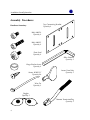
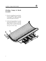
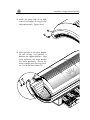
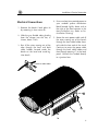
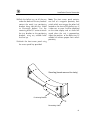
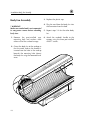
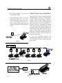
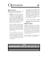
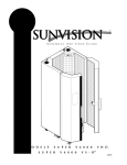
USER GUIDE
MODELS SUPER ZX 44 VS-Rª
SUPER ZX 44 VS-Rª3F
22414A
Limited Lifetime Warranty
SunStar® warrants your tanning unit to be free of structural defects in its material and workmanship,
under normal use, for its lifetime. SunStar will repair or replace, at their discretion, any defect to the
structure which affects the performance of the unit.
For 6 months from the date of purchase, SunStar will provide replacements for parts that prove to be
defective in material or workmanship. Acrylic shields, fluorescent lamps, and lamp starters are
excluded from this warranty. Labor will be covered for 30 days from purchase date. Normal wear,
damage from misuse or abuse, damage incurred in transit, or damage done by unauthorized repairs
or modifications are not covered by this warranty.
ETS, Inc. disclaims any implied warranty of merchantability or fitness for any period beyond the
expressed warranty. Some states do not allow limitations on how long an implied warranty lasts, so
the above limitations may not apply to you.
No one has authority to change or modify this Limited Lifetime Warranty in any respect. To obtain
service under the Limited Lifetime Warranty, contact ETS, Inc. at 1-800-228-6292, and ask for the
Technical Service Department.
ETS, Inc. SHALL NOT BE LIABLE FOR LOSS OF USE, LOSS OF TIME , INCONVENIENCE, RENTAL
OR SUBSTITUTE PRODUCTS, LOSS OF BUSINESS, LOSS OF INCOME, OR ANY OTHER INCIDENTAL OR CONSEQUENTIAL DAMAGES. Some states do not allow the exclusion or limitation of incidental or consequential damages, so the above limitation or exclusion may not apply to you.
This warranty gives you specific legal rights, and you may also have other rights which
may vary from state to state.
All warranty service must be performed by an authorized service person. If your tanning unit must
be returned for service, all freight charges must be at your expense. Contact your place of purchase
for the address of the SunStar Service Center nearest you. Proof of purchase is required to obtain
warranty service.
This warranty covers the original purchaser only. This warranty is void if the unit is modified
in any manner from its original design.
i
Welcome
Congratulations on your purchase of this technologically advanced sun tanning unit.
It has been designed to provide years of dependable service for you.
Please read all the instructions in this booklet before installing and using the unit.
Always be sure to observe all safety precautions.
Contents
Safety Information . . . . . . . . . . . . . . . . . . . . . . . . . .iii
Installation . . . . . . . . . . . . . . . . . . . . . . . . . . . . . . . .1
Unpacking and Inspection . . . . . . . . . . . . . . . . .1
Tools Required . . . . . . . . . . . . . . . . . . . . . . . . .2
Pre-Installation Planning . . . . . . . . . . . . . . . . . .3
Assembly Procedures . . . . . . . . . . . . . . . . . . . .4
Electrical Connections . . . . . . . . . . . . . . . . . . . .9
Bypass Plug . . . . . . . . . . . . . . . . . . . . . . . . . .13
Body Fan Assembly . . . . . . . . . . . . . . . . . . . . .14
Remote Connections . . . . . . . . . . . . . . . . . . .15
Operation . . . . . . . . . . . . . . . . . . . . . . . . . . . . . . . .17
Before You Tan . . . . . . . . . . . . . . . . . . . . . . . .17
Exposure Times . . . . . . . . . . . . . . . . . . . . . . .17
Using Your Sunbed . . . . . . . . . . . . . . . . . . . . .18
Care and Maintenance . . . . . . . . . . . . . . . . . . . . . . .20
Cleaning After Use . . . . . . . . . . . . . . . . . . . . .20
Thorough Periodic Cleaning . . . . . . . . . . . . . .20
Mechanical Inspection . . . . . . . . . . . . . . . . . .20
Replacing Lamps . . . . . . . . . . . . . . . . . . . . . .21
Troubleshooting . . . . . . . . . . . . . . . . . . . . . . . . . . . .24
Obtaining Service . . . . . . . . . . . . . . . . . . . .back cover
ii
safety Information
LABELING NOTICE: Labels are affixed on all systems to inform the user of possible dangers. Regulations are stated in
21 CFR, Section 1040.20, and require that all products manufactured after September 8, 1986 which use sunlamps
must display the following:
Ultraviolet radiation. Follow instructions. Avoid overexposure. As with natural sunlight, overexposure can cause eye and skin injury and allergic reactions. Repeated exposure may cause premature aging of the skin and skin cancer. WEAR PROTECTIVE EYEWEAR; FAILURE TO MAY RESULT IN SEVERE BURNS
OR LONGTERM INJURY TO THE EYES.
DANGER
Medications or cosmetics may increase your sensitivity to the ultraviolet radiation. Consult physician before using
sunlamp if you are using medications or have a history of skin problems or believe yourself especially sensitive to
sunlight. If you do not tan in the sun, you are unlikely to tan from the use of this product.
Minimum use distance from face tanner (if equipped) is 1 inch or 2.54 centimeters. Minimum use distance elsewhere is touching the clear plastic panels. Do not use without clear plastic panels (or wire grid for models using
wire grid) in place. Tanning normally appears after the first few sessions and maximizes after approximately four
weeks. Tan once or twice per week thereafter to maintain appearance. Frequency of sessions should be limited to
every other day. Persons already having a base tan may begin at advanced levels corresponding to the extent of
their base tan.
RECOMMENDED EXPOSURE TIMES IN MINUTES
Skin Type:
Week #
Session #
MAXIMUM EXPOSURE TIME IS 10 MINUTES
Week 1
1st-3rd
Week 2
4th-6th
Week 3
7th-10th
Week 4
11th-13th
Subsequent
Maximum
I Sensitive Skin (Burns easily and severely and does not tan.)
NOT RECOMMENDED FOR TANNING
II Light
(Burns easily and severely and tans minimally.)
2
4
6
8
10
III Normal
(Burns moderately and tans average.)
3
5
7
10
10
IV Dark
(Burns minimally, tans easily and above average.)
4
6
8
10
10
New lamps emit approximately 20% more ultraviolet radiation during the first 50 hours of operation. Recommended
tanning times should therefore be reduced by approximately 20% during that period.
WARNING: • Read the instructions booklet before using this sunlamp product. • To use, lie down under canopy
and pull down as far as adjustment will allow. All persons in the room should wear protective eyewear when lamps
are on. • Recommended eyewear: provided eyeshields (Lucas Products Super Sunnies or Intrexco No. 5635/1) or
equivalent eyewear as defined under 21 CFR 1040.20. Other types of eyewear may not provide adequate protection. • Disconnect power cord before attempting to clean, relamp, or engage in the maintenance of this product.
ONLY THE FOLLOWING LAMPS HAVE BEEN CERTIFIED FOR USE IN THE MODEL SUPER ZX44 VS-R™:
ACCELERATOR® VS-R™ Wolff® Model VAC75-T12-160W Bi-Pin
ACCELERATOR® VHO Wolff® Model ACC75-T12-160W BI-PIN
ONLY THE FOLLOWING LAMPS HAVE BEEN CERTIFIED FOR USE IN THE MODEL SUPER ZX44 VS-R™ 3F:
ACCELERATOR® VS-R™ Wolff® Model VAC75-T12-160W Bi-Pin
ACCELERATOR® VHO Wolff® Model ACC75-T12-160W BI-PIN
Philips Model HPA 400/30s or CosmoTech Model 23045 or CosmoTech 20046 (Facial Unit)
THIS EQUIPMENT MUST BE EARTH GROUNDED.
THIS PRODUCT IS IN CONFORMITY WITH PERFORMANCE STANDARDS FOR SUN LAMP PRODUCTS UNDER 21 CFR
PART 1040.20
iii
Installation
Unpacking and Inspection
Your sunbed comes in two cardboard cartons, one for the bench and one for the
canopy. Open the cartons and remove the
canopy and bench as follows.
The canopy box contains the canopy
unit, a pair of gas springs, and the body
fans.
The bench box contains the following
items:
• Bench Unit
The canopy and bench are each wrapped
in plastic. Pull away the plastic and, with
a helper, grasp the canopy and pull it
from the carton bottom, leaving the plastic wrap and the carton packaging. Next,
remove the bench from its box by lifting
it directly up and out of the box, clearing
the ballast trays located below. The ballast trays contain a positioning bolt which
protrudes from the back of them. You
may need to tilt the bench unit slightly to
clear the bolts when removing. Remove
the ballast trays from the pallet by removing the screws from the tray hold down
bracket. The trays are in proper orientation in the box. Note this when removing.
Note!
The cartons and other packing
materials are reusable, in the
unlikely event that you may find
it necessary to return your
sunbed.
• Box containing necessary assembly
hardware, panel key, canopy handle,
remote bypass, safety goggles, and
pillow
• Ballast trays
• Box containing the front access
panel.
Inspect these items, including the canopy
and bench, and make sure they are free
from any visible damage. Report the
extent of any damage to the transportation company.
Record the serial numbers of the canopy
and bench in the area provided on the
back of this manual. This information will
be required whenever you call customer
service.
Throughout this manual are pictures of, and references to, the
ballast tray assemblies. The ballast trays shown are for reference
only. Your ballast trays may differ slightly in componentry, however instructions are
identical for all units.
NOTE!
1
Installation-Tools Required
Tools Required
You will need the following tools to assemble your sunbed:
#2 Phillips Screwdriver
Adjustable Wrench
Utility Knife
2
Installation-Pre-Installation Planning
Pre-Installation Planning
Before you begin to assemble your sunbed, you should observe the following preinstallation considerations.
• Your sunbed operates from a 220V
AC source. The unit must be wired to
a dedicated circuit using an armored
cable. This cable and its associated
wires are to be provided by your electrician. See Electrical Connections for
the location of the power distribution
block and supply line routing.
• IMPORTANT! Voltage must be
below 230V AC or may require a
Buck Booster, contact ETS service at
the number on the back of this
guide. Use of a voltage source above
230V AC may reduce the life of some
components in your sunbed.
• The SunStar® ZX44 VS-R™ and
SunStar® ZX44 VS-R™ 3F require a
dedicated circuit capable of providing 60 Amp service. These units must
be hardwired directly to a junction
box.
• Make sure the room in which you
intend to use your sunbed is well
ventilated. Air from the room is used
to cool the sunbed, and a poorly ventilated room may cause the unit to
become hot and cause discomfort to
the user.
• Your sunbed is designed to operate in
an ambient room temperature of
80°F maximum and 70% relative
humidity.
• Place your sunbed no closer than 6"
from any wall. Make sure that curtains, drapes, and other room furnishings do not obstruct the airflow
into the end caps or out of the fan
opening areas.
• Proper assembly of your sunbed
requires three people. Plan to have a
couple of helpers assist you.
3
Installation-Assembly Procedures
Assembly Procedures
Tray Connecting Bracket
Quantity 4
Hardware Inventory
Bolt, M8X12
Quantity 2
Bolt, M8X35
Quantity 4
Pivot Stud
Quantity 2
Allen Wrench
Quantity 1
Hinge Washer Insert
Quantity 2
Screw, #10X1/2”
Quantity 26
Access Panel Key
Quantity 1
Wire Tie
Quantity 3
Goggles
Quantity 1
Remote TerminatorPlug
Quantity 1
4
Installation-Ballast Tray Assembly
Ballast Tray Assembly
1. Place the ballast tray assemblies
approximately where you want the
sunbed to be located. The completed tray assembly will be difficult to
move once assembled.
NOTE: The ballast trays are shipped in
their correct positions under the sunbed
bench. If these positions were not noted
during unpacking see the illustration
located on page 12.
2. Place the four tray connecting brackets (A) against the ballast trays as
shown, lining up the holes in the
bracket with the holes in the trays.
Fasten the brackets to the trays using
the #10X1/2” screws (B).
3. Electrically connect the trays together
by plugging the 15 pin connector from
the bench ballast tray into the canopy
ballast tray connector. (See page 12
detail A) Units with face tanners also
have a two pin connector in the same
location that must be connected.
B
A
5
Installation - Canopy to Bench Assembly
Attaching Canopy to Bench
Assembly
1. Place the sunbed bench over the ballast tray assembly as shown. The front
of the bench is the side without the
metal cover plate on the base.
2. Attach the hinge brackets (A) to the
rear ends of the bench (C) with the
M8x35 bolts (B). Leave one of the
brackets loose to allow for clearance
during the next few steps.
C
A
B
6
Installation - Canopy to Bench Assembly
3. Attach the pivot studs (A) to both
sides of the canopy (B) using the the
adjustable wrench. Tighten firmly.
B
A
4. With the help of two other people,
lift the canopy and position it
between the support brackets. Now
finish tightening the hinge bracket
left loose previously. Secure the
entire assembly with the hinge washers (A) and the M8x12 bolts (B).
A
B
7
Installation-Attaching Gas Springs
Attaching Gas Springs
A
1. Remove the locking clips (A) from the
ends of the gas springs. (See figure 1.)
2. Have a helper hold the canopy in its
full open position until the gas
springs and their locking clips are
installed.
3. Align open ends of gas spring ball
joints with pivot studs and gently tap
into place. Be sure the rod end is up
as shown. Replace locking clips.
IMPORTANT!
DO NOT lower
canopy until both gas springs are in
place and the locking clips are installed!
Failure to install locking clips may result
in the ball joints working loose, allowing
the canopy to fall, which may cause
serious injury!
4. Lift and lower the canopy a few
times to lubricate the seal inside the
spring. Keep the canopy closed
when not in use.
8
Figure 1
Installation- Electrical Connections
Electrical Connections
1. Remove the bench’s back plate (A)
by removing its four screws (B).
2. Slide the gray flexible tubing leading
from the canopy into the slot, as
shown, about 1 inch.
3. Run all the wires coming out of the
tube through the front and back
cable holders located under the
bench on the head end stand leg.
(See detail.)
4. Have an electrician provide power to
your sunbed’s power distribution
block located slightly above and to
the right of the hour counter in the
foot end ballast tray. (Refer to PreInstallation Planning)
5. Route the main power cable and all
the wires coming out of the bench
through the front cable holder located inside the foot end of the stand.
Continue to route the power cable
through the back cable holder and
then through opening (C) in the back
panel. Connect the sunbed directly
to a junction box.
Detail of cable holder
C
B
A
9
Installation-Electrical Connections
Unless otherwise noted refer to the ballast tray illustration on page 12 for the
following procedures.
9. Connect the end of the cable to the
timer box (figure 1, this page).
6. Mate the two colored cable assemblies coming from the bench to the
matching connectors on the foot end
ballast tray (detail B). Be sure to seat
the connectors fully. They will snap
together.
10. Verify that all ballast tray wires are
routed so that they cannot become
caught in the bench fan. If necessary
use the extra cable ties provided to
secure the wires. Be careful to allow
for ballast tray movement.
7. Mate the two colored cable assemblies coming from the canopy to the
matching connectors on the head
end ballast tray (detail C). Again, be
sure that the connection is secure.
8. Route the shielded low voltage cable
(D) leading from the canopy as
shown. Wire ties have been provided
to secure the cable in place where
noted on the diagram.
Note: This cable transmits digital communication between the main timer and the
timer display located in the canopy. It is
important to route the cable as shown to
minimize the possibility of electrical interference affecting the communication.
Figure 1
10
11. Underneath the bench, along side
the ballast trays, are restraining
cables (one each side). They are
coiled and held in place with plastic
wire ties which must be cut. Clip the
cables to the ballast trays where
shown (page 12).
Installation-Electrical Connections
12. Push the ballast tray set all the way
under the bed until the tray brackets
contact the metal, tray positioning
brackets along side the trays. (Refer
to illustration below.) Use the
remaining #10x1/2” screws to attach
the tray brackets to the positioning
brackets, using any suitable holes
that line up.
Note: The front access panel contains
one half of a magnetic proximity limit
switch which must engage the other half
located on the front of the ballast tray. If
it does not, an error 9 will be displayed
on the timer display and an alarm will
sound when the unit is powered-up.
Adjust the position of the ballast trays if
needed to achieve proper limit switch
proximity.
13. Attach the front access panel using
the access panel key provided.
Stand leg (bench removed for clarity)
Positioning Bracket
Restraining Cable
11
Installation-Electrical Connections
Low voltage cable (D)
Restraining cable hole
WIRE
TIE
WIRE
TIE
LOW
VOLTAGE
CABLE
12
Restraining cable hole
Installation-Bypass Plug
Bypass Plug
In the back of the foot end ballast tray is
a low voltage cable, coiled and wire tied,
with a small package of bubble wrap
around the end of it. Cut the wire ties
holding the coil and remove the bubble
wrap and static bag to reveal the remote
port board connected to the end of the
cable (see figure 1). Remove the two
small screws from the port board and
install the board on the inside of the
bench’s back panel using the screws, as
shown in figure 1 and arrow B in figure 2.
Connect the remote control bypass plug
(A) into the remote control port (B) as
shown in figure 2. The bypass plug can be
inserted into either port. Your sunbed will
not operate without the bypass plug or a
remote system connected. If you plan on
using a remote system refer to “Remote
Connections”.
Note: The remote control device is
optional and is not included with your
sunbed.
Caution: Remove the bypass plug when
using a remote system, except for the
case when the sunbed is at the end of a
T-Max® Manager series.
Replace the back plate with the four
screws removed earlier.
FIGURE 1
B
A
FIGURE 2
13
Installation-Body Fan Assembly
Body Fan Assembly
! WARNING!
Make sure sunbed unit is not connected
to any power source before attaching
body fans.
1. Remove the pre-installed cap,
mounting bolt and washers from
either end of the sunbed canopy.
2. Orient the body fan to the endcap so
that the metal stud on the bracket is
inserted into the hole in the endcap
beneath the mounting hole. Mount
the body fan using the removed hardware.
14
3. Replace the plastic cap.
4. Plug the cord from the body fan into
the connector from the bed.
5. Repeat steps 1-4 for the other body
fan.
6. Attach the sunbed’s handle to the
canopy, using the three pre-installed
#10x1” screws.
Installation–Remote Connections
Remote Connections
Your sunbed incorporates advanced circuitry
allowing it to connect and communicate with
most remote control systems. If a remote system is to be used, first determine whether the
remote system is a T-Max® System or a standard remote system operating with a control
relay. Follow the appropriate instructions for
your system type.
Warning: The remote connection is not
designed to supply or accept high voltage,
nor can it provide power to an external timer.
The sunbed’s remote interface circuitry operates on 5 volts, attempting to connect it to
any higher voltages will damage the sunbed
as well as void your warranty.
T-Max® 1A Remote System
The T-Max® 1A offers the same control as the
T-Max® Manager in single sunbed installations. For this, your 1A must be configured as
a “master”. If the 1A is not configured as a
master it will not work in this application.
After you have set the address, or “id” on the
sunbed simply connect the RJ-22 modular
cables, described in the T-Max® user’s guide,
directly into either port located on the back
of the sunbed and either port on the back of
the T-Max® 1A. If the T-Max® 1A and the
sunbed are more than 100 feet apart, terminators or SunStar® Remote Bypass plugs
should be installed in the unused ports. See
figure 1.
Setting the address
T-Max® Manager Remote System
The T-Max® Manager remote system offers
the ultimate in sunbed control, while allowing the tanner easy straightforward operation.
This system is ideal for multiple sunbed installations. Your sunbed is already configured to
directly connect to this system. The circuitry
inside your sunbed eliminates the need for
the T-Max® 1A when connecting to the TMax® Manager series. To connect your bed to
this system follow the instructions that came
with your remote system, noting figure 2 on
the next page. After you have set the address,
or “id” of each sunbed, simply connect the
RJ-22 Modular cable(s), described in the TMax® Manager manual, directly into the
port(s) located on the back of your sunbed.
You can place your sunbed at any location in
the series. Remember the last connection in
the series requires a T-Max® terminator plug
or SunstarTM bypass plug.
Before connecting your sunbed to the TMax® Manager or T-Max® 1A, the address or
“id” of your sunbed must first be set. The
auto-addressing feature of the latest T-Max®
Manager models is not compatible with this
sunbed. Set the “id” manually as described
below.
Setting the “id”
1. Verify that the sunbed display is indicating a “0”.
2. Press and hold the stop button located
on the sunbed display for three seconds and release. The display should
indicate an “id” number from 1 to 99.
3. If you are using a T-Max® 1A as your
remote the “id” of the sunbed must be
set to “1”. If you are using a T-Max®
Manager each sunbed must be
assigned a different “id”. To set the
“id” press the timer button until the
desired number is achieved.
15
Installation–Remote Connections
4. Press the stop button to return to the
normal display mode.
®
5. If you are using a T-Max 1A its “id”
must be set to “0.0”. See your 1A manual for instructions. Also refer to your TMax® 1A or Manager manuals to set
other functions such as delay time and
number of beds in the T-Max® Manager
series.
Figure 1
Remote systems using a Control Relay
Most non-T-Max® remote systems control the
sunbed by the use of a relay. The relay operates the sunbed by connecting and disconnecting a pair of wires leading from the
sunbed. Refer to the user’s manual provided
with your remote system to determine if it
operates in this way. To connect your sunbed
to this type of system a remote interface kit is
required. Call ETS at the phone number listed
on the back of this guide to obtain the kit.
Figure 3 below details a typical connection.
Follow the instructions provided with the kit
and from the remote’s manual to make the
necessary connections.
If you have questions consult the
Troubleshooting guide in this manual or call
ETS at the phone number listed on the back
of this guide.
Figure 2
16
Figure 3
Operation
Before You Tan
•
Some medication may increase your
sensitivity to ultraviolet light. It is recommended that you consult a physician
before using this sunbed if taking any
medication or if you suspect that your
skin might be especially sensitive to sunlight. Included with this manual is an
FDA booklet on medications that
increase sensitivity to light.
•
As with all electrical appliances, do not
operate this device near water or while
you are wet.
Before using your sunbed, please note
the following important precautions:
•
•
•
WARNING! Your sunbed is designed for
individual use. Only one pair of protective goggles is provided. Always wear
these or another approved pair of goggles. Regular sunglasses do not provide
adequate protection from ultraviolet
light. You should never look at the lamps
when turned on without wearing the
appropriate protective goggles.
Exposure Times
Your skin should be free of cosmetics,
tanning oils, or other body lotions prior
to tanning except for those specifically
made for use with tanning devices.
However, do not remove natural body
oils by bathing or showering immediately before tanning.
We recommend that you tan every other day,
following the tanning times in the exposure
schedule. Tanning normally appears after the
first few sessions and maximizes after approximately four weeks. Tan once or twice per
week thereafter to maintain appearance.
Persons already having a base tan may begin
at advanced levels corresponding to the
extent of their base tan.
Your hair should be free of gels, mousses, sprays, or other hair products prior to
tanning. These products can cause damage to the sunbed acrylic. As an alternative, a shower cap or towel can be worn
to keep treated hair away from the
sunbed surfaces.
Follow the guidelines for skin type and exposure times as shown in the table below.
RECOMMENDED EXPOSURE TIMES IN MINUTES
Skin Type:
Week #
Session #
MAXIMUM EXPOSURE TIME IS 10 MINUTES
Week 1
1st-3rd
Week 2
4th-6th
Week 3
7th-10th
Week 4
11th-13th
Subsequent
Maximum
I Sensitive Skin (Burns easily and severely and does not tan.)
NOT RECOMMENDED FOR TANNING
II Light
(Burns easily and severely and tans minimally.)
2
4
6
8
10
III Normal
(Burns moderately and tans average.)
3
5
7
10
10
IV Dark
(Burns minimally, tans easily and above average.)
4
6
8
10
10
17
Operation-Using Your Sunbed
Using Your Sunbed
When connected to the T-Max® Manager
A
B
C
A
Face tanner control - Turns face tanner on
and off during use. (Units equipped
with face tanner only)
B
Main lamp control - Turns body lamps on
and off during use. (Units equipped
with face tanner only)
C
Body fan control - Controls the speed of
the body fan during use.
D Body fan speed indicator - Indicates speed
of fan. (OFF - LOW - MED - HIGH)
E
Timer display - Displays remaining time.
F
Stop button - Turns lamps off.
G Timer button - Turns bed on. Timer display
shows remaining time. If a lesser time is
desired, repeatedly press timer button
until desired time is displayed.
D
E
F
G
1. Lift the canopy, lie down on the bench (face up),
and lower the canopy toward your body using
the canopy handle. For best results, position the
canopy as close as possible to your body. For
units with face tanners, maintain at least 1 inch
between the face tanner and your face.
2. Assuming the remote system has been set to
allow a pre-tanning delay time, the timer display
(E) will repeatedly flash the delay symbol “dL”
and then the remaining delay time. Press the
timer button (A) or wait until the delay time has
expired to begin the tanning session. The lamps
will turn on and the timer will begin to count
down. The sunbed will not allow a session time
greater than the sunbed’s maximum exposure
time. If the timer did not display a “dL”, see
Troubleshooting.
3. If a tanning time less than the displayed time is
desired repeatedly press the timer button to
decrease the remaining time.
4. When the timer reaches 0 the lamps turn off.
If you want to stop your session before time
expires press the stop button (F).
5. Raise the canopy by using the handle, do not
push-up on the acrylic shield. The cooling fans
run for 3 minutes after the lamps shut off to aid
in cooling the sunbed. The timer will then indicate “. .”, this is a reminder to clean the
sunbed. After the sunbed is cleaned press the
start button and the display will return to “0”.
18
Operation-Using Your Sunbed
If your sunbed is connected to a T-Max®
Manager remote system, turn to Using Your
Sunbed When connected to the T-Max®
Manager.
Using Your Sunbed
When configured as a stand alone unit or
when connected to a remote system using a
control relay.
A
B
C
A
Face tanner control - Turns face tanner on
and off during use. (Units equipped
with face tanner only)
B
Main lamp control - Turns body lamps on
and off during use. (Units equipped
with face tanner only)
C
Body fan control - Controls the speed of
the body fan during use.
D Body fan speed indicator - Indicates speed
of fan. (OFF - LOW - MED - HIGH)
E
Timer display - Displays remaining time.
F
Stop button - Interupts timer circuitry. You
may restart with remaining time within
10 seconds. After 10 seconds timer
resets to 0 minutes.
G Timer button - Turns bed on. Timer display
shows remaining time. If a lesser time is
desired, repeatedly press timer button
until desired time is displayed.
D
E
F
G
1. Lift the canopy, lie down on the bench
(face up), and lower the canopy toward
your body using the canopy handle. For
best results, position the canopy as close as
possible to your body. For units with face
tanners maintain at least 1 inch between
the face tanner and your face.
2. Start the sunbed by pressing the timer button (G), located at the head end of the
canopy. The lamps will turn on and the
timer display (E) will indicate the session
time remaining. If less than the maximum
tanning time is desired, repeatedly press
the timer button (G) until the desired time
is indicated.
3. When the timer reaches 0, the lamps will
turn off. If you want to stop your session
before time expires press the stop button
(F). The sunbed will then allow you ten
seconds to reactivate the bed with the
unused time. After ten seconds the timer
system resets back to 0 minutes.
4. Raise the canopy by using the outer edge of
the canopy, do not push-up on the acrylic
shield. The cooling fans run for 3 minutes
after the lamps shut off to aid in cooling the
sunbed.
19
Care & Maintenance
Cleaning After Use
Cleaning the Canopy and Bench
Clean and disinfect your tanning bed’s
bench and canopy after each use. Use a
non-abrasive disinfectant cleaner that
does not contain ammonia or ammonia
derivatives. Ammonia may damage the
acrylic shield. Spray the acrylic lightly
with disinfectant and wipe dry with a
clean soft cloth. We recommend
SunQuest® disinfectant and SunQuest®
acrylic cleaner.
Step 1. Remove the acrylic shields and
lamps as described in Replacing
Lamps.
Step 2. With a soft cloth, wipe the entire
length of each lamp to remove
any film buildup.
Step 3. Clean both sides of the acrylic
shields with a non-ammonia disinfectant cleaner.
Step 4. Wipe the reflectors with a clean
damp cloth.
Step 5. Re-install the lamps and acrylic
shields.
Thorough Periodic Cleaning
Introduction
The cooling fans draw air through the bed
and over time will cause a dust buildup in
the sunbed’s air filters. Clean these filters
monthly. The filters are located on the
bottom of both ends of the bench and on
the canopy underneath the top covers.
They are held in place by velcro strips.
Clean the filters using a vacuum or with
mild soap and water.
Occasionally, dust will pass by the filters
causing a buildup on your sunbed’s
lamps and reflectors. This will reduce the
tanning effectiveness of the bed. When a
dust buildup is observed, it is necessary to
thoroughly clean the inside of the bench
and canopy.
Warning! Disconnect sunbed from electrical power before cleaning.
20
Mechanical Inspection
Your tanning bed has been built for years
of service. To ensure trouble-free operation throughout its life, inspect the unit’s
mechanical integrity every 400-500 hours
of use.
• Inspect the unit’s fasteners verifying
that all are firmly in place.
• Inspect gas springs for signs of wear.
Gas springs that will not steadily hold
up the canopy should be immediately replaced. See Troubleshooting.
• Inspect the AC power cable and its
connections.
• Inspect the acrylic. Broken, cracked or
badly scratched acrylics should be
immediately replaced.
Care & Maintenance-Replacing Lamps
Removing/Replacing Acrylic Shields
Replacing Lamps
Introduction
Your sunbed has an hour meter located in
the foot end of the ballast tray which
keeps track of how many hours the
sunbed has been in operation. Use this
meter to determine when your tanning
lamps should be replaced. To be assured
of maximum tanning effectiveness,
change the lamps after approximately
800-1000 hours of use. Tanning will continue after this time but at a slower rate.
To ensure trouble-free operation of your
sunbed, replace the lamp starters whenever the lamps are replaced.
Warning! Disconnect sunbed from electrical power before servicing.
Step 1. The acrylic shields in the canopy
and bench are both secured in
place by acrylic covers which
run the length of the canopy and
bench, both front and back. To
remove the acrylic shield gently
pry up on acrylic side of the
cover, working your way along
the full length of the acrylic
shield until the cover is released.
Repeat for the other cover. The
edges of the acrylic are now
exposed.
Step 2. Remove the sprung steel acrylic
center shims from both ends of
the acrylic, front and back. (See
figure 1, at left)
Step 3. Remove the control assembly
from the canopy acrylic by sliding it upward until its clips disengage. (See figure 2, below)
CENTER SHIM
Figure 1
CANOPY ACRYLIC
Step 4. Slide the acrylic shield toward
the head or foot end of the bed.
The short edge of the acrylic
shield at the opposite end will
now be visible. Remove the
shield by lifting from this end.
CLIPS
Step 5. R e p l a c e
the acrylic shield
by reversing the
above steps.
Figure 2
CONTROL ASSEMBLY
21
Care & Maintenance-Replacing Lamps
Removing/Replacing Lamps
Recommended Replacement Lamps
After removing the acrylic shield, replace
lamps as follows:
We recommend using the lamps specified below. Use of uncertified lamps is a
violation of federal regulations and will
void your warranty. These lamps have an
average life of 800-1000 hours of effective tanning use. Lamps used longer than
that begin to lose their effectiveness even
though they will continue to light.
Step 1. Grasp the lamp at one end and
at the middle, then turn the
lamp a quarter turn. The lamp
may then be gently removed
from its holder.
Step 2. To re-install a lamp, insert the
pins located on the ends of the
lamp into the slots on top of the
lamp holder and turn the lamp a
quarter turn.
Only the following lamp types have been certified for use in your SunStar Solarium
Application
Lamp Model Number
Super ZX44 VS-R™
ACCELERATOR® VS-R™ Wolff® Model VAC75-T12-160W VS-R Bi-Pin
ACCELERATOR® VHO Wolff® Model ACC75-T12-160W BI-PIN
Super ZX44 VS-R™ 3F
ACCELERATOR® VS-R™ Wolff® Model VAC75-T12-160W VS-R Bi-Pin
ACCELERATOR® VHO Wolff® Model ACC75-T12-160W BI-PIN
(Facial unit)
22
Philips Model HPA 400/30s
CosmoTech Model 23045
CosmoTech Model 20046
Care & Maintenance-Replacing Lamps
Removing/Replacing Face Tanner Lamp
on F Models
After removing the canopy acrylic shield,
replace the face tanner lamp as follows:
Step 1. Support the face tanner assembly with your hand while
unscrewing the two retaining
screws. The face tanner glass
casing will now swing downward.
Step 2. The lamp can now be
exchanged. The lamp holders
are equipped with spring contacts which enables the lamp to
be removed easily. Remove the
old lamp and discard. Install the
new lamp, using a clean cloth or
paper towel. Ensure that the
lamp is firmly seated in the lamp
holders.
Note! Never take hold of the lamp such
that your fingers are in contact with the
lamp glass. Finger oils will greatly reduce
the lamp’s operational life.
Step 3. Gently close the face tanner glass
casing and lock it closed with the
screws. Ensure that the screws
firmly secure the glass casing.
Warning! Never turn the equipment on
while the face tanner is disassembled or
when the glass filters have been removed.
The direct light can cause severe injury to
the eyes and to other areas of the body.
Immediately discontinue use of this
equipment if the face tanner glass is broken or if any unfiltered light can be seen
escaping the face tanner assembly.
RETAINING
SCREWS
23
Troubleshooting
Problem
Solution
Sunbed not tanning
1.
2.
3.
4.
Lamps fail to light and timer
display is blank
1. Make sure the unit is connected to a power source.
2. Check source of AC power. Reset circuit breaker or
replace fuse.
Timer display changes to indicate a tanning time after the
timer button is pressed but
lamps do not come on
1. Bypass plug is not installed see Electrical Connections.
2. A non-SunStar® bypass has been used. See Electrical
Connections.
3. If remote is being used, other than T-Max® Manager,
the external timer may not be activated, or...
4. remote wiring is incorrect, see the instructions provided with the remote interface kit.
My bed is connected to the
T-Max® Manager remote system and when the delay time
has expired the timer display
starts counting down but the
bed lights do not come on
Clean sunbed, see Thorough Periodic Cleaning.
Ensure supply voltage is between 208 and 230V AC.
Replace lamps if lamp hours are greater than 800hrs.
Replace acrylic.
The auto start feature of the remote system is disabled,
see the instructions provided with your remote system.
My bed won’t work with the
T-max® Manager remote systems
1. The sunbed must first be set to a unique address see
Remote Connections.
2. The bypass or terminator plug may be installed in the
series in an inappropriate location. Plug the bypass
plug only into the bed at the end of the series.
Timer display continues to
show a 0 after the timer button is pressed
1. T-Max® Manager remote system has not yet been set.
2. Sunbed address is not set correctly see Remote
Connections.
The last minute of tanning
time does not count down
from 59 seconds, but some
time less than 59 seconds
24
If the timer button has been pressed to decrease tanning time during the session, the time expired in the
current minute is subtracted from the last minute.
Troubleshooting-Problems/Solution Chart
Problem
Solution
One or more lamps fail to light
1. Check that lamp is installed correctly.
2. Switch unlit lamp with a lamp that lights, if new lamp
lights and old lamp still does not, replace old lamp.
The face tanners will not
come on
1. Face tanner operation is initially delayed by 5 seconds.
2. Face tanners will not re-light until cooled.
3. Replace face tanner lamp, see Removing/Replacing
Face Tanner Lamp on F Models.
The canopy will not stay up
NOTE: Gas springs are manufactured to hold the canopy
in its fully open position as well as allow it to rest fully
closed. If left open for an extended period of time
some creep down may occur. This is considered normal. Keep the unit closed when not in use. If the
canopy will not stay fully open when raised...
1. raise and lower the canopy a few times to lubricate
internal gas spring seals.
2. replace gas springs.
My bed is connected to a TMax® remote system but I am
having trouble getting into
“id” mode.
My bed, connected to a TMax® Manager, did not display
“dL” but does indicate:
“0”.
You have probably attempted to connect your sunbed
to the remote system already. Disconnect the remote
plug(s) from the ports at the back of the sunbed, wait
90 seconds and try again.
1. Remote device has not been set.
2. The sunbed has not been connected to the remote
system, see Remote Connections.
a tanning time and the
lamps have come on.
1. Delay time of T-Max® Manager has not been set.
2. Delay time has expired and session has begun.
a tanning time but the
lamps have not come on.
Auto start function of T-Max® Manager has been turned
off. Press the timer button to turn on lamps
Timer display is indicating Er 1
Body lamps are on when they should be off, have
service technician check the contactor.
Timer display is indicating Er 2
Body lamps are off when they should be on, have
servicer check contactor and its wiring from the main
timer box.
25
Troubleshooting-Problems/Solution Chart
Problem
Solution
Timer display is indicating Er 3
Bench lamps are on when they should be off, have
service technician check the contactor.
Timer display is indicating Er 4
Bench lamps are off when they should be on, have
service technician check the contactor and its wiring
from the main timer box.
Timer display is indicating Er 5
Not currently used
Timer display is indicating Er 6
Not currently used
Timer display is indicating Er 7
Face Tanner contactor is closed when it should be
open, have service technician check the contactor.
Timer display is indicating Er 8
Face Tanner contactor is open when it should be
closed, have service technician check the contactor
and its wiring from the main timer box.
Timer display is indicating Er 9
Ballast Drawer is open or drawer switch is broken.
Timer display is indicating Er 10
Timer computer is in an illegal state, reset power to
correct, replace main timer if error reoccurs.
Timer display is indicating Er 11
Timer computer is in an illegal state, reset power to
correct, replace main timer if error reoccurs.
Timer display is indicating Er 12
Timer computer is in an illegal state, reset power to
correct, replace main timer if error reoccurs.
Timer display is indicating Er 13
Timer computer is in an illegal state, reset power to
correct, replace main timer if error reoccurs.
Timer display is indicating Er 14
Timer display is indicating Er 15
26
The timer display is not responding;
1. Check cable to display.
2. Replace display assembly.
3. Replace main timer box.
Timer computer is in an illegal state, reset power to
correct, replace main timer if error reoccurs.
CALL FOR SERVICE OR
QUESTIONS:
1•800•449•3605
6270 Corporate Drive
Indianapolis, IN 46278-2900
Record this information for ease of service
Date Purchased
Canopy Serial Number
Bench Serial Number