1
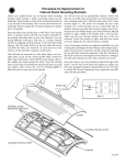
Introduction
Hello, and thank you for choosing the Light
Shuttle tanning unit. The Light Shuttle represents
one of the finest tanning units in the industry.
Designed for durability and tanning efficiency,
the Light Shuttle should exceed your expectations for ease of use and operation.
Please take the time now to read through this
user manual in order to familiarize yourself with
the unit before assembly and operation. The
manual has been carefully written to ensure that
you, the user, will have all the information you
need to set up and operate the Light Shuttle.
However, a team of trained service personnel at
ETS, Inc. is available to assist you with any questions or problems you may encounter. Feel free
to contact them at the number on the back of
this user manual.
We hope you enjoy your experience with the
Light Shuttle tanning system.
Table of Contents
Safety Information . . . . . . . . . . . . . . . . . . . . . . . . .ii
Pre-Installation Considerations . . . . . . . . . . . . . . .iii
Getting Started . . . . . . . . . . . . . . . . . . . . . . . . . .iv
Visual Inspection . . . . . . . . . . . . . . . . . . . . . . . . . . . . . . . .iv
Tools Needed . . . . . . . . . . . . . . . . . . . . . . . . . . . . . . . . . .iv
Setup . . . . . . . . . . . . . . . . . . . . . . . . . . . . . . . . . .1
Unpacking . . . . . . . . . . . . . . . . . . . . . . . . . . . . . . . . . . . . .1
Assembly . . . . . . . . . . . . . . . . . . . . . . . . . . . . . . . . . . . . . .2
Operation . . . . . . . . . . . . . . . . . . . . . . . . . . . . . .7
Before You Tan . . . . . . . . . . . . . . . . . . . . . . . . . . . . . . . . . .7
Exposure Times . . . . . . . . . . . . . . . . . . . . . . . . . . . . . . . . .7
Seat Adjustment . . . . . . . . . . . . . . . . . . . . . . . . . . . . . . . .8
Using the Light Shuttle . . . . . . . . . . . . . . . . . . . . . . . . . . . .9
Remote Operation . . . . . . . . . . . . . . . . . . . . . . . . . . . . . .10
Care and Maintenance . . . . . . . . . . . . . . . . . . . .12
Cleaning After Use . . . . . . . . . . . . . . . . . . . . . . . . . . . . . .12
Thorough Periodic Cleaning . . . . . . . . . . . . . . . . . . . . . . .12
Mechanical Inspection . . . . . . . . . . . . . . . . . . . . . . . . . . .12
Lamp Removal . . . . . . . . . . . . . . . . . . . . . . . . . . . . . . . . .13
Troubleshooting . . . . . . . . . . . . . . . . . . . . . . . . .19
Warranty Information . . . . . . . . . . . . . . . . . . . . .21
i
Safety Information
LABELING NOTICE: Labels are affixed on all systems to inform the user of possible dangers. Regulations are stated in 21 CFR, Section
1040.20, and require that all products manufactured after September 8, 1986 which use sunlamps must display the following:
Ultraviolet radiation. Follow instructions. Avoid overexposure. As with natural sunlight, overexposure can
cause eye and skin injury and allergic reactions. Repeated exposure may cause premature aging of
the skin and skin cancer. WEAR PROTECTIVE EYEWEAR; FAILURE TO MAY RESULT IN SEVERE BURNS OR LONGTERM INJURY TO
THE EYES. Medications or cosmetics may increase your sensitivity to the ultraviolet radiation. Consult a physician before
using sunlamp if you are using medications or have a history of skin problems or believe yourself especially sensitive to
sunlight. If you do not tan in the sun, you are unlikely to tan from the use of this product.
DANGER
WARNING: Do not use without filter glass panels in place. To use, sit down and move chair forward. Always maintain at
least 10 inches (25.4 centimeters) between your face and the face tanners. Other positions may result in overexposure to
parts of your body. All persons in the room should wear protective eyewear when lamps are on. Recommended eyewear:
Provided eyeshields (Lucas Products Super Sunnies or Intrexco No, 5635/1) or equivalent eyewear as defined under 21 CFR
1040.20. Other types of eyewear may not provide adequate protection.
RECOMMENDED EXPOSURE TIMES IN MINUTES
Skin Type:
MAXIMUM EXPOSURE TIME IS 10 MINUTES
Level 1/Week 1
1st-3rd Sessions
Level 2
I Sensitive Skin (Burns easily and severely and does not tan.)
Level 3
Level 4
Subsequent
Maximum
NOT RECOMMENDED FOR TANNING
II Light
(Burns easily and severely and tans minimally.)
2
4
6
8
10
III Normal
(Burns moderately and tans average.)
3
5
7
10
10
IV Dark
(Burns minimally, tans easily and above average.)
4
6
8
10
10
Untanned persons should not tan on consecutive days during their first week of tanning. Never tan more than once a day. Tanning normally appears after the first few sessions and maximizes after approximately four weeks. Tan once or twice per week
thereafter to maintain appearance. Persons already having a base tan may begin at advanced levels corresponding
to the extent of their base tan.
ONLY THE FOLLOWING LAMPS HAVE BEEN CERTIFIED FOR USE IN THIS EQUIPMENT:
Facial Lamp - KBL 2000, Heraeus Model BQ 2837 Z4
Hand Lamp - KBL 400, Heraeus Model BQ 407 Z4
CAUTION: Disconnect power before attempting to clean, relamp, or engage in the maintenance of this product.
THIS UNIT MUST BE EARTH GROUNDED.
THIS PRODUCT IS IN CONFORMITY WITH PERFORMANCE STANDARDS FOR SUNLAMP PRODUCTS UNDER 21
CFR PART 1040.20
ii
Pre-Installation Considerations
Before you install your sunbed, you should observe the following pre-installation considerations.
• READ ALL INSTRUCTIONS BEFORE OPERATING UNIT.
• The Light Shuttle requires a dedicated 208V
AC, 3-phase circuit capable of providing 40
Amps per phase. This unit must be hardwired directly to a junction box using the
armored cable provided. The unit must be
earth grounded.
• This unit must be used in an enclosed area so
passersby will be shielded from the tanning
light.
• Make sure the room in which you intend to
use your sunbed is well ventilated. Air from
the room is used to cool the unit. A poorly
ventilated room may cause the unit to
become overheated and cause undesirable
operation.
• Your sunbed is designed to operate in an
ambient room temperature of 80°F maximum and 70% relative humidity. Excessive
humidity and/or room temperature may
cause decreased tanning power and tanning
performance.
• Place the Light Shuttle no closer than 6" from
any wall. Make sure that curtains, drapes,
and other room furnishings do not obstruct
the airflow into or out of the unit.
• Due to the size and weight of the unit, proper installation requires four people. Plan to
have a few helpers assist you.
IMPORTANT! Voltage must be below 230V AC or may require a Buck Booster, contact ETS, Inc. service at the number on the back of this user manual. Use of a voltage
source above 230V AC may reduce the life of some components in your sunbed.
iii
Getting Started
Visual Inspection
Tools Needed
Note! The crate your sunbed arrived in is
reusable if you need to transport the unit in the
future.
Before you begin assembling your Light Shuttle,
you will need to gather a few tools.
After opening the crate and unwrapping all parts
(refer to the section on Unpacking), inspect them
for any visible damage which may have occurred
during shipping. Note any damage and contact
customer service.
Record the serial number of the unit, located on
the back of the unit near the power cord, in the
area provided on the back of this manual. This
information will be required when you call customer service.
#2 Phillips Screwdriver
Utility Knife
1/2” Wrench,
17mm Wrench and
Adjustable Wrench
6mm Allen (Hex) Wrench
iv
Setup
Unpacking
Your Light Shuttle is delivered as a tightly packed
unit. This section will help you identify the parts
of the unit as they are unpacked. Refer back to
this section if you ever need to move the Light
Shuttle.
Loosen the cargo straps that hold the unit in
place. Follow the illustrations at right if you have
difficulty. The straps may then be removed and
placed aside. Next, cut the plastic cover that is
over the entire unit. By cutting carefully around
the base of the unit you can use this plastic “bag”
to cover the Light Shuttle when needed.
The seat is leaning up against the main unit. Put
it in an out of the way place to keep it from being
damaged. Now, unwrap the main standing unit.
In the middle of the base is a bundle of accessories strapped together with plastic strapping.
Cut the strapping and remove the desiccator pillows (for moisture absorption) taped to the top of
the stack of bubble-wrapped accessories.
On top are the two base grills. Next is the large,
bevelled ballast cover. Then remove the seat
base. The seat base is rather heavy and should
be lifted by two people. Under the seat base is
the safety tray. Unwrap all parts and set them
aside for later.
Base Grills
Ballast Cover
The base of the Light Shuttle is kept from shifting
by three wooden blocks. Use a Torx T-25 screwdriver bit and drill to remove them. Your Light
Shuttle is now ready to be moved into place and
assembled.
Seat Base
Safety Tray
1
SETUP - assembly
Assembly
As mentioned earlier, the Light Shuttle’s base
unit is heavy and requires four people to lift it
from its crate bottom. Fortunately, once the base
is put in place, assembly can be performed without moving it again. For this reason, plan where
you want to put the unit before you begin
assembly,
referring
to
Pre-Installation
Considerations for placement planning.
BOLTS
The ballast tray is attached to the base by four
bolts, two each side (see picture at right).
Remove these bolts and put the ballast tray
where you want the Light Shuttle to sit. Position
the tray no closer than 6” from the wall and
remember its orientation to the main unit.
Now lift the main unit from the skid and put it in
place with respect to the ballast tray. There are
two loose wire harnesses coming out from
underneath the main base, one armored cable
that will connect to the seat unit and one 10-pin
connector that plugs into the ballast tray. Be
careful not to damage these cables or get them
caught beneath the unit.
Reattach the ballast tray to the base with the four
bolts removed earlier. Remember, put the bolt
through the hole and fasten it with one flat washer, one lock washer and the nut, in that order.
Plug the male 10-pin connector from the base
unit into the female connector on the ballast tray,
as shown at right. Connect the green grounding
plug to the tab next to the 10-pin connector.
2
GROUND WIRE
10-PIN CONNECTOR
SETUP - assembly
Fastener Inventory
Open the small packet wrapped in foam wrap.
Inside this packet is a zip-close bag with a few
bolts and washers, as well as some other important accessories. In addition to some touch-up
paint you should have the following items:
#8 x 1/2” Phillips Pan Head Screw
Quantity - 2
M8x20 Hex Head Bolt
Quantity - 2
M8 Flat Washer
Quantity - 2
M8 Lock Washer
Quantity - 2
M6x12 Phillips Oval Countersunk Head
Machine Screw
Quantity - 8
T 315mA 250V (5x20mm) European style fuse
[400mA 250V (5x20mm) time delay (Slo-Blo)
American style] Quantity - 2
T 3.15A 250V (5x20mm) European style fuse
[4A 250V (5x20mm) time delay (Slo-Blo)
American style] Quantity - 2
T 5A 500V (1/4 x 1 1/4”) European style fuse
[6A 500V (1/4 x 1 1/4”) time delay (Slo-Blo)
American style] Quantity - 1
3
SETUP - assembly
Install the ballast cover over the ballast tray with
the two #8 x 1/2” Phillips screws.
Now place the seat base into position as shown
at right. There are two bolts coming up from the
main unit base where the seat base will rest.
These bolts will fit into the seat base’s side tubes
when the seat base is put in place.
SIDE TUBE COVERS BOLTS
Underneath the front of the seat base are two
metal tabs with holes in them which must line up
with the metal tabs on the main unit base. This
is where the two bases connect with the M8x20
Hex Head bolts. Put one lock washer and one
flat washer (in that order) onto the bolt and fasten the seat base to the main base as shown.
4
SETUP - assembly
An armored cable runs out from under the main
base which connects to the seat base with a
black connector labelled ‘X9’. Plug the connector into its mating connector on the seat base
where shown at right. Make sure the connection
is secure. Place the safety tray under the seat
base.
TAB
The base grills install on either side of the seat
base to hide the electric motor which moves the
seat forward and back. Install the grill, as shown,
with the M6x12 Raised Countersunk Head
Screws (indicated by arrows below) in the four
metal tabs (see photo above). You may have to
lift the grills slightly in order to put the screws
through a full hole in the grill mesh pattern.
5
SETUP - assembly
Unwrap the seat, if not already done. Turn it
over and remove the four hex socket bolts and
their associated lock washers, with a 6mm Allen
(Hex) wrench.
Turn the seat back over and connect it to the seat
bracket with the hex socket bolts and washers
removed previously. Stickers are on the seat
bracket to help with positioning.
Refer to the section on seat adjustment in
Operation to position the chair.
Have an electrician connect the main power cord
to a 208V AC 3-phase dedicated circuit as outlined in Pre-Installation Considerations.
6
Operation
Before You Tan
Exposure Times
Before using your Light Shuttle, please note the
following important precautions:
Follow the tanning times in the exposure schedule below to determine the amount of time you
should tan. This schedule is a recommendation
for the duration of your tanning session according
to your skin type. Untanned persons should not
tan on consecutive days during their first week of
tanning. Never tan more than once a day.
Tanning normally appears after the first few sessions and maximizes after approximately four
weeks. Tan once or twice per week thereafter to
maintain appearance. Persons already having a
base tan may begin at advanced levels corresponding to the extent of their base tan.
• This unit was designed for single person use.
For this reason only one pair of protective
eyewear is provided. However, all persons in
the room must wear protective eyewear
when the unit is in operation.
• Your skin should be free of cosmetics, tanning oils, or other body lotions prior to tanning except for those specifically made for
use with tanning devices. However, do not
remove natural body oils by bathing or showering immediately before tanning.
• Some medication may increase your sensitivity to ultraviolet light. It is recommended
that you consult a physician before using this
sunbed if taking any medication or if you suspect that your skin might be especially sensitive to sunlight. Included with this manual is
an FDA booklet on medications that increase
sensitivity to light.
• As with all electrical appliances, do not operate this device near water or while you are
wet.
RECOMMENDED EXPOSURE TIMES IN MINUTES
Level 1/Week 1
1st-3rd Sessions Level 2
Skin Type:
I
II
III
IV
Sensitive Skin
Light
Normal
Dark
MAXIMUM EXPOSURE TIME IS 10 MINUTES
(Burns easily and severely and does not tan.)
(Burns easily and severely and tans minimally.)
(Burns moderately and tans average.)
(Burns minimally, tans easily and above average.)
Level 3
Level 4
NOT RECOMMENDED FOR TANNING
2
4
6
8
3
5
7
10
4
6
8
10
Subsequent
Maximum
10
10
10
7
OPERATION - seat adjustment
Seat Adjustment
Adjust the seat back with the knob at the side of
the seat, under the armrest.
The armrests have internal stops allowing them
to be positioned at a comfortable level. Adjust
the angle of the armrests by pushing the buttons
at the end of the armrest.
PUSH
8
OPERATION - using your sunbed
Using the Light Shuttle
(If you plan to use a remote system with your Light Shuttle refer to the section on Remote Operation
before using the unit.)
HIGH
OFF
LOW
TIMER CONTROLS
SEAT CONTROL
A “Start/Stop” button - Starts session time and
interrupts timer.
B “Set” button - Sets time of session. Timer display shows remaining time.
C Timer display - Shows remaining session
time.
D Seat control - Moves the seat forward and
back.
E Cooling Fan control - Controls the speed of
the body cooling fan.
COOLING FAN CONTROL
1. Sit in the chair and face the tanners. Adjust
the seat back and armrests as described earlier in the Seat Adjustment section. Put on
protective eyewear.
2. Set the session time by pressing the Set button repeatedly until the desired time is displayed (refer to Exposure Times). Press the
Start/Stop button. The lamps will turn on
and the timer display will indicate the session
time remaining.
3. With the unit running, you can move the seat
forward or backward by pressing the up or
down arrow button. Always maintain at least
10” between your face and the tanners.
4. When the timer reaches 0, the lamps will turn
off and the seat will move backwards to its
initial position. If you want to stop your session before time expires press the Start/Stop
button. The timer will continue to count
down with the lamps off. You may resume the
session by pressing the button again.
5. The cooling fans run for about 3 minutes after
the lamps shut off to aid in cooling the unit.
The timer display will show “..” as a reminder
9
OPERATION - remote operation
Remote Operation
Warning: The remote connection is designed
to connect only to a T-Max® Manager or T-Max®
1A’s. The connection cannot supply or accept
high voltage, nor can it provide power to an
external timer.
Looking at the face tanner side of the unit, the
remote ports are located at the back of the base,
to the right of the ballast tray.
T-Max® Manager remote system
The T-Max® Manager remote system offers the
ultimate in tanning equipment control, while
allowing the tanner easy straightforward operation. This system is ideal for multiple sunbed
installations. To connect your Light Shuttle to this
system follow the instructions that came with
your remote system, noting figure 2 on the next
page. After you have set the address of each suntanning unit, simply connect the RJ-22 modular
cable(s), described in the T-Max® Manager manual, directly into the port(s) located on the back
of the Light Shuttle. You can place the Light
Shuttle at any location in the series. Remember
the last connection in the series requires a TMax® terminator plug.
10
T-Max® 1A remote system
The T-Max® 1A offers the same control as the TMax® Manager in single unit installations. For
this, your remotely located 1A must be configured as a “master”. If the remote 1A is not configured as a “master” it will not work in this
application.
After you have set the address on the remotely
located T-Max® 1A and the Light Shuttle simply
connect the RJ-22 modular cables, described in
the T-Max® user’s guide, directly into either port
located on the back of the Light Shuttle and
either port on the back of the remotely located TMax® 1A. If the T-Max® 1A and the Light Shuttle
are more than 100 feet apart, terminators should
be installed in the unused ports. See figure 1.
OPERATION - remote connection
Setting the address
Before connecting your Light Shuttle to the TMax® Manager or remotely located T-Max® 1A,
the address of the Light Shuttle must be set. To
do this...
1. Remove power from the Light Shuttle.
2. Press and hold the Start/Stop button on the
Light Shuttle’s T-Max® 1A.
3. Apply power to the Light Shuttle, while still
holding the Start/Stop button.
4. The display should show “0.0” indicating an
address of 00. Press and hold the Set button
to count up to the desired address for the
Light Shuttle (00-254). Set each T-Max® 1A
to a unique address. The period between
the numbers will flash to indicate an address
over 100.
If you are using a remotely located T-Max® 1A as
the remote system, set the Light Shuttle to “0.1”.
Refer to your T-Max® manual for more detailed
instructions
FIGURE 1
FIGURE 2
11
Care and Maintenance
Cleaning After Use
Mechanical Inspection
Clean and disinfect your tanning unit’s hand tanner plates and seat after each use. For the hand
tanner plates, use a non-abrasive disinfectant
cleaner suitable for cleaning glass. Use a clean
soft cloth moistened with the cleaner to wipe the
hand tanning surfaces. We recommend
SunQuest® disinfectant. To clean the seat, use a
clean soft cloth moistened with water and a
small amount of delicate fabric soap. NEVER
SPRAY THE SEAT WITH ANY TYPE OF SOLVENT, GLASS CLEANER OR OTHER CAUSTIC
CLEANING SOLUTION.
Your Light Shuttle has been built for years of service. To ensure trouble-free operation throughout its life, inspect the unit’s mechanical integrity every 200 hours of use.
Thorough Periodic Cleaning
The cooling fans draw air through the unit and
over time will cause a dust buildup on the unit’s
bulbs and filter glass. You will need to clean the
interior of the unit, including vacuuming the
fans, and wipe the bulbs and filter glass periodically to keep the Light Shuttle functioning optimally. It is recommended you clean the unit
every 100 hours of operation or whenever you
see dust accumulate inside the unit. Procedures
for these operations are explained on the next
few pages.
• Inspect the unit’s fasteners verifying that all
are firmly in place.
• Inspect the AC power cord and its connections.
• Inspect the filter glass. Broken, cracked or
badly scratched glass should be immediately
replaced.
• Verify that all moving parts operate smoothly,
including the seat adjustment mechanisms
and fans.
• Lubricate the drive spindle of the seat motor
with copper paste if needed (whenever the
tanning lamps are replaced is recommended).
CAUTION!
DISCONNECT POWER BEFORE
ATTEMPTING TO CLEAN, RELAMP,
OR ENGAGE IN THE
MAINTENANCE OF THIS PRODUCT.
12
CARE AND MAINTENANCE - lamp removal
Lamp Removal
Your Light Shuttle utilizes five very powerful
lamps. Over time, their power decreases and
you will have to replace them. Recommended
replacement time is every 500 hours of use. The
unit is equipped with an hour counter to tell you
how long the unit has been used.
The hour counter
Under the left hand tanner, at the base of the
unit, is a removable panel. It is held in place by
two turn latches. Use a flat bladed screwdriver to
turn the latches 1/4 turn. The plate will then
swing open from the top to reveal the hour
counter. Simply replace the panel the same way
you took it off and turn the latches 1/4 turn in
the opposite direction to lock in place.
HOUR COUNTER
TURN LATCHES
13
CARE AND MAINTENANCE - lamp removal
The face tanner glass
The face tanner panels are held in place with the
same type of turn latch mentioned in The hour
counter, although these latches do not have a
stop to let you know they are locked in place.
Turn the latches 90˚ to unlock the face tanner
panel. It will swing open from the top. A chain
holds the panel when open for ease of service. A
safety hook is installed which limits the amount
the panel will open. Simply unhook the chain
from the safety hook to open the panel to the
chain’s full length as shown at right.
With the panel open you can slide both the clear
safety glass and the blue filter glass out of their
holder slots as shown below.
IMPORTANT: Inspect the safety glass and blue
filter glass. Scratched or otherwise damaged
glass should be replaced immediately with certified replacement glass. Contact your place of
purchase. The light from the face tanner bulbs
is intense enough to cause serious burns to the
eyes and skin without proper filtering.
14
CARE AND MAINTENANCE - lamp removal
Face tanner lamp removal
With the face tanner panel open you can gain
access to the tanning lamps. Follow the wires
coming from the ends of a face tanner lamp to
their connectors (left detail below). Use a small,
flat bladed screwdriver to loosen the screw
heads that hold the wires secure. Pull the wires
loose.
Now remove the lamp from its holders (right
detail below) and slide it out of the reflector.
Replace the lamp by reversing the above directions, making sure the wire connections are
secure and the small glass projection on the lamp
points toward the reflector. Do not touch the
lamp glass with your fingers as oils from your fingers will shorten the life of the lamp.
CAUTION!
LOOSEN THESE TWO WIRES
DISCONNECT POWER BEFORE
ATTEMPTING TO CLEAN, RELAMP,
OR ENGAGE IN THE
MAINTENANCE OF THIS PRODUCT.
ONLY THE FOLLOWING LAMP TYPES HAVE BEEN CERTIFIED FOR USE IN THE
Light Shuttle:
Facial Unit - KBL 2000 or HERAEUS Model BQ 2837 Z4
Hand Unit - KBL 400 or HERAEUS Model BQ 407 Z4
15
CARE AND MAINTENANCE - lamp removal
The hand tanner glass
The hand tanners, located below the face tanners in the face tanner panel, use the same type
of safety and filter glass. The glass must be
removed in order to gain access to the hand tanner lamps.
TABS
To remove the glass, bend the tabs out and slide
the glass out of their holders, referring to the picture at right.
Reinstall the filter panes by reversing the above
directions.
IMPORTANT: Inspect the safety glass and blue
filter glass. Scratched or otherwise damaged
glass should be replaced immediately with certified replacement glass. Contact your place of
purchase. The light from the face tanner bulbs
is intense enough to cause serious burns to the
eyes and skin without proper filtering.
Hand tanner lamp removal
Hold the end of the hand tanner lamp with a soft
cloth. Push the lamp to the left (1) and then pull
the right end out (2) as shown in the picture to the
right. Do not touch the lamp with your fingers as
oils from your fingers will shorten the life of the
lamp. You will notice that the contactors for the
lamp socket are in the shape of a point. These
points fit into the ends of the lamp. Be sure the
lamp is seated properly when replacing. The small
glass projection on the lamp should point toward
the reflector when installed.
16
1
2
Troubleshooting
PROBLEM
SOLUTION
Unit will not turn on
• Make sure unit is properly connected to a power source.
• Check source of AC power. Reset circuit breaker or replace
fuse if necessary.
• Make sure the remote control is operating properly.
Sunbed not tanning
• Clean unit, see Thorough Periodic Cleaning.
• Ensure supply voltage is between 208 and 230V AC.
• Replace lamps if lamp hours are greater than 500hrs.
One or more lamps fail to light
• Check if lamp is installed correctly.
• Switch unlit lamp with a lamp that lights. If new lamp lights
and old lamp still does not, replace old lamp.
Unit seems to be running but • Check for any obstructions to airflow around the unit.
Blowers are equipped with airflow switches which shut off
lamps fail to light or shut off unexthe lamps when airflow is obstructed.
pectedly
• Check airflow switches for proper operation.
Sunbed is too hot when operating • Clean fans and remove any obstructions to all vent openings.
• Room is too warm. Install additional cooling devices.
Seat not moving
• Unit must be turned on for seat to move.
• Check electrical connection under seat base.
If you continue to have problems with your Light Shuttle, contact your customer service representative. We will be pleased to help you if you have any questions.
17
Limited Lifetime Warranty
ETS. Inc. warrants your tanning unit to be free of structural defects in its material and workmanship,
under normal use, for its lifetime. ETS. Inc. will repair or replace, at their discretion, any defect to the
structure which affects the performance of the unit.
For 6 months from the date of purchase, ETS. Inc. will provide replacements for parts that prove to
be defective in material or workmanship. Labor will be covered for 30 days from purchase date.
Normal wear, damage from misuse or abuse, damage incurred in transit, or damage done by unauthorized repairs or modifications are not covered by this warranty.
ETS, Inc. disclaims any implied warranty of merchantability or fitness for any period beyond the
expressed warranty. Some states do not allow limitations on how long an implied warranty lasts, so
the above limitations may not apply to you.
No one has authority to change or modify this Limited Lifetime Warranty in any respect. To obtain
service under the Limited Lifetime Warranty, contact ETS, Inc. at 1-800-449-3605, and ask for the
Technical Service Department.
ETS, Inc. SHALL NOT BE LIABLE FOR LOSS OF USE, LOSS OF TIME , INCONVENIENCE, RENTAL OR
SUBSTITUTE PRODUCTS, LOSS OF BUSINESS, LOSS OF INCOME, OR ANY OTHER INCIDENTAL OR
CONSEQUENTIAL DAMAGES. Some states do not allow the exclusion or limitation of incidental or
consequential damages, so the above limitation or exclusion may not apply to you.
This warranty gives you specific legal rights, and you may also have other rights which
may vary from state to state.
All warranty service must be performed by an authorized service person. If your tanning unit must be
returned for service, all freight charges must be at your expense. Contact your place of purchase for
the address of the nearest service center. Proof of purchase is required to obtain warranty service.
This warranty covers the original purchaser only. This warranty is void if the unit is modified
in any manner from its original design.
19
CALL FOR SERVICE OR QUESTIONS:
1•800•449•3605
6270 Corporate Drive
Indianapolis, IN 46278-2900
Record this information for ease of service
Date of Purchase
Serial Number