1
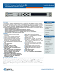
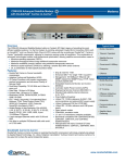
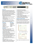
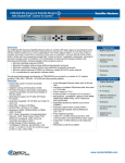
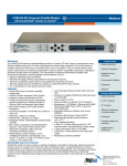
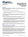
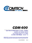
CDM-625 Advanced Satellite Modem with DoubleTalk® Carrier-in-Carrier® Overview Typical Users The CDM-625 Advanced Satellite Modem builds on Comtech EF Data’s legacy of providing the most efficient satellite modems. It is the first modem to combine advanced Forward Error Correction (FEC) such as VersaFEC and Low Density Parity Check (LDPC) codes with the revolutionary DoubleTalk Carrier-inCarrier bandwidth compression, allowing for maximum savings under all conditions. This combination of advanced technologies enables multi-dimensional optimization, allowing satellite communications users to: • Minimize operating expenses (OPEX) • Maximize throughput without using additional transponder resources • Maximize availability (margin) without using additional transponder resources • Minimize capital expenses (CAPEX) by allowing a smaller BUC/HPA and/or antenna • Or, a combination to meet specific business needs Features • DoubleTalk Carrier-in-Carrier bandwidth compression • Carrier-in-Carrier Automatic Power Control • Adaptive Coding and Modulation (ACM) • Packet Processor with header compression, payload compression, advanced Quality of Service (QoS) and Managed Switch Mode • 4-port managed Ethernet switch with VLAN and QoS • Jumbo frame support • Dual Band Capability: 70/140 MHz and L-Band in same unit, extended L-Band receive • Data Rate: 18 kbps to 25 Mbps • Symbol Rate: 18 ksps to 12.5 Msps • Modulation: BPSK, QPSK/OQPSK, 8PSK/8QAM, 16-QAM • FEC: Viterbi, Sequential, Concatenated Reed Solomon, TCM, Turbo Product Code (TPC) (IESS-315 Compliant), LDPC Code and VersaFEC (low-latency LDPC) • Widest Range of data interfaces: EIA-422/530, V.35, G.703 T1, G.703 E1, G.703 T2, G.703 E2, Quad G.703 E1, ASI, LVDS, HSSI, 4-port 10/100Base-T Ethernet Satellite Modems • IEEE 1588v2 Precision Time Protocol • Sub Mux to multiplex IP/Ethernet traffic with serial or G.703 traffic • Drop & insert for T1/E1 • Enhanced D&I++ for single T1/E1 & quad E1 • Management: 10/100Base-T Ethernet with SNMP, Distant End SNMP Proxy, HTTP, Telnet and EIA-232/EIA-485 ® • Carrier ID using MetaCarrier Technology • Embedded Distant-end Monitor and Control (EDMAC) • Automatic Uplink Power Control (AUPC) • Engineering Service Channel (ESC/ESC++) • Standard high-stability internal reference -8 (± 6 x 10 ) • 5-tap Adaptive Equalizer • L-Band TX: 10 MHz reference for BUC, FSK communications and optional BUC power supply • L-Band: Advanced FSK for LPOD M&C • L-Band RX: 10 MHz reference and LNB power supply • Open network modes • 1:1 and 1:10 redundancy switches available Doubletalk Carrier-In-Carrier DoubleTalk Carrier-in-Carrier, based on patented “Adaptive Cancellation” technology, allows transmit and receive carriers of a duplex link to share the same transponder space. DoubleTalk Carrier-in-Carrier is complementary to all advances in modem technology, including advanced FEC and modulation techniques. As these technologies approach theoretical limits of power and bandwidth efficiencies, DoubleTalk Carrier-in-Carrier utilizing advanced signal processing techniques provides a new dimension in bandwidth efficiency. • Mobile Operators • Telecom Operators • Satellite Service Providers • Government & Military • Enterprise • Offshore Common Applications • Mobile Backhaul • G.703 Trunking • IP Trunking • Offshore & Maritime Communications • Enterprise • Communications onthe-Move • Satellite News Gathering BUY NOW Figure 1 shows the typical full-duplex satellite link, where the two carriers are adjacent to each other. Figure 2 shows the typical DoubleTalk Carrier-in-Carrier operation, where the two carriers are overlapping, thus sharing the same spectrum. Figure 1 Figure 2 When observed on a spectrum analyzer, only the Composite is visible. Carrier 1 and Carrier 2 are shown in Figure 2 for reference only. As DoubleTalk Carrier-in-Carrier allows equivalent spectral efficiency using a lower order modulation and/or code rate, it can simultaneously reduce CAPEX by allowing a smaller BUC/HPA and/or antenna. Alternatively, DoubleTalk Carrier-in-Carrier can be used to achieve very high spectral efficiencies E.g., DoubleTalk Carrier-in-Carrier when used with 16-QAM approaches the bandwidth efficiency of 256-QAM (8 bps/Hz). When combined with VersaFEC or LDPC/TPC, it can provide unprecedented savings in transponder bandwidth and power utilization. This allows for its successful deployment in bandwidth-limited and power-limited scenarios, as well as reduction in earth station BUC/HPA power requirements. Carrier-in-Carrier® is a Registered Trademark of Comtech EF Data DoubleTalk® is a Registered Trademark of Raytheon Applied Signal Technology VersaFEC is a Registered Trademark of Comtech EF Data Carrier-in-Carrier Automatic Power Control (CnC-APC) The patent-pending Carrier-in-Carrier Automatic Power Control (CnC-APC) mechanism enables modems on both sides of a CnC link to automatically measure and compensate for rain loss while maintaining the Total Composite Power. In addition to automatically compensating for rain loss, CnC-APC also enables the modems to share link margin, i.e. a modem in clear sky conditions can effectively transfer excess link margin to a distant end modem experiencing fade, thereby further enhancing overall availability. VersaFEC Forward Error Correction CDM-625 is the first modem to offer VersaFEC, a patented system of high performance short-block low-latency LDPC codes designed to support latency-sensitive applications, such as cellular backhaul over satellite. VersaFEC provides excellent coding gain with lowest possible latency. VersaFEC’s Eb/No performance is similar to that of DVB-S2 (short block) or LDPC (16k block) with 70-90% lower latency. Compared to TPC, VersaFEC can provide coding gain of 1.0 dB or more. The new Ultra Low Latency (ULL) codes provide even lower latency compared to standard VersaFEC codes. Adaptive Coding & Modulation (ACM) Satellite users have traditionally relied on worst case link margin to overcome rain fade which leads to significant inefficiencies. ACM converts the fade margin into increased throughput – gain of 100% or more is possible. ACM maximizes throughput under all conditions – rain fade, inclined orbit satellite operation, antenna mis-pointing, noise, interference and other impairments. ACM can also be used with DoubleTalk Carrier-in-Carrier. Low Density Parity Check Codes (LDPC) & Turbo Product Codes (TPC) nd CDM-625 offers an integrated LDPC and 2 Generation TPC codec. LDPC is an advanced Forward Error Correction technique capable of providing performance much closer to Shannon limit. The current LDPC implementation can provide 0.7 to 1.2 dB additional coding gain compared to an equivalent TPC code. In order to take full advantage of the increased coding gain provided by LDPC, Comtech EF Data has developed a patented 8-QAM modulation that allows for acquisition and tracking at much lower Eb/No compared to 8PSK. Dual Band Capability CDM-625 supports 70/140 MHz and L-Band capability in the same unit with independently selectable transmit and receive IF. This simplifies sparing and stocking in networks requiring 70/140 MHz and L-Band units. 4-Port Managed Ethernet Switch with VLAN & QoS CDM-625 base modem incorporates a 4-port 10/100Base-T managed Ethernet switch with VLAN capability and priority-based Quality of Service. Access (Native) Mode and Trunk Mode are supported. Traffic can be prioritized using port-based priority or VLAN priority. The maximum Ethernet frame size with Rev 2 HW is 2048 bytes. Packet Processor The Packet Processor enables efficient IP networking and transport over satellite by adding routing capability with very low overhead encapsulation, header compression, payload compression and Quality of Service to the CDM-625. The advanced QoS combined with header and payload compression ensures the highest quality of service with minimal jitter and latency for real-time traffic, priority treatment of mission critical applications and maximum bandwidth efficiency. Header Compression The Packet Processor incorporates industry-leading header compression for IP traffic. Header compression can reduce the 40 byte IP/UDP/RTP header to as little as 1 byte. For TCP/IP, the 40 byte header is reduced to as little as 3 bytes. For applications such as VoIP, header compression can provide bandwidth savings exceeding 60%. E.g. the 8 kbps G.729 voice codec requires 24 kbps of IP bandwidth once encapsulated into an IP/UDP/RTP datagram. With header compression, the same voice call needs about 8.5 kbps – a saving of almost 65%. And, bandwidth requirements for typical Web/HTTP traffic can be reduced by 10% or more with TCP/IP header compression. Payload Compression The Packet Processor incorporates industry-leading payload compression for IP traffic. Implemented in the hardware for maximum throughput and efficiency, payload compression can reduce the required satellite bandwidth by as much as 40-50%. Streamline Encapsulation (SLE) The Packet Processor incorporates Comtech EF Data’s patent-pending very low overhead Streamline Encapsulation (SLE). SLE can reduce the encapsulation overhead by as much as 65% compared to industry standard HDLC. Advanced Quality of Service (QoS) The Packet Processor incorporates multi-level QoS to ensure the highest quality service with minimal jitter and latency for real-time traffic, priority treatment of mission critical applications and maximum bandwidth efficiency. Supported modes are: • DiffServ – Industry-standard method of providing QoS enabling seamless co-existence in networks that implement DiffServ • Max/Priority – Provides multi-level traffic prioritization with the ability to limit maximum traffic per priority class • Min/Max – Provides a Committed Information Rate (CIR) to each user defined class of traffic with the ability to allow a higher burstable rate depending on availability Managed Switch Mode Managed switch modem enables layer 2 operation with the Packet Processor. This provides significant bandwidth savings for layer 2 operation with very low overhead Streamline Encapsulation, header compression and payload compression. Quad E1 Interface (QDI) with Enhanced D&I++ The CDM-625 supports a Quad E1 interface that can aggregate up to four full or fractional E1s into a single carrier, with very low overhead. This provides significant CAPEX savings by reducing the number of modems and could possibly reduce the BUC/HPA size by eliminating the multi-carrier backoff. A proprietary, closed network drop & insert (D&I++) allows for dropping or inserting any combination of 1 to 31 time slots on each E1. D&I++ is supported for E1-CCS only. IP Sub Multiplexer The IP sub mux allows multiplexing IP/Ethernet traffic with serial or G.703 traffic into a single carrier. This is particularly useful for cellular backhaul when both E1 and IP backhaul is required. This reduces the number of modems and could possibly reduce the BUC/HPA size by eliminating the multi-carrier backoff. The IP sub mux ratio ranges from 9:1 (IP data rate is 9 times that of the serial or G.703 data rate) to as low as 1:59. EDMAC & AUPC The CDM-625 supports EDMAC, EDMAC-2, EDMAC-3 and AUPC. EDMAC/EDMAC-2/EDMAC-3 can be used to monitor and control the distant end of a satellite link using a proprietary overhead channel. EDMAC-3 is also used for SNMP management of the distant end modem. AUPC enables automatic uplink power control for a duplex link. Management & SNMP Proxy The modem can be managed via the front panel, the remote M&C port (EIA-232/EIA-485), or the 10/100Base-T Ethernet port. With support for SNMP, HTTP and Telnet, the modem can be easily integrated into an IP-based management system. The CDM-625 can also act as SNMP proxy for the distant end modem. This allows distant end modem management using SNMP without requiring an end-to-end IP link. IEEE 1588v2 Precision Time Protocol (PTP) PTP has emerged as the key technology for frequency, time and phase synchronization over a packet network. The CDM-625 is the first satellite modem to incorporate hardware support for PTP, thereby significantly improving synchronization accuracy for satellite backhaul. PTP requires Revision 2 modem hardware without the Packet Processor. Advanced FSK for LPOD Monitoring & Control The Advanced FSK allows for monitoring and control of LPOD through modem front panel menus, serial remote control and Telnet. Feature Enhancements Enhancing the capability of the CDM-625 in the field is easy. Features that do not require additional hardware can be added on site, using FAST access codes purchased from Comtech EF Data. Specifications Data Rate Symbol Rate Operating Frequency Major Operating Modes (See User Manual For Details) FEC Options None Viterbi: k=7, per IESS-308/309 Viterbi with Reed Solomon Sequential Reed Solomon TCM (Per IESS310) Integrated LDPC and TPC (2nd Gen) Codec (Optional Plug-in Module) 18 kbps to 25 Mbps, in 1 bps steps (modulation, FEC & data interface dependant) 18 ksps to 12.5 Msps 50 – 180 MHz (standard) and 950 – 2000 MHz (TX) & 950 – 2150 MHz (RX) (Option), (Note: extended L-Band receive supported on modems shipped since January 2013) 100 Hz resolution, independent TX and RX operation Open network, per IESS-308 / 309 / 310 / 314 transparent, closed network per IESS-315 LDPC / TPC Codec (optional plug-in module) VersaFEC Codec (optional plug-in module) with ACM or Constant Coding & Modulation (CCM) EDMAC Framed with/without AUPC RS Outer Codec High rate ESC / Enhanced ESC (ESC++) Drop & insert (D&I) /Enhanced D&I++ Quad E1 drop & insert (QDI) DoubleTalk Carrier-in-Carrier (optional plug-in module) Uncoded BPSK/QPSK/OQPSK Rate 1/2 BPSK/QPSK/OQPSK Rate 3/4 QPSK/OQPSK Rate 7/8 QPSK/OQPSK Rate 3/4 16-QAM Rate 7/8 16-QAM See CDM-625 user manual for details Open network and closed network modes 8PSK/TCM Rate 2/3 LDPC Code Rates Rate 1/2 BPSK/QPSK/OQPSK Rate 2/3 QPSK/OQPSK/8PSK/8-QAM Rate 3/4 QPSK/OQPSK/8PSK/8-QAM/16-QAM TPC Code Rates Rate 5/16 BPSK Rate 21/44 BPSK/QPSK/OQPSK Rate 3/4 QPSK/OQPSK/8PSK/8-QAM/16-QAM Rate 7/8 QPSK/OQPSK/8PSK/8-QAM/16-QAM Rate 0.95 QPSK/OQPSK/8PSK/8-QAM VersaFEC Codec BPSK Rate 0.488 (Optional Plug-in QPSK Rate 0.533, 0.631, 0.706, 0.803 Module) 8-QAM Rate 0.576 (ECCM), 0.642, 0.711, 0.780 16-QAM Rate 0.644 (ECCM), 0.731, 0.780, 0.829, 0.853 BPSK 0.493 (ULL) QPSK 0.493, 0.654, 0.734 (ULL) Scrambling IDR Mode, no RS, - per ITU V.35 (Intelsat variant) IBS mode, no RS - per IESS-309, externally frame synchronized Transparent Closed Network mode, no RS or Turbo coding - per ITU V.35 (Intelsat variant) EDMAC mode, no RS coding - externally frame synchronized - proprietary Turbo Product Code/LDPC/VersaFEC modes externally frame synchronized - proprietary All RS modes - externally frame synchronized per IESS-308/309/310 Management 10/100Base-T Ethernet with SNMP, HTTP and Telnet support, EIA-232, EIA-485 (2- or 4-wire) Form C Relays Hardware fault, RX and TX traffic alarms, open network backward alarms External BNC connector Reference Input: 1, 2, 5, or 10 MHz, -6 dBm to (Input OR Output) +10 dBm, 50 Ω/75 Ω (nominal) Output: 10 MHz, 2.7 V peak-to-peak ± 0.4 V, low impedance output Data Interfaces EIA-422/-530 DCE , Up to 14 Mbps 25-pin D-sub (female) V.35 DCE , Up to 14 Mbps LVDS Serial , Up to 25 Mbps 25-pin D-sub (female) HSSI Serial , Up to 25 Mbps G.703 T1, 1.544 Mbps (Balanced 100 Ω) G.703 T2, 6.312 Mbps (Unbalanced 75 Ω or balanced 110 Ω) G.703 E1, 2.048 Mbps (Unbalanced 75 Ω or balanced 120 Ω) G.703 E2, 8.448 Mbps (Unbalanced 75 Ω) ASI , Up to 25 Mbps Additional 2.048 Mbps E1 Ports for Quad-E1 (Balanced 120 Ω) Overhead Data Modem Alarms 4-port 10/100Base-T Managed Ethernet Switch (Optional Packet Processor Available) Modulator Frequency Stability Transmit Filtering Transmit Filter Rolloff Harmonics and Spurious Transmit On/Off Ratio Output Phase Noise Output Power Power Accuracy Output Impedance & Return Loss Clocking Options External TX Carrier Off BUC Reference (10 MHz) BUC Power Supply (HW Option) 9-pin D-sub (female) or BNC (female) BNC (female) 9-pin D-sub (female) 44-pin High-density D-sub (male) 15-pin D-sub (male) 4 x RJ-45 ± 0.06 ppm (± 6 x 10⁻⁸), 0° to 50°C (32° to 122°F) with internal reference Per IESS-308 25%, 35% Better than -60 dBc/4 kHz (typically <-65 dBc/4kHz) Measured from 1 to 500 MHz (50-180 MHz band) Measured F0 ± 500 MHz (950-2000 MHz band) -60 dBc minimum < 0.480° rms double sided, 100 Hz to 1 MHz (Minimum 16 dB better overall than the Intelsat IESS-308/309 requirements) dB/Hz Frequency Offset -63.0 100 Hz -73.0 1 kHz -83.0 10 kHz -93.0 100 kHz Fundamental AC line spurious is -42 dBc or lower The sum of all other single sideband spurious, from 0 to 0.75 x symbol rate, is -48 dBc or lower 50-180 MHz: 0 to -25 dBm, 0.1 dB steps 950-2000 MHz: 0 to -40 dBm, 0.1 dB steps 50-180 MHz: ± 0.5 dB over frequency, data rate, modulation type and temperature range of 15 to 35° C ± 0.8 dB over frequency, data rate, modulation type and temperature range of 0 to 50° C 950-2000 MHz: ± 0.7 dB over frequency, data rate, modulation type and temperature range of 15 to 35° C ± 1.0 dB over frequency, data rate, modulation type and temperature range of 0 to 50° C 50-180 MHz: 50 Ω/75 Ω, 16 dB minimum return loss (18 dB typical), BNC connector 950-2000 MHz: 50 Ω, 19 dB minimum return loss (21 dB typical), Type-N connector Internal, ± 0.06 ppm (SCT) External, locking over a ± 100 ppm range (TT) Loop timing (RX satellite clock) – supports asymmetric operation External clock By TTL ‘low’ signal or external contact closure Via TX IF center conductor, 10.0 MHz ± 0.06 ppm (with internal reference), selectable on/off, 0.0 dBm ± 3 dB 24 VDC, 4.17 Amps max., 90 W @ 50° C 48 VDC, 3.125 Amps max., 150 W @ 50° C (180 W @ 30° C) Supplied through TX IF center conductor and selectable on/off via M&C control Demodulator Input Power Range, Desired Carrier Max Composite Operating Level Absolute Maximum Adaptive Equalizer Acquisition Range Below 64 ksymbols/sec Between 64 and 389 ksymbols/sec Above 389 ksymbols/sec Acquisition Time Plesiochronous/ Doppler Buffer Receive Clock Clock Tracking LNB Reference (10 MHz) LNB Voltage Monitor Functions 48 VDC primary power supply Hardware 50-180 MHz: -105 + 10 log (symbol rate) to -70 + 10 log (symbol rate) dBm 950-2150 MHz: -130 + 10 log (symbol rate) to -80 + 10 log (symbol rate) dBm 50-180 MHz: 94 – 10 log (symbol rate, desired carrier) dBc, +10 dBm max., with the additional requirement that within ± 10 MHz of the desired carrier the composite power is ≤ +30 dBc 950-2150 MHz: 102 – 10 log (symbol rate, desired carrier) dBc, +10 dBm max., with the additional requirement that within ± 10 MHz of the desired carrier the composite power is ≤ +30 dBc +20 dBm 5-tap design, selectable on/off Programmable in 1kHz increments ± 1 kHz to ± (Rs/2) kHz, where Rs = symbol rate in ksymbols/sec ± 1 kHz to ± 32 kHz ± 1 kHz to ± (0.1 * Rs) kHz, up to a maximum of ± 200 kHz Highly dependent on data rate, FEC rate, and demodulator acquisition range. E.g.: 120 ms average at 64 kbps, R1/2 QPSK, ± 10 kHz acquisition sweep range, 6 dB Eb/No Selectable from 64 to 262,144 bits, in 16-bit steps (Additional limitations for G.704 frame boundaries) RX satellite, TX terrestrial, external reference ± 100 ppm minimum Via RX IF center conductor, 10.0 MHz ± 0.06 ppm (with internal reference), selectable on/off, -3.0 dBm ± 3 dB Selectable on/off, 13 VDC, 18 VDC per DiSEq 4.2 and 24 VDC at 500 mA maximum Eb/N0 estimate, corrected BER, frequency offset, buffer fill state, receive signal level DoubleTalk Carrier-in-Carrier Delay Range 0 to 330 ms Power Spectral Density BSPK/QPSK/8PSK/8-QAM: –7 dB to Ratio +11 dB (Interferer to Desired) 16-QAM: -7 dB to +7 dB Maximum Symbol Rate 3:1 (TX:RX or RX:TX) Ratio Eb/No Degradation 0 dB Power Spectral Density Ratio BPSK/QPSK/OQPSK: 0.3 dB 8-QAM: 0.4 dB 8PSK: 0.5 dB 16-QAM: 0.6 dB +10 dB power spectral density ratio Additional 0.3 dB Satellite Restrictions Satellite in “loop-back” mode (i.e., the transmit station can receive itself) “Non-processing” satellite (i.e., does not demodulate or remodulate the signal) Available Options Hardware 100 – 240 VAC, 175 W AC primary power supply Hardware -48 VDC, 125 W primary power supply Hardware -24 VDC, 120 W primary power supply Hardware 24 VDC, 90 W @ 50°C BUC power supply, AC, 24 VDC or Hardware Hardware Hardware Hardware FAST FAST FAST FAST FAST FAST FAST FAST FAST FAST FAST FAST FAST FAST FAST FAST 48 VDC, 150 W @ 50°C (180 W @ 30°C) BUC power supply, AC or 48 VDC primary power supply Integrated TPC (2nd generation) and LDPC Codec module DoubleTalk Carrier-in-Carrier module VersaFEC Codec module Packet Processor L-Band IF (in addition to 70/140 MHz) Modem data rate – 10 Mbps, 15 Mbps, 20 Mbps or 25 Mbps 8PSK and 8-QAM modulation (8-QAM requires TPC/LDPC or VersaFEC Codec) 16-QAM modulation TPC/LDPC Codec data rate – 10 Mbps, 15 Mbps, 20 Mbps or 25 Mbps DoubleTalk Carrier-in-Carrier (full) – 512 kbps, 1.1 Mbps, 2.5 Mbps, 5 Mbps, 10 Mbps, 15 Mbps, 20 Mbps or 25 Mbps DoubleTalk Carrier-in-Carrier (fractional) – 2.5 Mbps, 5 Mbps, 10 Mbps, 15 Mbps, 20 Mbps or 25 Mbps VersaFEC Codec data rate (CCM) – 2.5 Mbps, 5 Mbps or 16 Mbps VersaFEC Codec symbol rate (ACM) – 300 ksps, 1.2 Msps or 4.1 Msps Open network – IBS with high rate IBS ESC, IDR and audio D&I / D&I++ for single Port T1/E1 D&I++ For Quad E1 Port 2, 3 and 4 Quality of Service (requires Packet Processor) Header Compression (requires Packet Processor) Payload Compression (requires Packet processor) Advanced Network Timing (IEEE 1588v2 PTP) Accessories CRS-170A CRS-180 CRS-300 CRS-280 CRS-280L CRS-500 CRS-282XXX 1:1 Modem Redundancy Switch (L-Band) 1:1 Modem Redundancy Switch (70/140 MHz) 1:10 Modem Redundancy Switch (Not available with Packet Processor) 1:10 IF Redundancy Switch (70/140 MHz) 1:10 IF Redundancy Switch (L-Band) 1:N Modem Redundancy System (For use with Packet Processor Only) 1:10 IF Redundancy Switch (For use with CRS-500) Environmental And Physical Temperature Operating: 0 to 50°C (32 to 122°F) Storage: -25 to 85°C (-13 to 185°F) Power Supply 100 – 240 VAC, +6%/-10%, 50/60 Hz, auto sensing -24 VDC (HW option) -48 VDC (HW option) Power 48 W (typical with TPC/LDPC Codec and Carrier-inConsumption Carrier module installed), 55 W (max.) 60 W (typical with TPC/LDPC Codec, Packet Processor and Carrier-in-Carrier module installed), 67 W max. 280 W (typical with TPC/LDPC Codec, Carrier-inCarrier module and 48 VDC BUC power supply installed), 300 W (max.) Dimensions (1RU) 1.75” x 19.0” x 17.65” (height x width x (4.4 x 48 x 44.8 cm) approximate depth) Weight 10.8 lbs (4.9 kg) maximum, with all option modules and 48 VDC BUC power supply installed CE Mark EN 301 489-1 (ERM) EN55022 (Emissions) EN55024 (Immunity) EN 61000‐3‐2 EN 61000‐3‐3 EN60950 (Safety) FCC FCC Part 15, Subpart B See all of Comtech EF Data’s Patents and Patents Pending at http://patents.comtechefdata.com Comtech EF Data reserves the right to change specifications of products described in this document at any time without notice and without obligation to notify any person of such changes. Information in this document may differ from that published in other Comtech EF Data documents. Refer to the website or contact Customer Service for the latest released product information. © 2013 Comtech EF Data ds-cdm625.docx 3/14/2013