1
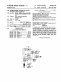
I
Umted States Patent [19]
[11] Patent Number:
Duffield et al.
[45]
[54]
I
TUNER CONTROL APPARATUS HAVING
Date of Patent:
4,751,578
OTHER PUBLICATIONS
my“: lnglfmlzpoblgséhalgy
Im'i
'
"'5' ""
m ‘° '
Mark Fleischmann, “Bold New Gear”, Video Maga
°
zine, Apr. 1989, pp. 36-39 and 54-55.
'
[73] Assignee:
Grundig Service Manual, CUC 2400.
RCA Licensing Corporation,
Hitachi VT-S625 User Manual, pp. 18-19.
PrinCctOn, N-J-
RCA VPT 595 Videocassette Recorder Owner’s Man
[21] Appl. No.: 334,068
_
[22] Filed:
Apr. 6, 1989
[51]
“*1, PP- _29-3°__
RCA Dimensla Interconnect and Operations Manual, p.
1Q
Int. (31.5 ...................... .. HMN 5/50; H04N 5/44;
pn'mary Examiner_john K_ Peng
H04N 9/74
[52]
Sep. 25, 1990
6/1988 Reiter .......................... ...... .. 358/22
I UNE'BY'LABEL CAPABH‘H Y
[75] Inventors:
4,959,720
Attorney, Agent, or Firm-Joseph S. Tripoli; Peter M.
US. Cl. ................................. .. SSS/191.1; 358/22;
Emanuel; Thomas F_ Lenihan
358/ 194. l; 340/ 825.03; 455/186; 455/603
[58]
Field of Search .................. .. 358/22, 191.1, 194.1;
[56]
[57]
ABSTRABT
340/325-03, 825-29; 455/151, 136, 603
A tuning system is provided which allows a user to
. References Cited
enter text labels associated with respective channels or
television programs to be tuned so that, thereafter, a
channel or program to be tuned may be selected by the
U'S' PATENT DOCUMENTS
4,123,713 10/1978
Wine . . . . . .
. . . .. 325/455
user by entering its label. Scheduling of television pro
4’181469
Tanflka ~ - - - ~ ' -
~ - ~ -- 455/136
grams by label is also provided by storing time-related
2/1930
Riggs a1’
data as well as channel~related data and associating
4:356:509 10/1982 Sker103 et ah _
N 358/19“
these data for each television program w1th a user
4,456,925
.. ass/194.1
entered label
6/1984 Skerlos etal. .
4,644,349 2/ 1987 Fujita et a1.
. 340/825.25
4,706,121 11/1987 Young ............................... .. 358/ 142
8
8 Drawing Sheets
1M I 7
“mums
'
102
w
my
——>
mu
'
111
to!
roam
mm /’°°
NO
1?‘
‘"0
mm
"mm
m
c
‘
MRS".-
1/22
mm "128;"
‘110
m
on In:
mm!
min
124
/112
US. Patent
Sep.25, 1990
'
Sheet 1 of 8
4,959,720
100
TUNING VOLTAGE
1 02
TUNER
ASSEMBLY
111
lF AMPLIFIER
104
BAND
I
109
AND
DETECTOR
TELEVISION
TUNER
CONTROLLER
VIDEO SIGNAL
1 18
PROCESSOR
DATA
KEYBOARD
}
SYSTEM
‘
CONTROL
p0
ON SCREEN
DISPLAY
CIRCUIT
IR RECEIVER
116
124
M
112
an
55
an
TIMER /
128
DE
120
FIG. 1
T0 DISPLAY
SCREEN
DRIVERS
US. Patent
Sep.25‘, 1990
Sheet 3 of 8
4,959,720
12:00 AM STEREO 13
WTHR
SLEEP 1:00 AL ANT B
CHANNEL MEMORY 13
WTHR
ENTER STATION ID: 13
—TH R
‘TEXT ON’ TO SET ID
xx CHANNEL ID‘S LEFT
PUSH ENTER TO STORE
PUSH — TO ERASE
‘FIG. 3d
ENTER STATION : -
PUSH ENTER TO SEARCH
FIG. I 3e
US. Patent
Sep.'25, 1990
Sheet 4 of 8
m '4°°
4,959,720
FIG. 4
410
DISPLAY LABEL
IR cone,
YES
IN STORE
‘TEXT ON ' ?
YES
PROGRAMMING
CHANNEL MODE?
TEXT ENTRY
sCREEN
405
NO
DISPLAY
'
TUNE-BY-LABEL
J
TEXT ENTRY sCREEN
425
4(35
IS IR CODE A TEXT
YES
N0
IN TEXT
CHARACTER?
DIsPLAY ERRoR
y
MESSAGE
ENTRY MODE?
43o
YES
APPEND NEW
~44‘)
CHARACTER TO LABEL
No
445
J
BEING ENTERED
'TEiiTaEigge?' ?
GO TO
~450
NONALPHANUMERIC
J
DECODING ROUTINES
YEs
455
480
No
‘
DISPLAY
ERROR
DISPLAYED?
V
4
—n
MESSAGE
YES
460
No
'5 LABEL '
"WY?
485
YES
490
DoEs THIs CHANNEL
ALREADY HAvE A
YES
LABEL ?
12%;
MESSAGE
LABEL
TUNE
CHANNEL
HAvING THIS
470
NO
I
sToRE
LABEL
465
ERASE
OLD
495
NEW
LABEL
498
US. Patent
Sep.25, 1990
Sheet 6 of8
4,959,720
600
FIG. 6
UL = HIGHEST
LABEL NUMBER
610
LL = 1
615
\_.__
MOVE ALL LABELS AT
OR ABOVE CURRENT
POSITION UP 1 POSITION
620
CURRENT CENTER LABEL
625
READ CURRENT CENTER
LABEL INTO A
630
CURRENT
CENTER
A<B
CURRENT
CENTER
1ST CHAR?
VALUE + 1
VALUE - 1
635
660
B
2ND CHAR?
640
B ‘
3RD CHAR?
645
A<B
4TH CHAR?
A
'
B
US. Patent
Sep.25, 1990
Sheet 7 018
4,959,720
700
'
UL = HIGHEST
LABEL NUMBER
71 0
LL = 1
71 5
GET
‘LABEL NOT FOUND“
W HULL )_
720
MESSAGE
"'2'" '
CURRENT CENTER LABEL
READ CURRENT CENTER
725
LABEL INTO A
760
730
‘
LL =
CURRENT
:
A<B
1ST CHAR,
CENTER
'
vALuE + 1
A>5
CURRENT
CENTER
vALuE - 1
735
B
2ND CHAR?
740
B
3RD CHAR?
745
A<B
4TH CHA Fl?
750
US. Patent
Sep.25, 1990
FIG. 83
TO SELECT MODE
PUSH NUMBER SHOWN
1 CLOCK SET
2 NORMAL PROGRAM
3 DAILY PROGRAM
4 WEEKLY PROGRAM
' s LABEL PROGRAM
6 PROGRAM REv|Ew
TO END PUSH PROGRAM
FIG. 80
TO SELECT MODE
PUSH NUMBER SHOWN
“100K SET
2 NORMAL PROGRAM
3 DAILY PROGRAM
4 WEEKLY PROGRAM
5 LABEL PROGRAM
s VACATION PROGRAM
1 PROGRAM REvlEw
TO END PUSH PROGRAM
Sheet 8 On;
‘ 4,959,720
FIG. 8b
LABEL PROGRAM
PROGRAM 1
CH 0 4
TIME ON 0 6:0 0 PM
TIME OFF 0 s :o 5 PM
sTART DAY
SUN
LABEL
LA
TO END PUSH PROGRAM
FIG. 8d
“(mg PROGLQAM
LABEL 2
LABEL 3
LABEL 4
LABEL
LABEL 5
6
cc
Cos
NY
We
COL
TO END PUSH PROGRAM
4,959,720
1
2
channel in response to the selection of a network’s
TUNER CONTROL APPARATUS HAVING
TUNE-BY-LABEL CAPABILITY
name.
Efforts have been made by manufacturers to relate
channel numbers to network names. For example, it is
known from GRUNDIG television receiver CUC-24-00
to display on the television screen a station identi?ca
FIELD OF THE INVENTION
This invention relates to the ?eld of tuner controls for
tion label (previously entered by the user) whenever a
television receivers (including VCRs) and radios.
channel is selected. However, the user must still some
CROSS REFERENCE TO RELATED
APPLICATIONS
.
how remember which channel is assigned to which
10
network, because channel selection in this system is by
This application is related to an application entitled
TUNER CONTROL APPARATUS HAVING
TUNE-BY-LABEL CAPABILITY AND USING
ALPHABETICAL LABEL STORAGE, ?led in the
name of David Jay Duf?eld and assigned to the same
channel number.
Thus, it is desirable that television manufacturers
provide remote control handunits which allow viewers
to select the channels by name.
A tune-by-label system is known from US. Pat. No.
assignee as the subject application.
4,706,121 (Young). However, Young provides no
means by which the user can enter labels of his own
BACKGROUND OF THE INVENTION
In the United States there are at least 3 major broad
casting networks (e.g. ABC, NBC, and CBS), and also
20
a number of cable service networks (e.g. HBO, ESPN,
choosing, either for display or for selecting a channel.
In Young, the labels are provided by a broadcaster, as
part of a TV schedule transmitted to an in-home tuner
controller. The labels, such as HBO and ESPN, are
displayed in a menu for selection by the user. Such a
Cinemax, etc.), ‘each of which distributes broadcast
television programs throughout the country. Many
system requires costly and complex circuity. Perhaps,
viewers tend to associate their favorite television pro
more importantly, it requires the cooperation of broad
grams with the networks that carry them. A common 25 casters to dedicate limited spectrum space to the trans
problem is that there are so many channels available
mission of schedule information.
that it is difficult for a viewer to remember which chan
nel number corresponds to which network. For exam
SUMMARY OF THE INVENTION
ple, in some areas of the country a viewer has access to
According to the present invention, a tuning system is
as many as 40 channels. Thus, tuning by channel num
provided which allows a user to enter a text label and
ber, although widely used, may not be desirable in these
associate it with a particular channel to be tuned. There
after, a channel to be tuned may be selected by the user
situations.
Furthermore, in the hotel/motel environment, the
by entering its label.
visitor is typically unfamiliar with local channel num
In another embodiment of the invention, a tuner con
bers. When the visitor wishes to watch a favorite pro 35
troller
includes a scheduler which allows a user to enter
gram on a known major network, he may have dif?
a text label, such as the abbreviation for the name of a
television ' program, to be associated with previously
' culty locating the proper local channel owned by, or
affiliated with the major network. Compounding this
entered programming information. Thereafter, each
problem is the fact that it is common practice among
cable companies in the United States to remodulate
broadcast signals to di?'erent channels of the RF spec
trum than those channels which they normally occupy.
Unfortunately, this also has the effect of confusing the
viewer because, for instance, UHF channel 29 may be
remodulated (down converted) to occupy the fre
quency space of, for example, VHF channel 9. Thus,
even if a viewer happened to know that the FOX
Broadcasting Network corresponds to channel 29 (as it
does in Philadelphia), the viewer may still have diffi
culty locating his desired programs when the signals
transmitted by channel 29 are in fact received on cable
channel 9.
A common solution to this problem is to distribute
channel conversion charts to cable subscribers so that
time the text label is entered, the television program will
be automatically scheduled for future recording (in the
case of a VCR), or viewing (in the case of a television
set).
45
BRIEF DESCRIPTION OF THE DRAWING
FIG. 1 is a block diagram of the tuning portion of a
television receiver suitable for implementing the inven
tion.
FIG. 2 is an illustration of the keyboard of a remote
control handunit suitable for implementing the inven
tion.
FIGS. 3a-3e are illustrations of display screens gener
ated by the circuitry of FIG. 1.
FIG. 4 is a ?owchart of a program for use with the
they may locate the proper cable channel, given the 55 circuitry of FIG. I, for implementing the invention.
FIGS. 54 and 5b illustrates a memory arrangement
standard broadcast channel, from a printed television
produced by implementation of the ?owchart of FIG.
schedule. This solution is less than satisfactory because
4.
of the relatively large number of available channels.
FIG. 6 illustrates in detail a portion of the flowchart
Additionally, a problem arises because the channel
numbers assigned to the major networks are not the
same across the country. For example, the National
Broadcasting Company (NBC) broadcasts on channel 4
in New York City, N.Y., on channel 3 in Philadelphia,
Pa., on channel 5 in Cincinnati, Ohio, and on channel 11
of FIG. 4.
FIG. 7 illustrates in detail another portion of the
?owchart of FIG. 4.
FIGS. 8a-8d are illustrations of display screens gen
erated by the circuitry of FIG. 1.
in Dayton, Ohio. Because television manufacturers can
not know in advance in which viewing areas their re
ceivers will be operated, it is not possible to preprogram
DETAILED DESCRIPTION OF THE DRAWING
the tuning system at the factory to select a particular
antenna 100 which receives radio frequency (RF) sig
Referring to FIG. 1, a television receiver includes an
3
4,959,720
nals and applies them to a tuner assembly 102. Tuner
assembly 102 selects and ampli?es a particular RF sig
nal under control of a tuner controller 104 which pro~
vides bandswitching signals and tuning voltage signals
4
Operation of the apparatus illustrated in FIGS. 1, and
2, and the display screens illustrated in FIGS. 3a-3e will
now be described with reference to FIG. 4. The subject
invention makes use of the text programming capabili
to tuner assembly 102.
ties already present in, for example, the RCA CTC-l40
Tuner assembly 102 converts the received RF signal
television receiver referred to above. FIG. 3a illustrates
to an intermediate frequency (IF) signal and provides an
a STATUS display screen which is displayed by the
IF output signal to IF ampli?er and detector 108. IF
CTC-l40 television receiver in response to IR signal
ampli?er and detector 108 ampli?es the IF signal ap
transmitted when a user presses a STATUS key, such as
plied to its input terminal and detects the video informa 10 STATUS key 210 of remote control keyboard 200. The
tion contained therein. This detected video information
STATUS display provides information as to time-of
is applied as one input to a video signal switch 109, the
other input of which is coupled to a baseband video
input terminal 111 to which an external source of video
such as a VCR may be connected. Video signal switch
109 has a control input C for receiving a switching
day, station tuned, whether or not a “sleep feature” has
been enabled, and which of two antenna connectors
(ANT B) have been selected for coupling RF signals to
the tuner. FIG. 3b illustrates a STATUS display screen
modi?ed in accordance with the present invention to
display a label (in this case the station call letters
control signal. The output terminal of video switch 109
is coupled to one in-put of a video signal processor unit
WTHN) immediately below the channel number. The
122, the other input of which is connected to an on
label (WTHN) associated with the channel number (13)
screen display circuit 124. IF ampli?er and detector 108 20 _ is entered (“keyed-in”) by a user as will be described
also detects an audio signal for processing in an audio
below. Of course, the label does not have to represent
channel (not shown)._
the station call letters but rather could be any alphanu
Tuner controller 104 generates the before-mentioned
meric label comprising any of one to four characters
tuning voltage signals and bandswitching signals in
response to control signals applied from a system con 25
trol microcomputer (uC) 110. Microcomputer 110 also
generates the switching control signal for video signal
representing letters, numbers, or punctuation marks.
Thus, a user can enter any convenient label which
would aid him or her in selecting a desired channel.
The CHANNEL MEMORY display of FIG. 30 is
used for entering channel numbers and associated labels
puter 110 receives user-initiated commands from an 30 into memory. The CHANNEL MEMORY SCREEN
(FIG. 3c) is displayed in response to the activation of
infrared (IR) receiver 116 and from a keyboard 118
MENU
SETUP key 212 of remote control unit key
mounted on the television receiver itself. Microcom
switch 109. The terms “microcomputer” and “micro
processor” as used herein are equivalent. Microcom
board 200. In the illustration of FIG. 3c channel 13 has
already had a label WTHR stored for display. The
(RAM) 120 for storing channel-related data and sched 35 legend ‘TEXT ON’ TO SET ID at the bottom of the
display is an instruction to the user that, if he desires, he
uler information, such as, times and channels for future
may press TEXT ON key 206 of remote control unit
television programs. RAM 120 may be of either the
keyboard 200 to enter a text entry mode for adding a
volatile or non-volatile type. One skilled in the art will
label to the CHANNEL MEMORY display for a par
recognize that if volatile memory is utilized that it may
be desirable to use a suitable form of standby power to 40 ticular channel, or for changing a label previously en
tered. Pressing TEXT ON key 206 causes the genera
preserve its contents when the receiver is turned off.
tion of the display of FIG. 3d.
The television receiver described thusfar is known, for
The dash (—-) in the ?rst character position of the
example, from the RCA CTC~140 color television re
label in FIG. 3d is a prompt character which serves as
ceiver chassis manufactured by Thomson Consumer
Electronics, Inc., Indianapolis, Ind. The subject inven 45 a cursor to indicate the label position that will be ?lled
by the next character to be entered. The display of the
tion will now be described in detail.
,
dash may also alternate with a character from a previ
IR receiver 116 receives IR signals transmitted by,
ously entered label v(in this case W) to draw even more
for example, a remote control handunit 128 having a
attention to the character position to be ?lled. The
keyboard such as the one shown in FIG. 2 designated
puter 110 includes a timer 112, a program memory
(ROM) (not shown) and a random access memory
200. Keyboard 200 may include keys 202 for entering 50 legend “xx CHANNEL ID’S LEFT” of FIG. 3d,
where xx is actually a number, indicates to the user the
the digits 0-9, keys 203 for entering channel up and
amount of space remaining in label memory.
channel down commands and a key 204 for turning the
The relevant portion of the keycode decoding routine
receiver on and off. Remote control keyboard 200 may
for microcomputer 110 is illustrated in FIG. 4, and is
also include a section labelled TEXT having a key 206
(labelled ON) and a key 208 (labelled ENTER), the 55 entered at step 400 from other portions of the keycode
decoding routine. The received keycode is examined to
operation of which will be described below. Each of the
see if it is the TEXT ON code sent in response to the
keys in the top three rows, and ?ve keys of the fourth
pressing of key 206 of remote control keyboard 200
row have a subscript indicating a second function for its
(step 405). If so, a check is made (step 410) as to whether
respective key. Pressing TEXT ON key 206 enables
channel information is currently being stored in mem
these keys to be used for entering characters of the
ory 120 (Le. is a CHANNEL MEMORY screen being
alphabet, punctuation marks, a space character, and a
displayed?). If channel numbers are currently being
backspace command. The ?rst function of each of these
stored, the program causes the display of a label pro
keys (TRK-, TRK+, etc.) which is not directly rele
gramming text entry screen (step 415) as illustrated in
vant to the subject invention, will not be discussed.
Remote control handunit 128 includes therein elec 65 FIG. 3d.
If, however, a label is not in the process of being
tronic circuitry (not shown) for encoding a signal to be
transmitted in accordance with the particular keys
stored, it is assumed that the text is being entered for the
pressed.
purpose of tuning a new channel, and a tune-by-label
5
4,959,720
text entry screen is displayed (step 420) on the display
6
Viewers have become accustomed to tuning systems
which operate relatively quickly with little, or no dis
screen as illustrated in FIG. 3e. and the routine exited.
The next keycode received should be a text character
which therefore will cause the program to take the NO
cernible difference in speed of tuning between different
channel numbers. Therefore, it is desirable to minimize
the time required to locate a label in memory, so that the
path from decision diamond 405 to decision diamond
425 wherein a check is made to see if the received key
code is a text character. If the keycode does correspond
overall tuning time is not unnecessarily increased. This
to a text character, a decision is made as to whether the
becomes more important as the number of stored labels
increases.
program is in a text entry mode (step 430). If not, an
error message is displayed. on the display screen (step
435) and the program is exited normally. If the program
is in a text entry mode (step 430), the new character is
associated with desired channels occurs relatively infre
quently, while a search incident to a channel change
occurs with much greater frequency. In view of the
appended to the current label being keyed in (step 440)
above, it is herein recognized that it is acceptable to
It is herein recognized that the programming of labels
(or becomes the ?rst character of a new label).
decrease speed of programming in order to increase
If, on the other hand, the received keycode did not 15 label search speed during a channel change.
correspond to a text character (step 425), then the NO
Accordingly, as shown in FIGS. 5a and 5b, the pro
path will be followed to decision diamond 445. In deci
gram portion for the entry of labels produces a memory
sion diamond 445, it is determined if the keycode corre
arrangement wherein labels are arranged alphabeti
sponds to the TEXT ENTER key 208. If not, the cur
cally, and wherein each label is right-justified to facili
rent routine is exited by way of the decoding routines 20 tate retrieval searches for channel selection. It is noted
for non-alphabetical keycodes (step 450). If the TEXT
that a three character label, for example, ABC may be
ENTER key is decoded (step 445), then a check is made
entered by a user as “13450 0""ABC13". Both ofthe above labels
to see if the TUNE-BY-LABEL screen is displayed
(step 455). If so, the program recognizes that the user
has ?nished entering the label, and it begins a search to 25
see if that label exists in memory 120 (step 460). If the
label does not exist in memory 120, a “LABEL NOT
will 1" "illll'jlml?fd and "and 1" “13ABC'. This prevents user confusion
as to the location of the space character, and additionally serves to physically
locate the displayed label more toward the right-hand area of the display
screen, so as to lessen interference with the picture being displayed. The
- labels may be from one to four characters in length. Four character labels
FOUND” error message is displayed (step 465). If the
are stored in higher memory (i.e. fartherfrom the start of memory) than are
label is found in step 460, then the channel correspond
three character labels, and so on. Referring to FIG. 5a, thirteen labels
30 and their associated channel numbers are stored in al
ing to this label is tuned (step 470).
Returning to step 455, if the TUNE-BY-LABEL - phabetical order in a memory 500 in locations 501-513
screen (FIG. 3d) is not currently being displayed, then
respectively. A three character label recently entered, is
a check is made (step 475) to see if the LABEL PRO
shown stored in a “holding” memory location 520 in
GRAMMING screen is displayed (FIG. 3c). If not, I preparation for storage. In FIG. 5b newly-entered label
then a suitable error message is displayed (step 480). If, 35 KYW has been properly stored in memory location 510.
however, the LABEL PROGRAMMING screen were
displayed (step 475), then a check is made to see if the
current channel being labelled already has a label asso
ciated with it (step 485). If so, the old label is erased
(step 490), the new label stored (step 495), and_ the rou
. tine is exited (step 49B). If the channel had no label (step
485), then the program advances directly to step 495 for
storing the new label.
In a tune-by-label tuning system such as the one de
scribed above, a search of memory for a match with a 45
particular label is an additional step, not required in a
“tune by channel number” system, which will increase
the overall tuning time when changing channels. That
is, in order to ensure that a keyed-in label matches a
stored label, a four character comparison between the
two must be made. Thereafter, the label must be con
verted to data either representing the channel number,
the oscillator frequency or the magnitude of the tuning
voltage.
‘
Note that the leading space is also an ASCII text char
acter (20 Hexadecimal (HEX), or 32 decimal), and so
exhibits a value which can be used for comparison.
Therefore, while a viewer may consider KYW to be a
three character label, in fact, the program treats it as a
four character label, by evaluating and comparing the
ASCII value of the leading space.
The search is performed much more quickly when
the labels are stored in alphabetical order than when
randomly stored, because once the labels have been
arranged in an order, a binary search can be performed.
The term “binary search” as used herein means a search
in which the label memory area is divided into two
parts, one part being rejected on the basis of a compari
son with the label being searched. This process is re
peated on the accepted part of label memory until the
desired label is found. A binary search will be explained
by example with respect to FIGS. 5a and 5b. below.
As noted above, the short search duration described
It is recognized herein that the user-entered label data 55 above comes at the expense of a longer time being re
may be stored randomly, for example, in the sequence in
quired for storage. Referring again to FIGS. 5a and 5b,
which it is entered, or ordered and stored in some logi
and to the ?owchart of FIG. 6, note that each of the
cal sequence. If the data were to be stored randomly in
labels stored in locations 510-513 of FIG. 50 has been
the label memory area, and if the searches were to begin
read and rewritten to locations 511-514, respectively, in
at the start of the label memory area and progress from
order to create room to store the new label in location
label-to-label, then the duration of the search will vary
510. The ?owchart of FIG. 6 illustrates in detail pro
undesirably with the position of a particular label in the
gram block 495 (STORE NEW LABEL) of the ?ow
memory. That is, if the label searched for is found in the
chart of FIG. 4. This portion of the program is entered
?rst location examined, then the search is terminated in
at step 600. Comparison location B holds the received
the shortest possible time. On the other hand, if the label 65 keycode and corresponds to holding location 520 of
searched for is found in the last of the label storage
FIG. 5a. Microcomputer 110 keeps a record of the
locations, then the search will be terminated in the lon
number of labels entered by a user. In step 610, the
gest possible time.
maximum necessary range of LABEL memory to be
4,959,720
.
7
searched is de?ned by storing the number of labels
entered (i.e. the highest location that need be examined)
in a memory location designated UL (upper limit), and
storing the number 1 (i.e. the lowest label memory loca
tion) in a memory location designated LL (lower limit).
8
FIG. 7 illustrates in detail the contents of decision
diamond 460 of FIG. 4. This portion of the control
program is the binary search algorithm used during the
tune-by-label process. Steps 700-760 perform in the
same manner as similarly numbered steps in FIG. 6, and
If UL is not equal to LL (step 615), then the search has _ their function will not be described again. There are
two exits from this routine, 750 which corresponds to
not yet converged, and the NO path is taken to step 620,
the YES path of decision diamond 460 (i.e. a matching
wherein the current center position of label memory
500 is determined by taking the integer portion of the
average of the upper and lower limits (i.e. the integer
portion of (UL-l-LL)/2). The current center label in
memory is read into a location A (step 625), the con
tents of which will be compared to the contents of
holding location B on a character-by-character basis in
steps 630-645. In each of steps 630-645, if the label in
memory has a lower ASCII value than the newly en
tered label, the A<B path is taken to step 655. In step
655, the current center value +1 is stored in the lower
limit memory location (LL). This has the effect _of di
viding the label memory area in half by discarding all
locations at or below the current center value. The
program then loops back to step 615 to see if it has
converged, and if not, computes a new center value in
step 620. If in step 630-645 a determination is made that
the user-entered value is less than the center value in
memory, then the center value —l is stored in the upper
limit memory location (UL) (step 660). This has the
effect of dividing the remaining memory in half by
discarding all locations at or above the current center
value. The program continues in this manner until it
?nds the label, or until it converges to a condition
wherein UL=LL at which point all labels at or above
the last upper limit location (i.e. the current value in
UL) are moved up (farther from the start) one label
location (step 665). This creates space in the proper
location in memory to insert the new label (step 670),
such that the contents of the label memory will be in
ascending alphabetical order. Note that even if the
newly entered label were found to exactly match a label
already stored in memory (i.e. the A=B path were
followed in all of steps 630-645), the program advances
to step 665, creates space in label memory and stores it
(although the duplicate label will have a different chan
label is found in memory), and 775 which corresponds
to the NO path from decision diamond 460 (label not
found). As noted above, if the label is found, the tuning
data associated therewith is read from memory and used
in tuning the desired channel.
Although in the illustrated embodiment, it is assumed
that text characters are encoded as ASCII (American
Standard Code for Information Interchange) charac
ters, one skilled in the art will recognize that there are
other codes which will also perform satisfactorily.
It is further noted that modern television monitor/
receivers include baseband video and audio connectors
for connecting signals from, for example, a VCR. Ter
minal 111 of FIG. 1 is such a video connector, the audio
connector is not shown. It is considered within the
scope of this invention to allow selection by label for
these external connectors. For example, a pair of video
in and audio in connectors may be assigned the label
VCRl, TAPE, or any other label which is convenient
for the user. Upon receiving the baseband selection
label controller 110 would cause the selection of the
baseband signals in the manner known, for example,
from the OTC-140 television receiver mentioned above.
The subject invention may also be useful for schedul
ing television programs for automatic selection at a
future date (for example, timer recording on a VCR). In
accordance with this aspect of the invention, in a sched
uler mode of operation, a channel will be tuned at a
previously programmed time in response to the entering
of a label, rather than being immediately tuned in re
sponse to the entering of a label. In this embodiment, the
labels are associated with television programs (i.e. a
particular channel at a particular time), rather than with
channel numbers alone.
It is known from prior VCR’s, such as the RCA VPT
595 sold by Thomson Consumer Electronics, Inc., Indi
nel number associated with it). The ?rst of the duplicate 45 anapolis, Indiana, to store program recording informa
labels which is encountered during a binary search will
tion which will be maintained rather than erased after
be the one which is tuned. This feature was provided
recording of the television program so that it might be
because in some areas of the country viewers can re
ceive the same programming via the same network on
accessed automatically on a daily or weekly basis. It is
noted, however, that there are favorite television pro
two different channels. Thus, the user can assign the 50 grams which may not be programmed for recording in
same label to each channel.
The label insertion shown in FIGS. 50 and 5b re
quired twenty read operations of memory 500 and
twenty write operations to memory 500 (i.e. one read
operation and one store operation per character and
channel number) to clear a label memory location, plus
?ve store operations to store the new label and channel
number (i.e. the space character must also be stored in
memory). It is recognized that when there are many
labels to be stored, and when non-volatile memory such 60
as EEPROM (electrically erasable programmable read
only memory) is used (which typically has long memo
either the “daily” or “weekly” mode, because the
viewer normally watches them without recording
them. Nevertheless, occasions can, and do arise in
which it is desired to record one of these television
programs. The user thus may be forced to once again
enter the same programming data, each time he or she
wants to record a particular television program, be
cause programming data stored in the so-called NOR
MAL mode (i.e. other than “daily” or “weekly” modes)
is usually erased after the recording event.
Operation of the apparatus illustrated in FIGS. 1, and
2, and the display screens illustrated in FIGS. 80 and 8b
ry-write times), the storage time may be several sec
will now be described. This aspect of the subject inven
onds. As noted above, however, the label storage pro
tion makes use of the on-screen programming capabili
cess is relatively seldom exercised compared to the 65 ties already present in, for example, the RCA VPT 595
videocassette recorder referred to above.
number of times the retrieval process is exercised, and
therefore the delay in storing a label is an acceptable
The scheduler comprises tuner assembly 102, televi
compromise to ensure fast search time during tuning.
sion tuner controller 104, microcomputer 110, timer 112
9
4,959,720
10
label is found to exactly match a label already stored in
memory, then the scheduling information relating to
that label is read, and the VCR enabled to record the
program at the proper time as determined by timer 112.
A further useful feature which is possible with a pro
gram-by-label system is illustrated in FIGS. 8c and 8d.
The menu of FIG. 8c has had a seventh function choice,
VACATION PROGRAM, added to it at position 6,
and the PROGRAM REVIEW feature has been relo
cated to position 7. If, when the display of FIG. 8c is
displayed, a keycode of 6 is received, then the program
enters the VACATION PROGRAM mode, and the
display of FIG. 8d is generated. In the display of FIG.
8d. all of the label data for six television programs are
shown already entered by a user. Each of the labels
entered must have previously been associated with tele
vision program data by being stored via the LABEL
PROGRAMMING mode. If the labels have been previ
ously stored, then in response to, for example, the fol
and memory 120. The following is a brief explanation of
the scheduling of a particular television program. FIG.
8a illustrates a display screen generated by on-screen
display circuit 124 in response to he pressing of the
PROGRAM (PROG) key 214 of keyboard 200 of re
mote control unit 128. The user is instructed to select a
number from 1 to 6 corresponding to a desired function.
If the user presses key 1, a CLOCK SET mode is en
tered. If the user presses key 2, a NORMAL PRO
GRAM mode is entered wherein the user may instruct
the VCR to record a single program on a date up to a
year away. Pressing key 3 causes the scheduling pro
gram to enter a DAILY PROGRAM mode wherein the
VCR can be instructed to record a program at the same
time each day, Monday through Friday. Pressing key 4
causes the scheduling program to enter a WEEKLY
PROGRAM mode in which the VCR can be instructed
to record a program on a certain day of every week.
Pressing key number 5 while the display screen of FIG.
8a is displayed causes the display of the LABEL PRO 20 lowing sequence of keystrokes: PROGRAM, TEXT
GRAM screen illustrated in FIG. 8b. Pressing key 6
ON, “V”, “A”, “C”, TEXT ENTER, microcomputer
causes a ten second long display of the information
110 will access memory 120, search all labels found in
entered for each of the program numbers beginning
with the lowest program number (program numbers
the VACATION memory area and schedule the re
will be explained below) and displaying information
25
cording of the respective television programs in accor
dance with the corresponding data located in the
LABEL memory area of memory 120. In this way a few
entered for each of the next higher program numbers
preferred television programs from all those television
until all program information has been displayed. In the
program entries having labels associated therewith are
case illustrated in FIG. 8b, all of the data for LABEL
easily selected for recording while the user is away.
PROGRAM 1 has already been entered. Note that in
addition to the time‘ data and channel number data, 30 In another embodiment of the invention, multiple
VACATION mode screens may also be provided with
START DAY (rather than START DATE) and
each screen having its own label associated therewith.
LABEL data are displayed.
With respect to START DAY, the following is
In such an embodiment, a user would be able to select a
noted. It is recognized that most television programs
particular group of television program from a number
broadcast in “prime time” (evenings from 7:00 35 of such groups, for programming by entering a single
label.
It is also recognized herein that television program
data may be recalled from LABEL memory by using
on which a television program is broadcast is more
the program number (e. g. the number 1 of PROGRAM,
important to the user, in this context, than is the numeri
cal date. The label LA which has been entered by a user 40 1), because the numeral 1 is itselfa label. However, such
a system would require the user to remember which
will be associated with a television program occurring
television programs are stored in which numbered pro
on the day, time, and channel speci?ed in the PRO
gram storage area. It is noted that, if desired, such a
GRAM 1 display screen. As noted above, labels can be
p.m.-l1:00 p.m.) are scheduled to be broadcast once a
week, on the same day at the same time. That is, the day
program-by-number system is easily implemented by
any series of alphanumeric characters (limited only by
memory size) which is convenient for the user to re 45 use of the present invention by merely using the pro
Having entered his or her desired label, the user may
gram number (e.g. l) as the label.
While the embodiment discussed above concerned
recording television programs with a videocassette
recorder, it is also recognized herein that scheduler
quickly select the corresponding television program for
functions are sometimes desirable in other television
recording, by simply pressing, for example, the follow
receiver systems, such as those having display units
(commonly referred to as television sets), and in so
called home entertainment centers in which information
member. In practice, a label comprising up to four al
phanumeric characters has been found to be sufficient
for providing meaningful labels for a user.
ing sequence of keys located on the VCR or on remote
control unit 128: PROGRAM key 214, TEXT ON key
206, L key 216, A key 218, and TEXT ENTER key 208.
for an AM/FM radio unit may be displayed on a televi
Controller 110 will perform a binary search on the 55 sion screen, such as the RCA Dimensia system. The
term television receiver as used herein includes both
LABEL PROGRAM memory area until it ?nds label
VCR’s and television sets because both of those devices
LA. Upon ?nding the proper label, controller 110 will
receive and process television signals.
access the appropriate stored programming data for use
What is claimed:
in recording the desired television program at the
1. A signal selection system, comprising:
proper time.
an RF input terminal for receiving a plurality of RF
Thus, once a label, and its corresponding day, time,
signals;
and channel information have been stored in the
tuning means coupled to said RF input terminal for
selecting a particular RF signal from said plurality
LABEL MEMORY area of memory 120, a viewer may
program the VCR to record the next occurrence of that
program simply by entering its label. As noted above,
this relieves the viewer from having to reenter the day,
time, and channel information each time the viewer
wishes to record that program. When newly entered
65
of RF signals in response to a tuner control signal;
means, coupled to said tuning means, for detecting
said RF signal to produce a detected baseband
video signal;
4,959,720
11
a baseband input terminal for receiving a sgcQnd
12
4. The signal selection system of claim 3 wherein said
baseband video signal;
labels are displayed on a display screen of a television
receiver.
5. As’ al 1 tons stem, com risin :
nals for receiving said detected baseband video 5
‘871 seecl
y
P
8
selection means having ?rst and second input termi
selection means having ?rst and second input termi
nals for receiving ?rst and second signals, respec
tively, said selection means selecting a particular
Signal from Said ?rst and Second signals response
signal and
Second baseband Signal, IBSPCOtively, said selection means selecting one of said
baseband video signals at said ?rst and second input
terminals in response to a selection Signal;
memory means for storing label data representative 10
of labels comprising at least one alphabetical char
36ml‘, and tuning data associated with respective
ones of said RF signals for tuning said RF'signals,
wherein one of said labels is associated with said 15
baseband input terminal for selecting said baseband
to a selection signal, wherein one of 581d ?rst and
second terminals is a baseband input terminal for
receiving a baseband video signal;
memory means for storing label data representative
of labels comprising at least one alphabetical char
acter, wherein one of said labels is associated with
Said baseband input terminal for Selecting Said base
band signal;
signal;
'
‘
data entry means for generating said label data under
data entry means for generating Said label data and
Said "111mg data under use!‘ control; and
20
control means coupled to said data entry means and
said memory means for storing said label data and
said tuning data in Said memory means during a
user control; and
control means coupled to said data entry means and
said memory means for evaluating said label data
and for storing said label data is said memory
means during a programming mode, said control
means also being coupled to said selection means,
pros‘,
- g mode’ said control means also being
25
coupled to said selection means, said control means
‘881d control means retrieving said data from said
memory means and generating said selection con
retrieving said data from said memory means and
trol'signal for selecting one of said ?rst and second
signals in response to label data input by a user.
generating Said SeleCtiOn Control Signal for Select-
6. The signal selection system of claim 5 wherein said
ing one of said baseband video signals in response
control means is a microcomputer.
to label data input by a user.
30
7. The signal selection system of claim 6 further com
2. The signal selection system of claim 1 wherein said
.
.
control means 1s a microcomputer.
.
.
prising on'screen display_ means for generating signals
suitable for displaying said labels.
8. The signal selection system of claim 7 wherein said
_
3‘ The slgnal selecnon system of ‘31mm 2 further com‘
labels are displayed on a display screen of a television
prising on-screen display means for generating signals 35 receiver,
suitable for displaying said labels.
*
45
50
55
65
*
‘
'
*
UNITED STATES PATENT AND TRADEMARK OFFICE
CERTIFICATE OF CORRECTION
PATENTNO.
; 4,959,720
DATED
1 September 25, I990
INVENTOR(S) 1 David J. Duffield, et al
It is certified that error appears in the above-identified patent and that said Letters Patent is hereby
corrected as shown below:
On the Title Page, the following should be inserted under
[56] References Cited, U.S. PATENT DOCUMENT:
-—4,600,9l8
7/1986
Belisomi,
et
al.
. . . . . . . . . . . . . . . .
340/711-
and under OTHER PUBLICATIONS:
——NEU N968U, pgs. 45 and 46-—.
Signed and Sealed this
Fifth Day of May, 1992
Attest:
DOUGLAS B. COMER
Attesting O?icer
Acting Commissioner of Patents and Trademarks