1
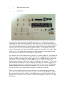
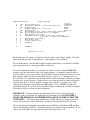
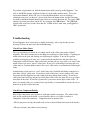
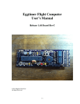
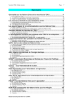
Eggtimer Flight Computer
Assembly Manual
Board Rev C
© 2013 Eggtimer Rocketry
All Rights Reserved
Before You Start…
• Go to our web site at www.eggtimerrocketry.com and download the latest Release Notes.
• Go to our web site at www.eggtimerrocketry.com and download the latest Assembly
Instructions.
• Read them thoroughly before starting… it will save you some grief later, we promise!
• We recommend that you apply the latest Flash Updates after validating your Eggtimer’s
operation; you should do this BEFORE you perform a Master Reset (since it may affect how
memory is used)
• Before you can program or fly your Eggtimer, you need to perform a Master Reset. See
Appendix A in the Eggtimer Users Guide for details.
~~~~~~~~~~~~~~~~~~~~~~~~~~~~~~~~~~~~~~~~~~~~~~~~~~~~~~~~~~~~~~~~~~~~~~
Thanks for buying an Eggtimer flight computer! We’re sure that you are ready get started, but
before you do you will need to get some tools together. The tools that you will need are:
___
Low-wattage soldering iron, 15W or less, with a fine tip
___
Fine rosin-core solder, .022”-.032”, 60/40 tin-lead or similar lead-free solder
___
Small needle-nose pliers
___
Small diagonal cutters
___
A small damp sponge for cleaning the tip of your soldering iron
___
A lighted magnifier, for inspecting solder joints (not essential, but very helpful)
___
A well-lighted place to work, preferably with a wood or metal surface,
also preferably not carpeted
Each installation step has a check-off line, we strongly recommend that you check them off as
you go, and that you perform the steps in sequence. We have listed the steps in order to make
it easiest to assemble the Eggtimer, deviating from them isn’t going to make your life any
easier.
About Soldering Your Eggtimer…
Assembling your Eggtimer isn’t that hard, but we recommend that you don’t choose it as your
first kit project. You must be able to solder small components using fine solder and get nice
shiny solder joints. If you have never soldered before, you need to learn anyway, because if
you are going to do rocketry electronics you’re going to be doing some soldering. If you want
to get into advanced projects like telemetry, you’re probably going to be doing a lot of
soldering. We recommend that you get a few small kits from Ramsey or SparkFun, put them
together, and hone your skills on them first. There’s a lot of fun stuff out there, so go for it!
We recommend using the finest solder that you can find, either .025” or .032” rosin-core
solder. We recommend Kester or Multicore brands, a good 60/40 solder (60% lead 40% tin)
works great and those brands an alloys are readily available. If you do not wish to use leaded
solder, or you can not due to environmental regulations, get the lowest melting non-leaded
solder you can find; if you want to read all about lead-free solder, go to:
http://www.psma.com/ul_files/forums/leadfree/aim_lead_free_guide.pdf
A low-temperature Sn/Ag/Cu alloy is best, look for one that melts at 217 °C or lower and is
suitable for high-vibration applications.
European Union countries have a regulation known as RoHS, “Restriction on Hazardous
Substances”, that prohibits the use of leaded solder in consumer products. Kits such as the
Eggtimer are exempt from this regulation, however we abide by the principle regardless. We
use unleaded solder paste when we mount the SMT components on the board, and all
components are certified by their vendors as being RoHS compliant. However, we do not
certify the Eggtimer as RoHS-compliant because we have no control over what solder alloy is
used to mount the other components. This does not currently apply to the US or Canada, but
who knows when it might be adopted here…
For soldering components on a board like the Eggtimer, we recommend a small pencil
soldering iron, about 15W. If you are only going to use it occasionally, Weller makes a decent
cheap 12W iron, it’s about $15. We like it, but the copper tips seem to oxidize and corrode
rather quickly compared to some more expensive irons; fortunately, the tips are replaceable
and cheap. Better would be a fancier soldering pencil with iron tips; those run about $30, but
they’ll last forever. The best iron would be a temperature-controlled solder station, they
typically start at about $50 for a cheap one and can go to a few hundred dollars if you want to
get really fancy. Weller makes a good one for about $50, if you make the investment that will
probably be the last soldering iron you will ever need to buy. These solder stations usually
have a little well with a tip-cleaning sponge, so they end up taking less room on your
workstation too.
You may also want to buy a portable battery-powered or butane soldering iron to have in the
field, in case you need to tin a wire or repair a solder joint in the field. They work fine, but we
recommend that you do not use them to assemble the Eggtimer, they generally do not put out
as much heat as the electric irons and you may not get really good solder joints, especially if
you use non-leaded solder which has a higher melting point than leaded solder.
Step 1: Sort the Components
Before you start soldering anything, you need to lay everything out and make sure that you are
familiar with all of components, and that you have everything. (Yes, we ARE human and
sometimes make mistakes… if you are missing something, let us know immediately so we can
send you whatever you need). You should have the following parts, check them off as you sort
them…
__
Qty
1
Description
Circuit board pre-populated with surface mount sensor and memory
__
1
Atmel ATMEGA328P-PU processor chip (big 28-pin IC)
__
2
MCT-6 Dual Optoisolators (8-pin chips)
__
2
TIP120 Transistors (3-pins)
__
1
3mm Red LED
__
1
3mm Yellow LED
__
1
Pizo buzzer element (round plastic component with two wires and a hole)
__
1
16.000 MHz ceramic resonator
__
2
820 ohm 1/8 watt resistors (bands are grey-red-brown)
__
1
1K ohm 1/8 watt resistor (bands are brown-black-red)
__
4
2.2K ohm 1/8 watt resistors (bands are red-red-red)
__
1
3.9K ohm 1/8 watt resistor (bands are orange-white-red)
__
4
4.7K ohm 1/8 watt resistors (bands are yellow-purple-red)
__
6
10K ohm 1/8 watt resistors (bands are brown-black-orange)
__
4
.1 uF multilayer ceramic capacitors (marked “104”)
__
1
10 uF electrolytic capacitor (tubular component with two wires,
one is marked “- - - - -“ on the side of the case)
__
1
6mm push button switch
__
1
6-pin header
Note that some of the components, notably the Atmel processor and the surface-mounted
components pre-soldered to the PC board are static sensitive, so you should avoid sources of
static electricity while you are handling them. We recommend that you assemble the Eggtimer
on a wood or metal surface unless you are fortunate enough to have a high-temperature antistatic mat (don’t buy one just to build the Eggtimer, however!) Avoid putting it on plastic
surfaces that generate static, and preferably put it together in a room that’s not carpeted. That
being said, it’s very unlikely that you will zap any of the components in the Eggtimer with
static electricity, but consider yourself notified of the possibility…
Also note that some of the components are polarized, i.e. it matters which way you put them in.
If you solder one of these components in backwards, the effect will range from something not
lighting up (LEDs) to nothing at all working (processor). It is CRITICAL that you test-fit the
parts before you solder, and that you make SURE that you have them pointed the right
direction before soldering. Like the old adage says, “Measure twice, cut once.” If you solder a
part onto the board incorrectly, it can be a minor pain to remove if it only has two pins, or it
can be virtually impossible for something with a lot of pins like the processor. The Eggtimer
Limited Warranty does not cover incorrect assembly, so if you mess up badly enough you
may end up having to get another kit and starting over; neither of us want that.
There are several different resistor values, so make sure you get the right ones in the right
place. They are marked on the boards, but once again you need to make SURE that you have
them in the right place before soldering. Unsoldering parts on a small circuit board like the
Eggtimer isn’t a lot of fun, even if you have a vacuum desoldering tool. Trust us, we’ve been
there before…
In general, you are going to assemble the Eggtimer from the lowest-profile components first
and work your way up to the taller components. This will make it easier to keep parts from
falling off the board as you turn it over to solder them. To help keep parts from falling out,
you can use a little paper masking tape to temporarily hold them in place until you solder them.
DO NOT use “Scotch”® tape or electrical tape for this; plastic tapes can pick up static
electricity, and electrical tape tends to leave a sticky residue.
If you have been doing this kind of thing for awhile, you have probably noticed by now that we
do not include sockets for the processor or the optoisolators. There are a couple of good
reasons for this. First, they add cost and weight, although not much. Secondly, they add
about ¼” to the height of the board, which can make it a tight fit in 29mm motor or BT-55
body tubes. Finally, and most important, components CAN be dislodged from sockets during a
flight due to acceleration and vibration. We have seen it happen, and the results are not pretty,
particularly if you are doing electronic recovery system deployment. Soldering these
components to the board completely eliminates this possibility. Neither the processor nor the
optoisolators are going to be damaged by the low-heat soldering that you will use to mount
them to the Eggtimer PC board, as long as you keep to our recommendations for the soldering
iron and solder.
Eggtimer Assembly Checklist
Before you solder anything, make absolutely sure that you have the correct part and that it is
inserted in the board correctly. The board has all of the component values, outlines, and
polarities silk-screened on the top, so there shouldn’t be any doubt about what goes where and
how. Nevertheless, if you have any questions about the assembly procedure, do not hesitate to
drop us a line at [email protected] before you solder the parts to the board. You
may have to wait a day for the answer, but it could save you a lot of grief later on!
The Eggtimer Limited Warranty does not cover damage to parts while attempting to desolder
them because you inserted something incorrectly. We spent a lot of time making sure that the
assembly instructions were clear, but once again if you have any questions about the assembly
procedures drop us a line at [email protected] before you solder.
___
Mount the Atmel ATMega328P-PU processor
Carefully remove the processor chip from the anti-static foam or tube in which it was shipped.
Identify the notch at one end of the chip, this notch needs to line up with the notch that’s
silkscreened on the PC board. Gently insert the chip into the holes, and turn the board over.
The holes are small, so you may have to wiggle it around a bit to get all 28 pins into them.
Solder ONLY two opposite corner pins, then turn the board upright again, and make sure that
1) you have the chip pointed in the right direction, and 2) the chip is seated completely against
the circuit board. If you made a mistake, you will have to carefully unsolder the chip and fix
the problem; two solder joints are a lot easier to fix then 28. If it looks good, turn it back over
and finish soldering the rest of the pins.
___
Mount the Optoisolators
Carefully remove the two MCT-6 optoisolator chips from the anti-static foam or tube in which
it was shipped. Identify the notch at one end of the chip, this notch needs to line up with the
notch that’s marked on the PC board. Some chips don’t have a notch, they have a dot instead;
the dot should line up with the notch marked on the board. Gently insert the chips into the
holes, and turn the board over. Solder ONLY two opposite corner pins of each chip, then turn
the board upright again, and make sure that 1) you have the chip pointed in the right direction,
and 2) the chips are seated completely against the circuit board. If you made a mistake, you
will have to carefully unsolder the chip(s) and fix the problem. If it looks good, turn it back
over and finish soldering the rest of the pins.
___
Mount the .1uF ceramic capacitors
Insert the four .1 uF ceramic capacitors (marked “104”) into the appropriate holes. These are
not polarized, so it doesn’t matter which way you mount them. Turn the board over and solder
them to the board. Trim the excess leads.
___
Mount the push button switch
Insert the push button switch into the holes on the board. It has a little kink in the leads, so it
will stand off about 1/16” if you have the kink centered in the middle of the hole. Note that
one side is a little longer than the other side, and it’s not polarized, so you can’t mount it
incorrectly. Turn over the board and solder the leads to the board.
___
Mount the RED (IND) LED
Insert the RED LED into the holes for the IND LED, make sure that the LONG lead is in the
hole maked “+”. LEDs are polarized, if you put it in backwards it will not work, so doublecheck! Turn the board over and solder the leads to the board. Trim the leads flush.
___
Mount the YELLOW (RDY) LED
Insert the YELLOW LED into the holes for the RDY LED, make sure that the LONG lead is in
the hole maked “+”. Double-check to make sure! Turn the board over and solder the leads to
the board. Trim the leads flush.
Mounting the Resistors
The resistors are going to be mounted vertically, so you will need to bend one lead back
against the body of the resistor in order to do this. They aren’t polarized, but we like to have
all of the color bands facing up to make it easier to identify them (the fourth band is a
“tolerance” band and will probably be the same color on all of the resistors except for the 1K
and the 3.9K resistor).
___
Mount the 1K Resistor (brown-black-red bands)
Bend one lead back on the 1K resistor. Locate its position on the board, and insert the resistor
in the board. Turn over the board and solder the resistor in place, trimming the leads flush
afterwards.
___
Mount the 2.2K Resistors (red-red-red bands)
Bend one lead back on each of the four 2.2K resistors. Locate their positions on the board,
and insert the resistors in the board. Turn over the board and solder the resistors in place,
trimming the leads flush afterwards.
___
Mount the 3.9K Resistor (orange-white-red bands)
Bend one lead back on the 3.9K resistor. Locate its position on the board, and insert the
resistor in the board. Turn over the board and solder the resistor in place, trimming the leads
flush afterwards.
___
Mount the 4.7K resistors (yellow-violet-red bands)
Bend one lead back on each of the four 4.7K resistors. Locate their positions on the board,
and insert the resistors in the board. Turn over the board and solder the resistors in place,
trimming the leads flush afterwards.
___
Mount the 10K resistors (brown-black-orange bands)
Bend one lead back on each of the six 10K resistors. Locate their positions on the board, and
insert the resistors in the board. Turn over the board and solder the resistors in place, trimming
the leads flush afterwards.
___
Mount the 820 ohm resistors (grey-red-brown bands)
Bend one lead back on each of the two 820 ohm resistors. Locate their positions on the board,
and insert the resistors in the board. Turn over the board and solder the resistors in place,
trimming the leads flush afterwards.
___
Mount the 10 uF electrolytic capacitor
Insert the 10 uF electrolytic capacitor into the holes on the board, making sure that the lead
with the “- - - -“ markings next to it is inserted OPPOSITE the hole marked “+”. The “- - - - “
band should be facing away from the processor chip. Double-check to make sure that you
have this inserted correctly! Turn over the board and solder the leads to the board. Trim the
leads flush.
___
Mount the 6-pin header
Note that the header is not symmetrical, one side of the pins is a little longer than the other
side. Insert the header into the holes at the front of the board, using the SHORT side. The
LONG side should be on the TOP side of the board. You will probably need to use masking
tape to hold it in place, you want to make sure that it’s absolutely vertical and that it’s seated
completely against the board. Turn over the board and solder the pins to the pads.
___
Mount the pizo buzzer
Insert the pizo buzzer into the holes on the board. It is not polarized, so it doesn’t matter which
way you mount it. Turn over the board, and solder the leads to the pads. Trim the leads flush.
___
Mount the resonator
Insert the 16.000 MHz resonator into the holes on the board (marked “XTAL”), making sure
that it seats completely. You may need to use some masking tape to hold it in place. It is not
polarized, so it doesn’t matter which way you mount it. Turn over the board and solder the
leads, and trim if necessary.
___
Mount the transistors
Hold one of the TIP120 transistors horizontally with the metal tab facing down. The plastic
side of the transistor with the writing should be facing up. With a pair of needle nose pliers,
bend the leads upwards 90°, at the point where the leads get skinnier. Repeat for the other
transistor.
Turn over the PC board and insert them into the board FROM THE BOTTOM SIDE, they
should be facing the front of the board (the side with the header). If you bent the transistor
leads correctly, the plastic side of the transistors will be laying against the bottom of the PC
board. Turn over the board and solder the leads to the pads ON THE TOP SIDE OF THE
BOARD. This is the only component that is soldered on the top of the board. Trim the leads
flush.
Assembly of your Eggtimer is now complete. Inspect the solder side of the board carefully,
looking for “cold” solder incomplete solder joints. Cold solder joints appear dull instead of
shiny, and may appear as blobs of solder and not have the nice “wetting” of the pad that you
will see with good joints. A magnifying light is good for checking the board. If you want, you
can also use some spray flux remover on the component side of the board, a small brush like an
old toothbrush will help remove any flux residue. This will make it a little easier to spot for
incomplete solder joints. Warning: DO NOT spray flux remover directly on the top side of the
board, it may damage the pressure sensor!
Note: When you first get your Eggtimer, the flight memory is NOT initialized.
Please see Appendix A in the Eggtimer Users Guide for instructions on how to
clear the flight memory by performing a Master Reset. You will need to do this
before you can program or fly the Eggtimer, or unpredictable results may
follow!
About Wiring Your Eggtimer
The Eggtimer does not use terminal blocks to mount the wires, instead there are solder pads to
which you can solder #24 stranded wires. The wires in terminal blocks CAN work loose with
the forces of flight, so it’s better to solder the wires on the board and to whatever switches or
battery clips you are using. If you are going to use removable connectors such as for batteries,
the connectors used for RC model servos (Deans, Futaba, Airtronics, etc.) work very well; just
buy a “servo extension” and you will get a 12” or longer pigtail with both a male and female
connector. We recommend against using slide switches for power, reset, etc., they have a
tendency to “bounce” under high G forces, which is going to cause your Eggtimer to lose
power or reset and will ruin your whole day at the field. See the Eggtimer User’s Manual for
some suggestions on switches, shunts, and jumpers.
You will need to solder some wires to the Eggtimer board in order to test it, we like using the 4
stranded twisted-pair wiring that’s used with Ethernet network cables. Get the cheapest ones
you can find (we’ve even seen them in dollar stores!), cut off the ends, and carefully strip about
1’ of the jacket off at a time until you get the length you want. The nice thing about these
cables are that the wires are color-coded so it’s going to make it easier to trace your wiring, and
the wires are twisted together so it’s easier to route them. They are also in solid-striped pairs,
so it’s easy to make sure that anything that’s polarized (such as the battery connections) is
hooked up properly… by convention, solid goes to the “+” side, striped goes to the “-“ side. If
you can find it, the “plenum rated” cable is the best… the jackets are heat-resistant Teflon ®
instead of the more common PVC. Note: we strongly recommend that you tin the wires
before soldering them to the Eggtimer board. This prevents loose strands of wires from
bridging the pads, or coming loose and lodging somewhere on the board (like underneath the
processor chip!). Trim the wires after soldering.
Testing your Eggtimer
You can test your Eggtimer very easily on your workbench, you do not need to install it into a
rocket first with a full-blown electronic deployment setup. All you need to do is to solder
some “pigtail” wires to the board, 12” is a good length. At a minimum, you will need to
connect the battery and short the switch wires together, but you can also test the deployment
circuit easily as well. You will need a 3v-4v battery to power the Eggtimer (two AA batteries
works well for testing), and optionally a separate battery for deployment testing (a 9v battery
works fine).
IMPORTANT: The Eggtimer is designed to be connected directly to a 3V-4V battery, such
as two “AAA” batteries, a 3.7V 1C LiPo battery, a 3V lithium battery such as a CR123 or
CR5, or a 3.6v NiMH battery pack. It will NOT work with a 9V battery. If you connect the
Eggtimer’s “3V” battery pads to a 9V battery, you WILL damage it irreparably. If you
are using a variable-voltage power supply for testing, make SURE that you are using a suitable
voltage. Damage due to high voltage is not covered by the Eggtimer’s Limited Warranty.
You will need to use an USB-TTL interface cable, conveniently the Eggtimer comes with one.
The header is pinned for a standard FTDI-type 6-pin connector, but you can also use a cable
with individual pins (TX, RX, GND) by simply plugging those pins into the corresponding pin
on the connector. You will need to install the driver software for the USB-TTL interface that
you are using on your computer before you can use it. The one that comes with the Eggtimer
uses a Prolific PL2303 USB-serial chip, your operating system may already have the drivers
installed for it but if it does not you can get it at
http://prolificusa.com/pl-2303hx-drivers/
They have drivers for Windows (x86 and x64 versions), MacOS, and Linux. Since the
Eggtimer uses a serial terminal interface, this means that you can use just about any computer
you want with it. See the Eggtimer Users Manual for suggestions on suitable terminal
software, many of them are freeware.
The USB-Serial cable that comes with the Eggtimer has three separate wires rather than a 6-pin
FTDI-standard header. You need to connect it to the Eggtimer as follows, depending on the
colors of your cable’s pins (we have several suppliers and the colors are unfortunately not
standardized.
Black – Red- White Cable:
BLACK - Eggtimer “GND” pin
RED – Eggtimer “RX” pin
White – Eggtimer “TX” pin
Black – Green – White Cable:
BLACK - Eggtimer “GND” pin
GREEN – Eggtimer “RX” pin
White – Eggtimer “TX” pin
Orange – Blue – Red Cable:
ORANGE – Eggtimer “GND” pin
BLUE – Eggtimer “RX” pin
RED – Eggtimer “TX” pin
Plug the serial interface into a USB port, and confirm that your OS assigns a serial port to it.
Set the serial port to 19,200 baud, 8 bits, 1 stop bit, no parity, and no handshaking. Open up
your terminal program, select the serial port that your OS assigned to the USB interface, and
connect. Connect power to the Eggtimer, after a few seconds the IND light should come on, it
should start beeping, and you should see the programming screen:
Eggtimer Build_1.47
A
B
D
E
F
G
100
10
100
2
500
0
400
1
0
H
I
J
K
1
1
0
0
C
O
Flight Settings
T:23.50
LDA <50-500 by 50>
P:97804.00
Burn/Coast Samp/sec: <4,5,8,10,15,20,25,33>
A:975.39
Interval (ms)
Main:0
Descent Samples/sec <1,2,4,5,10>
CHB:0
Interval (ms)
Batt:3.12
Main Enable <0-Off, 1-IGN, 2-Servo CCW, 3-Servo CW>
Main Altitude <100-2000 by 50, 0 @ Apogee>
Main ON-Time <1-9,0-Cont.>
CHB Enable <0-Off, 1-IGN, 2-Servo CCW, 3-Servo CW,
4-Airstart, 5-Airstart w/o Breakwire>
CHB ON-Time <1-9,0-Cont.>
Burn Timer <1-20>
Airstart Delay <0-9>
Telemetry
Comments:
Options: Esc, A-O, ?
Hit the Enter key a few times, you should see the P: and A: values change slightly. If it looks
pretty much like this, then Congratulations! Your Eggtimer is now working.
To test the Breakwire, short the BW terminals together and hit Enter, you should see the BW:
status change from 0 to 1, meaning that BW was detected.
To test the deployment channels, you will need to connect a battery to the BCHA/BCHB
terminals, and add some kind of load to the output channels. A common 9v battery makes a
good test battery, you can get a battery clip from Radio Shack and simply tack-solder it to your
tinned pigtails. Make sure that you match the polarity, red goes to “+” and black goes to “-“.
For a test load, we recommend using the bulbs from a strand of miniature Christmas tree lights
(the little ones, not the big ones!), simply unravel a few from the strand, cut them off from the
strand leaving about 1” of wire on them, and strip and tin about 1/8 ” from the wire. Tacksolder them to the pigtails of the Main and CHB channels. Note: NEVER test with a live
deployment charge! If you need to test your battery/igniter combination, use ONLY an igniter,
preferably at least 5 feet from you and the Eggtimer.
IMPORTANT: You must connect some kind of resistive load across the deployment
terminals, such as a Christmas tree light bulb or #32 nichrome wire. DO NOT SIMPLY
SHORT THE TERMINALS TOGETHER WITH A PIECE OF WIRE TO TEST THE
CONTINUITY! If the deployment channel fires, it WILL damage the output transistors if
you are using a battery such as a LiPo that is capable of sourcing more than 5A of current.
When you bring up the Eggtimer programming screen, hit Enter, and both the CHB and Main
statuses should change from 0 to 1, indicating that there is continuity on those channels. If you
remove one of the bulbs, the status for that channel should go from 1 to 0.
To perform a deployment test, hold the button down while powering on the Eggtimer. You
will see the MON> prompt, which means that it’s in the utility monitor mode. To test the
deployment channels, hit the “M” key to select the Main channel, and you will hear a
continuous tone to let you know it’s in test mode. Press the button down, and the Christmas
tree bulb on the Main channel should come on for two seconds then turn off. To test the CHB
channel, repeat the procedure, but hit “B” key to trigger the CHB channel. The CHB light
should come on for two seconds, then shut off. If both of these work, then your Eggtimer is
100% operational.
Troubleshooting
If your Eggtimer doesn’t work after assembly and testing, take a deep breath, get out a
beverage to clear you mind, and start troubleshooting…
Check Your Solder Joints
The very first thing you should do is to check out all of the solder joints under a lighted
magnifier. The most common reason for things not working are solder bridges, i.e. putting too
much solder on the pads and shorting two adjacent pads together. You can also get into
problems by bridging pads with “vias” on the board, the smaller holes that don’t have any
components soldered to them. Most of the holes and the pads are very small, so it doesn’t take
much solder to get a nice “tented” solder joint. If you get a solder bridge, heat it up and use a
solder wick or a vacuum bulb to remove the excess; afterwards, we recommend resoldering the
joints.
Another thing to look out for is “cold” solder joints, they look dull and blobby compared to a
nice shiny “tented” solder joint. If you have a cold solder joint, it won’t conduct well; at the
low power that the Eggtimer uses this could easily keep things from working. If you have a
cold solder joint, heat it up and put just a little bit of solder on it, the main idea is to get a little
more flux on the joint. If you have separate flux, you can use that in place of the solder. If
there’s too much solder, use a solder wick or (preferably) a vacuum bulb to remove the excess,
then heat it up and resolder the joint.
Check Your Component Polarity
Most of the components aren’t polarized, with some notable exceptions. The outline of the
parts is silk-screened on the board, so you should be able to see readily if you have a
component soldered in backwards. Components that are polarized are:
• The 28-pin processor chip; the notch needs to face to front of the board (towards the header)
• The opto-isolators; the notches need to face up
• The transistors, the plastic side should be laying against the bottom of the PC board with the
tabs facing forwards (towards the header)
• The 10uF electrolytic capacitor, the side marked “-------“ should be OPPOSITE the side
marked “+” on the board (away from the processor chip).
• The LEDs, the long leads should have been inserted in the pad marked “+”. Unfortunately,
once you clip the leads it may be difficult to tell if you have inserted it correctly.
If you inserted a component incorrectly, you will have to carefully unsolder it, clear any solder
residue from the holes, and resolder it. This can range from being relatively easy for some of
the larger two-leaded components (LEDs, 10uF capacitor) to very difficult for the processor.
If you find that a component was soldered incorrectly, you will have to use a vacuum bulb or
vacuum desoldering tool to unsolder it. If it’s a two-leaded component like an LED it may not
be terribly difficult, if it’s the processor or even one of the 8-pin opto-isolators then you are
going to have a major chore on your hands. We cannot stress enough that you need to check
the orientation of the parts before you solder them. The Eggtimer Limited Warranty does not
cover damage to a component while attempting to unsolder it, so make take your time and
make sure you get it right before you solder.
Check Your Power Supply
Make sure that you are using one of the recommended batteries to test with. For testing, we
like to use two AA alkaline batteries in a little holder; they’re really cheap and they’ll last a
long time. Make sure that you have the polarity correct: The RED wires must go to the “+”
side and the BLACK wires must go to the “-“ side.
Check Your Power Switch
If you have a power switch, make sure that it’s a simple SPST type so that when you close it
it’s simply bridging the SW terminals. You don’t HAVE to use a power switch; if your
battery is removable (i.e. you are using some kind of connector between the battery and the 3V
pigtails) then you can simply solder a wire across the SW terminals. We do NOT recommend
this for complex applications like multiple deployment using pyro charges with HPR rockets,
and definitely not for airstarting. Check the Eggtimer User Guide for switch recommendations.
If It Still Doesn’t Work…
There is, of course, always an outside chance that you have a bad component. We test each PC
board and the surface mounted components before they leave us, and we also test each
processor, transistor, and opto-isolator. Nevertheless, it is always possible that something may
be wrong; there may be a bridge on the PC board itself, etc. If you have gone through all of the
troubleshooting steps and the board still doesn’t work, let us know at
[email protected] . A high-resolution picture (5 megapixel or better) of both
sides of your circuit board and a description of the problem would be very helpful…
Appendix A – Typical Connections
Below is a picture from a test setup that we have for the Eggtimer. It is very typical of what
you would use in a multiple-deployment rocket… a 3.7V LiPo battery for the Eggtimer’s
computer, and a 9V battery for the deployment channels. You can see that the 9V battery is
connected to both of the deployment channels’ battery pads (BCHA, BCHB). We are using
miniature Christmas tree lights for the igniter test load, they work very well and are cheap. We
have hooked up all three external LEDs (READY, ALED, and BLED), an external pizo buzzer
(BUZ), and a switch on the SW terminals. (It’s a cheap slide switch, we recommend that you
do not fly one of these, get a Schurter 033.4501 rotary switch instead).
We have also connected a pigtail to the RST line. In a real flight, you can twist these together
and have them outside the rocket; to start the flight sequence, you simply take them apart and
tape them up so they won’t short during the flight. We have not connected the Breakwire
(BW) terminals, they are used only for airstart flights; that subject is covered extensively in the
Eggtimer Users Guide.