1
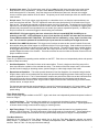
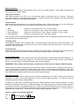
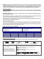
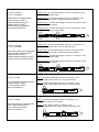
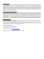
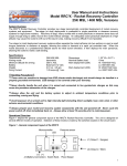
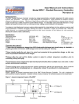
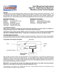
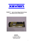
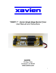
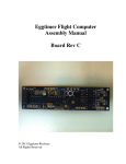
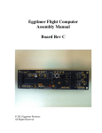
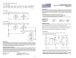
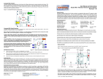
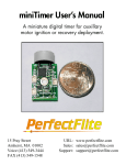
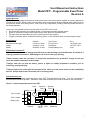
User Manual and Instructions Model PET² - Programmable Event Timer Revision A System Overview The PET2 provides a highly advanced and versatile dual-event timing control system targeted for rocketry applications. The design of the PET² utilizes a RISC microcontroller with a precise internal factory-calibrated 4MHz system clock for accurate and reliable event timing control. Each timer is fully independent, providing extremely flexible solutions for any timing application. Just some of the applications that can be achieved with the PET² timer include: • Precise booster separation and sustainer ignition of multi-stage composite powered rockets • Ignition of secondary composite motors after primary motor ignition for airstarted boosts • Fail safe backup and redundancy of primary rocket recovery control systems • Triggering a camera shutter, audible/visual tracking device, or other electrical device at various stages of flight Specifications Arming Mode Minimum G-load trigger Weight Battery G-switch 2.6 G's for 0.5 sec 33 grams / 1.6 oz. external 8-12 VDC Test Current Firing Current Dimensions Nominal Battery load 80 µa 1.25 A @ 0.5 sec. 1.38" W x 3.85" L 15ma IHandling PrecautionsI IThese units are sensitive to damage from ESD (electro-static discharge) and should always be handled in a properly grounded environment. ESD damage is not covered under your warranty. INever directly handle the unit when it is armed and connected to live pyrotechnic charges as this may cause the premature detonation of the charges. IAlways allow the unit and the battery system to adjust to ambient temperature conditions prior to connecting, arming and flying. IAlways prepare your rocket with the unit powered off. Never cycle the power switch off, then immediately back on. Always allow at least 10 seconds prior to restoring power. Operational Overview Figure 1 depicts the general component layout of the PET2 Programmable Event Timer. The unit is designed for several different modes of operation. Selection of these modes is made by the switches located on the circuit board. Figure 1 - General component layout of the PET² Piezo Switches Timer 2 Switches Timer 1 THIS END FORWARD Timer 2 output Timer 1 output Battery input G-switch Pull-pin input MCU Multiplexer 1 The switches are labeled 1 through 8 accordingly for each timer. The ON position for the switches is also labeled, indicated by a small arrow depicting the appropriate ON position. The following table describes the switch functions and the corresponding modes of operation. The timers are functionally identical, so the table applies to the setting for both timer events. Table 1 - Timer configuration switch settings Function Triggering mode selection Switches/Positions SW. 1 SW. 2 Off Off On Off Off On On On Mode of Operation Trigger on G-switch Close event (initial G force detection) Trigger on G-switch Open event (deceleration) Trigger on Pull-pin event (break wire) Trigger on G-switch Close AND Pull-Pin event Operating mode selection SW. 3 Off On Operates with a one-shot output (single output event) Operates with a repeated cycle (repeats at timing interval) Timing Range selection SW. 4 Off On Low timing range selected (0.5 - 8 sec. @ 0.5 sec. intervals) High timing range selected (2 - 32 sec @ 2 sec. intervals) SW. 5 SW. 6 SW. 7 SW. 8 Off Off Off Off On Off Off Off Off On Off Off On On Off Off Off Off On Off On Off On Off Off On On Off On On On Off Off Off Off On On Off Off On Off On Off On On On Off On Off Off On On On Off On On Off On On On On On On On Low (sec.) / High (sec.) 0.5 2 1.0 4 1.5 6 2.0 8 2.5 10 3.0 12 3.5 14 4.0 16 4.5 18 5.0 20 5.5 22 6.0 24 6.5 26 7.0 28 7.5 30 8.0 32 Time Base Selection* *Note: All timing values reflect the inclusion of the 0.5 second de-bounce timer (refer to G-switch close event). IMPORTANT – All timer configuration switch settings MUST be made prior to powering up the unit. They are read at power up ONLY. Set ALL switch positions prior to turning the unit on. Timer Functional Description Since the PET² provides a very flexible and versatile timing system, it's important that you fully understand how it functions. The following describes the functional timing operations of the PET². Timer Triggering Modes There are (4) distinct modes of triggering available on the PET². Each timer can independently select any of the triggering modes: • G-switch Close event - The onboard G-switch will close when the rocket vehicle reaches at least 2.6 G's of acceleration. This acceleration level must be maintained continuously for 0.5 seconds in order to qualify as a valid close event and signify the launch of the rocket vehicle. This 0.5-second interval is referred to as a "de-bounce" time interval. The de-bounce is intended to filter out any inadvertent movement after arming that might accidentally trigger the unit. The primary use for G-switch Close event is to detect the initial launch of the rocket. 2 • G-switch Open event - The G-switch open-event will occur after the initial close event when the rocket vehicle drops below 2.6 G's of acceleration. The open event must be preceded by a valid G-switch close event (debounce time period of 0.5 seconds). Once the close event conditions have been met, the open event trigger occurs on the first open transition of the G-switch. The primary use of the G-switch open event is to detect rocket motor burnout. • Pull-pin event - The Pull-pin trigger works physically on a breakwire circuit, so when the input transitions to an open circuit the timer will start. The PET² applies the same de-bounce time period of 0.5 seconds to the Pull-pin input as well. The inputs must maintain a continuous open circuit for 0.5 seconds. The primary use for the Pull-pin inputs are for low thrust flights where the minimum 2.6G's are not attained at launch, or possibly for triggering after airframe body components have separated from one another (for instance at parachute ejection). In addition, the Pull-pin functions as a convenient trigger for bench testing and verification. IMPORTANT: If Pull-pin triggering has been selected, the Pull-pin inputs MUST BE CLOSED prior to powering up the PET². If the unit detects an open circuit at power up, the PET² will enter the Pull-pin Alarm Lockout Mode and WILL NOT FUNCTION. The Pull-Pin Alarm is indicated by a long, slow 0.5 second chirp rate. The unit must be powered off and the Pull-pin inputs must be corrected prior to flight of the unit. • G-switch Close AND Pull-pin event - This trigger event functions the same as the normal G-switch Close event, the exception being that it must happen in conjunction with the Pull-pin input trigger. Both conditions must be met simultaneously and satisfy the de-bounce timer period of 0.5 seconds. The same Pull-pin Alarm condition applies to this trigger mode as well. When using this mode, the Pull-pin input can act as a "safety" switch, as no trigger is possible despite the status of the G-switch. This mode could also be used to inhibit the G-switch Close event until proper conditions are met. Timer Operating Modes There are (2) distinct timer operating modes available on the PET². Each timer can independently select and operate in either of these two modes: • One Shot Operation - This mode functions as the name implies. There is a single one time firing event of the timer output after the expiration of the selected time delay. The duration of the timer output event is 0.5 seconds. Use this mode for staging or airstarting motors, ejection charges, or other single output event needs • Repeat Interval Operation - This mode operates identical to One Shot Operation, the exception being that after firing the timer output, the unit restarts the time delay and repeats the timing/firing process continuously as long as power is applied to the unit. The 0.5 second duration output event period is the same time as the initial de-bounce timer period, thus the unit can maintain repeat timing intervals identical to the initial timing interval that was compensated with the de-bounce timer. A typical use for Repeat Interval mode could be driving a camera shutter, a flasher device, or beeper device. The shortest repeat period that can be selected is 1 second (0.5 second output period + 0.5 second delay). When the timer is set for a 0.5 second duration in Repeat Interval mode, it is automatically overridden with a 1 second period setting. Timer Range Selection There are (2) timing ranges available on the PET². Again, each timer can independently select and operate in either of these two ranges: • Low Timing Range - The low timing range enables you to program the time base for short duration periods between 0.5 and 8 seconds. The timing increments in low range mode are 0.5 seconds each. Typical applications of shorter duration timing events would be staging or clustering events. • High Timing Range - The high timing range enables you to program the time base for long duration periods between 2 and 32 seconds. The timing increments in high range mode are 2 seconds each. Typical applications of long durations timing events would be recovery system backup deployment of drogue or main parachutes. Time Base Selection Depending on the setting of the Timer Range switch (low or high), the Time Base Selection switches can specify delays from 0.5 - 8 seconds or 2 - 32 seconds. The delay times specified Table 1 include the de-bounce time of 0.5 seconds. Refer to Table 1 for the proper time base settings. 3 Modes of Operation The PET² has several distinct modes throughout the course of its normal operation. These modes of operation are easily identified by the piezo beeper. Power-up annunciation After initially powering on the PET² unit, it will annunciate (beep) a continuous tone for 3 seconds. During this annunciation period, you can transition switch position 1 on either of the timer DIP switches to enter the input testing mode (refer to the Input Test Diagnostics description). Pre-launch state After the power-up annunciation, the unit enters the pre-launch mode. While in this mode, the unit will continuously chirp out the continuity status of the timer outputs (at a rapid rate) once per second as follows: • • • • Beep Beep Beep Beep Pause Beep Beep Beep Beep Powered on / No continuity on Timer 1 or Timer 2 outputs Powered on / Continuity on Timer 1 output / No Continuity on Timer 2 output Powered on / No Continuity on Timer 1 output / Continuity on Timer 2 output Powered on / Continuity on Timer 1 and Timer 2 outputs The unit also monitors the selected triggering source(s) as selected. After any triggering condition has been met, the timer transitions into Countdown state. Countdown state Once triggered, the timer enters countdown state. The piezo chirps at a very fast rate (10 chirps per second). The countdown state remains active until both timing events have completed their initial timing cycle. After this the unit transitions to Post Event state. Post Event state At this point, the PET² has completed the initial countdown of both timer events. The piezo will chirp out the continuity status of the timer outputs (at a slower rate) once per second in the same fashion as pre-launch state. Input Test Diagnostics The unit can also be placed into a test mode to verify the basic operation of the DIP switch inputs and Multiplexer. To place the unit into input test mode, toggle SW. 1 of either timer's DIP switches during the power up annunciation period. The unit will continue to operate in the test mode until it is powered off. IMPORTANT: After selecting input test mode, you must power off the unit prior to flight or additional testing. Once the input test mode is selected, the unit will read each switch in numerical order (1 through 8) and chirp out a "zero" chirp (long beep) for a switch in the OFF position, or a "one" chirp (short beep) for the ON position. After it has read all eight switches, it will pause for 2 seconds and restart the test. You can change the switches during this test to ensure that all the configuration switches are being read correctly by the MCU. Timer Bench Testing It is recommended you become familiar with the operational characteristics of the PET² by doing some bench test operations. The timer can be easily triggered by use of the pull-pin trigger (breakwire). You can then verify the selected timing intervals and/or timing operation. In addition it's a good idea to periodically test the timer output channels to ensure they are functional. A useful accessory for testing the outputs are 12 volt DC panel lamps. The lamps will allow you to verify the proper operation of the outputs without the use of pyrotechnic devices. An LED with a current limiting resistor can be used in place of a lamp; however, you have to observe the diode polarity when connecting to the output terminals. A 470 ohm resistor is suggested when using an LED. Connect the LED for output testing as depicted in Figure 2. Figure 2 - Output Test connections with LED CH1 (+) or CH2 (-) 4 Wiring / Mounting Considerations There are several factors to consider when it comes to the construction, mounting, wiring and arrangement of the PET² in your rocket airframe. Careful planning during the construction and preparation of your rocket will improve your chances for successful operation. IMPORTANT: Always load test your battery system prior to flight to ensure adequate power for reliable operation and ignition of the output events. To load test a battery, you will require a DC multimeter capable of DC Amp measurement with 10 Amp capability. A 9volt battery can easily source in excess of 5 Amps. Briefly connect the meter leads across the battery terminals to measure the DC current capacity. If the measurement is close to or drops below 2 Amps, do not use the battery. Some batteries have built in testers; however, it is still recommended that a meter be used for testing. Battery Considerations Though the unit is intended to operate with a standard 9-volt alkaline battery, the user may elect to power the PET² with a different battery source. The voltage requirements for the PET² battery source is 8 to 12 Volts. DO NOT EXCEED 12 VOLTS OR DROP BELOW 8 VOLTS. Nominal load during operation is about 15 ma; and during output firing, the unit requires upwards of 2 Amps. ALWAYS PAY CLOSE ATTENTION TO THE BATTERY POLARITY (+ AND -) WHILE CONNECTING YOUR WIRING TO THE PET². If you're driving an external realy with the PET², an external diode across the relay coil is recommended as shown in Figure 3 to protect against inductive load transients. IMPORTANT: Inadequate sizing of an external battery system can damage the unit or cause the unit to malfunction. Always pre-test your battery system design prior to launch. Figure 3 - Standard Wiring and Relay Drive Connections Event 1 (- ) (+) Battery THIS END FORWARD THIS END AFT Event 2 Power switch (normally open) Pull-pin input (Normally closed) 1N4001 or equivalent + - (+) (-) Recommended Relay Connection Mounting Considerations The PET² can be mounted with standard #4 screw hardware. Ensure that it is mounted securely to a rigid component of the rocket airframe. The mounting hole pattern is shown in Figure 4: Figure 4 - Mounting hole pattern and clearance requirements 3.60" AFT END VIEW 0.120" (typical) 0.55" 1.13" .75" .53" 1.38" 5 IMPORTANT: Please note the orientation of the PET² in the rocket airframe. The PET² has a Forward End and Aft End marked clearly on the top side of the circuit board. You must orient the Forward End of the PET² TOWARD THE NOSE of the rocket. Also ensure that the PET² is mounted parallel to the center axis of the rocket. Failure to mount the unit as described will prevent the onboard G-switch from operating properly. E-matches and Igniters The topic of e-matches and igniters is often overlooked and not given a proper evaluation. Improper selection or improper application of e-matches and igniters can result in failure of the timing events and potentially result in damage or loss to your rocket IMPORTANT: Always ground test the type of e-match or igniter you'll be using under actual flight conditions prior to committing to flight. Improper selection of an e-match or igniter will result in a malfunction. Always use an e-match that is suited for the test and firing conditions of the RRC² unit (e.g., do not use a high current device). Always check your e-match, igniter, or flash bulb devices for continuity and proper resistance prior to using them under testing or actual flight conditions. Selecting an adequate E-match The PET² has been tested and flown with several commercially available e-matches. The PET² was also tested with a cluster of (4) Oxral Ematches in parallel. When selecting an e-match supplier, refer to the "Specifications" section for the typical test current and firing current of the PET² to ensure the device you'll be using can be used reliably. Refer to Table 3 for adequate commercial e-match suppliers for the PET². Table 3 - Recommended E-match suppliers Daveyfire Inc. 7311 Greenhaven Dr, Suite 100 Sacramento, CA 95831-3572 Tel: 916.391.2674 Fax: 916.391.2783 Model Daveyfire 28B Daveyfire 28BR Daveyfire 28F Oxral Resistance 1.6 ± 0.3 ohms 1.6 ± 0.3 ohms 1.6 ± 0.3 ohms 2 ohms (nominal) OXRAL Inc. (Luna-Tech) PO Box 160 Owens Cross Roads, AL 35763 Tel: 205.725.4226 Fax: 205.725.4811 Test Current 20 ma (0.020 Amp) max 20 ma (0.020 Amp) max 20 ma (0.020 Amp) max 25 ma (0.025 Amp) max Firing Current 370 ma (0.37 Amps) min 370 ma (0.37 Amps) min 1.00 Amp min 500 ma (0.5 Amp) min Wire Color White Orange Black Red/Blue Example Applications with the PET² The following examples are just some of the possibilities that can be achieved through application of the PET². Symbol Legend PET² Motor PET² Avionics Separation charge Parachute Altimeter/Accelerometer *NOTE: Refer to the Timer Functional Description on pages 2 & 3 for a detailed explanation of the PET² operations and switch settings. Basic 2-stage rocket Suggested Timer Setup* (1) PET² in sustainer Timer1: G-switch OPEN trigger / One shot / Low Range / 0.5 sec. Use for booster separation charge Booster ignition via launch system Booster recovery via motor ejection Sustainer separation/ignition via PET² Sustainer recovery via motor/avionics Timer2: G-switch OPEN trigger* / One shot / Low Range / 0.5 sec. Use for sustainer motor ignition PET² Avionics 6 Advanced 2-stage rocket Suggested Timer Setup* (1) PET² in booster (1) PET² in sustainer Booster Timer 1: G-switch OPEN trigger / One shot / Low Range / 0.5 sec. Use for booster separation charge Booster ignition via launch system Booster recovery via PET² Sustainer separation via PET² Sustainer ignition via PET² Sustainer recovery via avionics Recovery Backup via PET² Booster Timer 2: G-switch OPEN trigger / One shot / Low Range / 2 sec. Eject booster recovery system 2 seconds after booster shutdown Sustainer Timer 1: G-switch OPEN trigger / One shot / Low Range / 0.5 sec. Use for sustainer motor ignition Sustainer Timer 2: G-switch OPEN trigger / One shot / High Range / 20 sec. Use for sustainer recovery system backup Avionics PET² PET² 2 stage rocket with Airstart Boosters Suggested Timer Setup* (1) PET² in booster (1) PET² in sustainer Booster Timer 1: G-switch CLOSE trigger / One shot / Low Range / 1 sec. Ignites outboard booster motors 1 sec. into main motor burn Main booster ignition via launch system Outboard booster ignition via PET² Booster recovery via PET² Sustainer separation/ignition via PET² Sustainer recovery via motor/avionics Booster Timer 2: G-switch OPEN trigger / One shot / Low Range / 2 sec. Eject booster recovery system 2 seconds after booster shutdown Sustainer Timer 1: G-switch OPEN trigger / One shot / Low Range / 0.5 sec. Use for booster separation charge Sustainer Timer 2: G-switch OPEN trigger / One shot / Low Range / 0.5 sec. Use for sustainer motor ignition PET² Avionics PET² Advanced 2 cluster Airstart rocket Suggested Timer Setup* (1) PET² in rocket Timer 1: G-switch CLOSE trigger / One shot / Low Range / 1 sec. Ignites 1st cluster booster motors 1 sec. into main motor burn Main motor ignition via launch system 1st cluster ignition via PET² nd 2 cluster ignition via PET² Recovery via avionics Timer 2: G-switch OPEN trigger / One shot / Low Range / 0.5 sec. Ignites 2nd cluster booster motors after booster/1st cluster shutdown Avionics PET² Camera rocket with sonic locator Suggested Timer Setup* (1) PET² in rocket Timer 1: G-switch CLOSE trigger / Repeat / Low Range / 1 sec. Drives camera shutter at 1 sec intervals Main motor ignition via launch system Timer 1 drives camera shutter Timer 2 drives sonic locator Recovery via avionics Timer 2: Pull-pin trigger / Repeat / Low Range / 2 sec. Drives high decibel piezo horn / trigger at recovery separation event PET² Avionics 7 Product Warranty Missile Works Corporation has exercised reasonable care in the design and manufacture of this product and warrants the original purchaser that the PET² Programmable Event Timer is free of defects and will operate at a satisfactory level of performance for a period of one year from the original date of purchase. If the system fails to operate as specified, then return the unit (or units) within the warranty period for repair or replacement (at our discretion). The system must be returned by the original purchaser and be free of modification or any other physical damage which renders the system inoperable. Upon repair of replacement of the unit, Missile Works Corporation will return the unit postage paid, to the original purchaser. Product Disclaimer and Limit of Liability Because the use and application of this equipment are beyond our control, the purchaser or user agrees to hold harmless Missile Works Corporation and their agents from any and all claims, demands, actions, debts, liabilities, judgements, costs, and attorney fees arising out of, claimed on account of, or in any manner predicated upon loss or damage to property of, or injuries to or the death of, any and all persons arising out of the use this equipment. Due to the nature of electronic devices, the application and environments for those devices, the possibility of failure can never be totally ruled out. It is the responsibility of the purchaser or user of this equipment to properly test and simulate the actual conditions under which the device is intended to be used to ensure the highest degree of reliability and success. Rules to live and fly by 1. Before you use the PET² Programmable Event Timer, make sure you have read and understand all the instructions, operations, and warnings contained herein. 2. Do not alter the system in any way, as this voids the warranty and could render the system inoperable or unreliable. 3. Always fly within the guidelines established by either the National Association of Rocketry or the Tripoli Rocketry Association whenever you participate in hobby rocketry activities. Missile Works Corporation P.O. Box 740714 Arvada CO 80006-0714 Tel: 303.426.1462 Fax: 303.426.1428 On the World Wide Web @ www.missileworks.com Copyright 2001 by Missile Works Corporation. All rights reserved 8