1
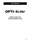
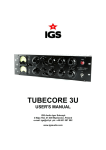
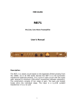
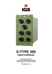
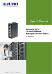
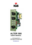
IPS-R E M OT E - U S E R MA N U A L
Remote Control Module for Integrated Power Systems
Unpacking and Inspecting Your Product
•
Before installation, please inspect the unit. Be sure that •
nothing inside the package is damaged. You should have •
•
received the following items inside of package:
1x Remote Control Module for Integrated Power Systems
1x User manual
1x RJ45 communication cable
1x RJ11 cable
Product Overview
7
6
5
1
2
3
4
1. Communication port and power input:
Power input of remote panel.
2. Signal input:
Signal input to remote panel.
3. Communication port:
Connection to PC
4. Power switch:
Main switch of remote panel
5. External power input:
It is necessary to have external +5VDC power source when using
inverter without dry contact.
6. On/Off switch:
For external power input.
7. Interface:
Remote panel display, operation buttons and indicators.
Installation
Step 1
Drill two holes in the marked locations with two screws. Place the box on the surface and align the mounting holes with
the two screws. Check if the remote panel is firmly secured.
60mm
Ø5-Ø6
Note: Installation to the wall should be implemented
with the proper screws. Please refer to image for
recommended specifications of screws.
FRE E CAL L - 1 3 0 0 8 7 7 5 5 4 - W W W. G I A N T P O W E R .COM.AU
M3
Document updated on 9 June 2015 9:49 AM
1
IPS-R E M OT E - U S E R MA N U A L
Step 2
Before wiring connection, please modify jumper setting of JP1 and JP2 in communication board of the inverter as below.
O1K
KQ
O1P
KQ
Default communication board setting in inverter
O1K
KQ
O1P
KQ
Modify setting in communication board when
using remote panel
Step 3
Use an RJ45 to RS232 cable bundled with inverter to connect communication port to PC.
Step 4
Connect remote panel to inverter with a 6-m RJ45 communication cable and a 6-m RJ11 cable.
On/off power
Switch
Optional
external
power input
Remote Switch
Communication port to PC
Remote Switch Signal
Communication port and remote +12V power input
Wiring diagram for inverter with dry contact
NC
FRE E CAL L - 1 3 0 0 8 7 7 5 5 4 - W W W. G I A N T P O W E R .COM.AU
C
Document updated on 9 June 2015 9:49 AM
NO
2
IPS-R E M OT E - U S E R MA N U A L
Operation
1. On the inverter, switch AC Output to OFF
2. On the remote, slide power switch (6) to ON
3. The remote power switch (4) will turn the inverter AC Output ON and OFF.
Disconnect and Re-Connect Procedure
Shutdown Procedure
For IGS: Press ESC/OFF till buzzer sounds
For IPS: Press the Off Switch at the bottom right of the unit & disconnect remote signal switch if used
• Step 1: Turn the “Solar Supply Main Switch” in the switchboard off
• Step 2: Turn the “PV Array DC Isolator” next to the inverter off
Disconnect Procedure
• Step 3: Turn the AC load/grid connect breaker off
• Step 4: Turn the AC input breaker and/or generator input off
• Step 5: Open the battery DC circuit breaker
• Step 6: Double check that they are disconnected before disconnecting the terminals
You can now safely remove the unit.
Connection Procedure
For IGS: Connect the inverter as described above. Refer to the Operation-section to switch the unit on.
For IPS: Connect the inverter as described above.
• Step 1: Turn the battery on
• Step 2: Turn the PV on
• Step 3: Turn the AC Input (optional) on
• Step 4: Turn the inverter on using the rocker switch at the bottom right of the unit
FRE E CAL L - 1 3 0 0 8 7 7 5 5 4 - W W W. G I A N T P O W E R .COM.AU
Document updated on 9 June 2015 9:49 AM
3