1
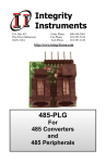
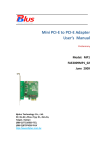
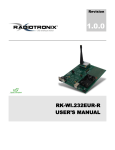
User Manual REMOTE PANEL FOR INVERTER / CHARGER Version: 1.0 Product Overview Communication port and power input: Power input of remote panel. Signal input: Signal input to remote panel. Communication port: Connection to PC. Power switch: Main switch of remote panel. External power input: It’s necessary to have external +5VDC power source when using inverter without dry contact. On/Off switch for external power input. Interface: Remote panel display, operation buttons and indicators. Unpacking and Inspection Before installation, please inspect the unit. Be sure that nothing inside the package is damaged. You should have received the following items inside of package: Remote panel x 1 User manual x 1 RJ45 communication cable x 1 RJ11 cable x 1 Installation Step 1: Drill two holes in the marked locations with two screws. Place the box on the surface and align the mounting holes with the two screws. Then, check if the remote panel is firmly secured. 60.00 mm Ø 5-Ø 9 Note: Installation to the wall should be implemented with the proper screws. Refer chart for recommended spec of screws. M3 Step 2: Before wiring connection, please modify jumper setting of JP1 and JP2 in communication board of the inverter as below. 1 JP1 3 1 JP1 3 1 JP2 3 1 JP2 3 Default communication board setting in inverter Modify setting in communication board when using remote panel Step 3: If the inverter is not bundled with dry contact, please follow below diagram 1 for wiring connection. If the inverter is bundled with dry contact, please follow below diagram 2 for wiring connection. Use a RJ45 to RS232 cable bundled with inverter to connect communication port to PC. If the inverter is not bundled with dry contact, it’s necessary to use an external +5V USB adapter to provide power for remote panel. Step 4: Connect remote panel to inverter with a 6-m RJ45 communication cable and a 6-m RJ11 cable (only available for the inverter with dry contact) as below diagrams. On/off power Switch Necessary External +5V power input Remote Switch (useless) Communication port to PC RJ45 Communication port to remote unit Diagram 1: Wiring diagram for inverter without dry contact On/off power Switch Optional external power input Remote Switch Communication port to PC Remote Switch Signal Communication port and remote +12V power input Diagram 2: Wiring diagram for inverter with dry contact Operation After main switch() and external power input switch(,only available for inverter without dry contact) are powered on, users can monitor and control the inverter from a distance with the remote panel. Besides, users also can monitor and control the inverter with PC software via communication port. The AC output of the inverter can be powered on/off by remote panel. For the interface operation, please refer to the inverter manual.