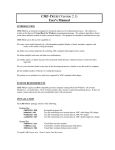
1
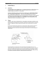
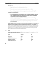
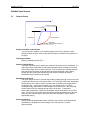
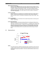
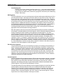
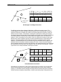
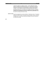
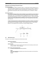
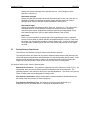
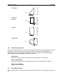
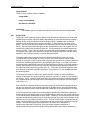
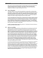
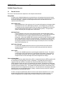
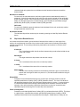
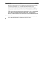
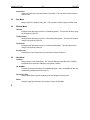
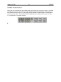
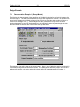
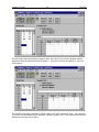
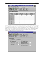
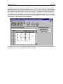
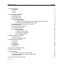
October 18, 1996
i
1. GOLDNAIL BASICS
1.1 Installation
1.2 Theory
1.3 Units
IP3-1253
1
1
1
2
2. GOLDNAIL INPUT SCREENS
2.1 General Screen
2.2 Geometry Screen
2.3 Soils Data Screen
2.4 Safety Factor Screen
2.4.1 Analysis Mode
2.4.2 SLD - Service Load Design (Factor of Safety and Strength Factors)
2.4.3 LRFD Load and Resistance Factor Design
2.5 Piezometric and Surcharge Pressures Screen
2.6 Nails Data Screen
2.7 Facing Pressure Data Screen
2.8 View Geometry Screen
2.9 Run Analysis Screen
2.9.1 Design Mode
2.9.2 Factor of Safety Mode
2.9.3 Nail Service Load Mode
2.9.4 Soil Strength Models
3
3
4
7
8
8
8
8
10
10
11
12
12
13
14
14
15
3. GOLDNAIL OUTPUT SCREENS
3.1 Results Screen
3.2 Slip Surface Results Screen
16
16
17
4. GOLDNAIL MENU SYSTEM
4.1 File Menu
4.2 Edit Menu
4.3 Run Menu
4.4 Window Menu
4.5 Help Menu
19
19
19
20
20
20
5. GOLDNAIL TOOLBAR BUTTONS
21
6. GOLDNAIL FILE SYSTEM
22
7. DESIGN EXAMPLE
7.1 Demonstration Example 1 (Design Mode)
7.2 Demonstration Example 2 (Factor of Safety Mode)
7.3 Non-Planar Walls
23
23
30
33
8. GOLDNAIL TECHNICAL SUPPORT
34
NAILMANU.DOC
October 18, 1996
1.
GoldNail Basics
1.1
Installation
1
IP3-1253
To install GoldNail, put the installation disk in your disk drive and then run SETUP.EXE (you will
find SETUP.EXE on the installation disk). You will be prompted to select a directory for
GoldNail installation (the default is C:\GOLDNAIL).
As with most Windows programs, some files will be copied to your C:\WINDOWS\SYSTEM (or
equivalent) directory during installation. Some users will already have some of these files in
their C:\WINDOWS\SYSTEM directory. If this is the case SETUP.EXE may generate a
message saying that a particular file cannot be copied because it is already in use (this happens
most commonly with the files DDEML.DLL and COMMDLG.DLL will warn you that it cannot
copy a file because the file is already in use. If this happens, click the IGNORE button and
GoldNail should install correctly despite the warning.
1.2
Theory
GoldNail is a slip-surface, limiting-equilibrium, slope-stability model based on satisfying overall
limiting equilibrium (translational and rotational) of individual free bodies defined by circular slip
surfaces. GoldNail can analyze slopes with and without soil nail reinforcement or structural
facing.
For each nail intersecting the slip surface, the reinforcement support provided by that nail is
defined by the nail tension distribution that is characterized by the factored nail pullout
resistance, the factored nail tendon tensile strength, and the factored nail head strength (see
Figure below).
As illustrated above, the tensile force in the nail varies along the length of the nail. The
reinforcement support provided is thus a function of where a particular slip surface intersects a
given nail. The effect of the reinforcement is to improve stability by (a) increasing the normal
force and hence the shear resistance along the slip surface in frictional soils; and (b) reducing
the driving force along the slip surface in both frictional and cohesive soils.
October 18, 1996
2
IP3-1253
Unknowns are:
−
Magnitude of normal force N (along the slip surface)
−
Distribution of normal stress (or force) along the slip surface N = N(l)
−
Factor of safety relating the soil shear strength to the normal stress S = f(N) / FS
The solution proceeds iteratively:
−
For an assumed normal stress distribution N = N(l), GoldNail solves for the magnitude
of the normal force and the factor of safety on soil strength, using the two equations
(horizontal and vertical) of translational equilibrium.
−
GoldNail checks for moment equilibrium. If resisting moments equal disturbing
moments, solution is obtained.
If moments do not balance, GoldNail modifies the normal stress distribution to increase
or decrease the resisting moment, as required, and repeat the process until moment
balance is achieved.
−
GoldNail can also reverse this process to solve for the required nail pattern (nail lengths and nail
strengths) if the user specifies a minimum soil strength factor of safety (i.e., total required nail
reinforcing force replaces the soil factor of safety as one of the unknowns). For each slip
surface analyzed, GoldNail calculates the minimum required nail lengths and nail tendon tensile
strengths, and also checks that the specified nail head strengths are adequate. If specified nail
head strengths are not sufficient to achieve the minimum specified factor of safety, GoldNail
also calculates the minimum nail head strength required.
1.3
Units
Any set of consistent units can be used. Below are two examples of an acceptable set of units,
one in English units and the other in SI.
2.
Input
English
SI
Unit Weight
Soil Cohesion
Nail Tendon Head Strength
Nail Pullout Resistance
Surcharge Pressures
All dimensions of length
lbf/ft3
lbf/ft2
lbf
lbf/ft
lbf/ft2
ft
kN/m3
kN/m2
kN
kN/m
kN/m2
m
October 18, 1996
3
IP3-1253
GoldNail Input Screens
2.1
General Screen
x
X-search limit (right)
X-search limit (left)
Base Depth
Trial Slip Surface
Minimum base exit angle, α
y
Analysis with Nails / without Nails
You can choose to analyze a soil nail wall (analysis with nails) or perform a slopestability analysis (analysis without nails) with the option to consider facing pressure on
the slope.
Unit Weight of Water
Specify in appropriate units (F/L³).
Number of Slip Surfaces
This option allows the user to specify the number of slip surfaces to be considered. If a
single slip surface is specified, the slip surface will approximate a straight line surface
from the base depth to the X search limit (left). This is analogous to a wedge analysis.
Note that the actual number of slip surfaces reported as analyzed is often slightly
smaller than the number specified because the results of attempts to analyze
inadmissible slip surfaces are not reported.
Base Depth for Analysis
This option allows the user to consider slip surfaces passing through a point on the wall
or slope other than the toe of the wall or slope. The critical slip surface will usually pass
through the toe of the wall or slope, but where there are significant heterogeneities in
the problem (e.g., weak layers of material, very non-uniform and/or very heavy
surcharge loading, upper nails of limited length to avoid utilities, etc.), the critical slip
surface might not be one passing through the toe of the wall. To analyze an
intermediate configuration, specify an intermediate vertical depth below top of wall or
slope. For the more usual case of the slip surface passing through the toe of the wall,
enter either the vertical height of the wall or leave this field blank. Specify depth in
appropriate units (L).
Seismic Coefficient
Specify the design pseudostatic seismic coefficient (as a fraction of the gravitational
acceleration) to be applied to the self weight of the soil materials. Units are
(Dimensionless).
October 18, 1996
4
IP3-1253
Minimum Base Exit Angle, α
Specify the minimum allowable base exit angle (measured positive upwards from the
horizontal X axis) at which the slip surface exits the base of the wall or slope. An angle
of negative 10 degrees will generally be suitable. If the output indicates that deepseated slip surfaces require nail support or are providing the critical (minimum) factors
of safety, then the minimum exit angle should be lowered to negative 20 degrees or
less. Units are (Degrees).
X Search Limit (left)
Specify the minimum X-coordinate for the considered slip surfaces to exit the ground
surface. If this point is specified to the left of the top of wall or slope, GoldNail will
assume that the minimum X-coordinate corresponds to the top of wall or slope. Units
are (L).
X Search Limit (right)
Specify the maximum X-coordinate for the considered slip surfaces to exit the ground
surface. Units are (L).
# of X search Exit Points
Specify the number of exit points (including X Search Limit (left) and X Search Limit
(right) to be considered in the slip surface analysis. If 1 is specified only X Search Limit
(left) will be used as an exit point. In general, for soil nail wall design, the number of Xsearch exit points should be equal to the square root of the specified number of slip
surfaces to be analyzed (e.g. specify 10 exit points if 100 slip surfaces are specified).
GoldNail will automatically select the exit points between the left and right X search
limits.
Geometry Screen
0
Horizontal Distance
20
40
0
10
Depth
2.2
20
30
40
Wall Segment
Surface Segment
Internal Segment
Nodes
Nodes
The problem geometry is defined by specifying nodes to describe the limits of the wall
or slope, the ground surface, and any internal material property (soil strength, soil unit
weight, pullout resistance) boundaries. Each node must be defined in terms of its X,Y
coordinates.
October 18, 1996
5
IP3-1253
Coordinate System
GoldNail uses a fourth quadrant coordinate system (i.e., Y axis positive downwards and
X axis positive to the right. In addition, the wall or slope must face to the left (see above
diagram) with the retained soil located to the right (positive X direction) of the wall facing
or slope. Units are (L).
Wall Segments
The wall is defined by one or more wall segments, with each wall segment defined by two of the
previously defined nodes. Wall segments must be defined in order from the base of the wall to
the top of the wall. Wall segments must be non-vertical and battered into the slope. Therefore,
vertical walls must be approximated by a wall with a small batter. Note that only linear walls can
be considered and even if the user specifies a series of wall segments that do not comprise a
straight wall face, GoldNail will adjust the coordinates of the segment nodes so that they all lie
on a straight line between the toe and the top of the wall. For benched walls, overall stability is
therefore assessed with an equivalent battered facing. The user also has the option of
evaluating separate benches as individual walls, possibly with overlying benches modeled as
appropriate vertical and horizontal surcharge pressures.
Each wall segment must also have an associated material-property ID number to identify the
soil strength / unit weight adjacent to that wall segment, and an associated material-property ID
number to identify the pullout resistance value adjacent to that wall segment. The same
material property ID number can be used to define both the soil strength / unit weight and the
pullout resistance properties (see Soils Screen), or the two can be considered separately i.e., a
material property ID number can define either soil properties (strength, unit weight), pullout
resistance, or both. For example, if material type number 6 is entered in the “Soil” column of a
particular segment, then the soil strength and unit weight of material 6 will define the properties
of the soil adjacent to that segment. Similarly, if material-property ID number 4 is identified in
the "Pullout Resistance" column, then the pullout resistance of material 4 will define the pullout
resistance of the material adjacent to that wall segment.
Ground Surface Segments
The ground surface profile can have essentially any shape (no overhangs) and is defined by a
series of segments starting at the top of the wall and extending to beyond the X Search Limit
(right). The segments must be specified in order of increasing X coordinates, starting with the
segment connected to the top of the wall. There must be no overhangs or vertical lines i.e., the
X coordinates of the nodes on the surface should increase from left to right. As with the wall
segments, each surface segment must have an associated material-property ID number that
references a specific soil strength/unit weight identified in the Soils Screen. Pullout resistance
values are not required for surface segments.
Internal Segments
Internal segments define boundaries between different material properties (strength, unit weight,
pullout resistances, or both) within the body of the soil mass. Since each internal segment will
have material on both sides (above and below) of the segment (unlike the wall or surface
segments), the following convention is used to identify which material is associated with the
internal segment in the Soil and Pullout Resistance columns.
The material-property ID number defining the soil strength/unit weight to be associated with the
internal segment, should be that which refers to the material located below the segment.
Therefore, if soil strength/unit weight properties corresponding to material 4 occur above the
internal segment, and soil properties corresponding to material 7 occur below the segment,
material number 7 should be identified in the “Soil” column for that internal segment. See the
Figure below for a visual presentation of this sign convention.
October 18, 1996
6
IP3-1253
4
3
Wall
Segment
Node 1
Node 2
Soil
ID No.
1
2
1
2
2
3
7
4
Internal
Segment
Node 1
Node 2
Soil
ID No.
1
2
5
7
4
2
5
7
1
Pullout
Res. ID No.
Pullout
Res. ID No.
Internal Segment
Boundary 1
Soil Strength / Unit Weight Convention
For defining internal pullout resistance distributions, a different convention is used. The
material-property ID number defining the pullout resistance to be associated with an internal
segment is that which is located on the side of the segment opposite to the side on which the
head of the nail is located. This definition is analogous to that used for defining the strength /
unit weight property associated with internal segments except that a line oriented in the direction
of the nails (instead of a vertical line) is used to define the regions "above" and "below" the
segment. Hence, proceeding from the head of a nail, the initial pullout resistance value is that
defined by the pullout resistance property ID number associated with the corresponding wall
segment. The pullout resistance value along the nail is then unchanged until an internal
segment is encountered by the nail, at which time the pullout resistance value changes to that
associated with the new pullout resistance property ID number. Hence the internal segment
pullout resistance property ID number is that referring to the material that will be encountered as
the nail passes from the wall side of the segment to the non-wall side of the segment. See the
Figure below for a visual presentation of this sign convention.
4
3
1
Nail
Orientation
Wall
Segment
Node 1
Node 2
1
2
1
2
2
3
Internal
Segment
Node 1
Node 2
1
2
5
Soil
ID No.
Pullout
Res. ID No.
2
1
2
2
1
5
Pullout Resistance
Boundary
Soil
ID No.
Pullout
Res. ID No.
1
Pullout Resistance Convention
Since different conventions are used to specify which property ID number is to be associated
with an internal segment for the strength/unit weight property and for the pullout resistance
property, it is advisable to define strength/unit weight internal interfaces and pullout resistance
internal interfaces completely independently, except for particularly simple configurations such
October 18, 1996
7
IP3-1253
as horizontally layered soils. An internal interface with a material-property ID number only in the
“Soil” column will be recognized as a strength/unit weight internal interface only, and the pullout
resistance will not change across the interface. Conversely, if a material property ID number is
given only in the “pullout resistance” column, the internal segment will not comprise an internal
interface with respect to the material strength/unit weight property. See the Figure below for a
visual presentation of the overall input data process.
4
7
3
3
Wall
Segment
Node 1
Node 2
1
2
1
2
2
3
2
1
Surface
Segment
Node 1
Node 2
Soil
ID No.
1
3
4
1
Internal
Segment
Node 1
Node 2
Soil
ID No.
1
2
2
6
5
7
Material
ID No.
c
φ
0
5
30
35
1
Soil
Pullout
ID No. Res. ID No.
3
3
2
4
2
1
6
5
Boundary separating
section into two soil
strength / unit weight
zones [ 1 and 2 ]
Boundary separating
section into two
Pullout Resistance
zones [ 3 and 4 ]
1
2
3
4
2.3
Pullout
Res. ID No.
2
4
Unit
Ultimate Pullout
Weight Resistance Value
18
20
40
60
Soils Data Screen
The soil and pullout resistance properties associated with wall segments, surface segments, and
internal segments are defined by the material-property ID number entered on the geometry screens.
The material type may describe only strength/unit weight, pullout resistance, or both.
For each material-property ID number describe the following material properties:
soil cohesion (c) - Ultimate cohesion in units of stress (F/L²)
soil friction angle (φ) - Ultimate friction angle in degrees
soil unit weight - Unit weight in units of (F/L³)
nail pullout resistance - Ultimate pullout resistance in units of force per unit length of nail (F/L).
Soil input parameters should be selected by experienced geotechnical engineers. For practical
design purposes, the designer should be very cautious about taking credit for significant soil
cohesive strength components, as this can result in the possibility of significantly
underestimating the amount of soil-nail reinforcement required. (Note: Another approach for
addressing the problem of significant soil cohesion at low normal stresses is to treat the upper
soil as a vertical surcharge loading down to the depth of estimated tension cracking). Strength
October 18, 1996
8
IP3-1253
parameters should consider both drained and undrained loading conditions, depending on the
nature of the soil being reinforced.
2.4
Safety Factor Screen
2.4.1
Analysis Mode
Two options are available. Service Load Design (SLD) uses unfactored loads and
applies partial factors of safety to the soil strength and strength factors to each of the
structural resisting elements (nail tendon tensile strength, nail pullout resistance, and
nail head strength). Load and Resistance Factor Design (LRFD) applies load factors to
the applied loads and resistance factors to each of the resisting elements.
2.4.2
SLD - Service Load Design (Factor of Safety and Strength Factors)
Soil Strength
For a linear c/φ material strength, individual partial factors of safety can be
applied to the cohesion and friction components. For a bilinear (non-linear)
material strength specification, only a single factor of safety is required. This is
taken as the factor of safety specified in the friction input box.
Nail Tendon Strength
Strength factor applied to the nominal nail tendon tensile (yield) strength. Must
be less than or equal to 1.0.
Nail Head Strength
Strength factor applied to the nominal nail head strength. Must be less than or
equal to 1.0.
Nail Pullout Resistance
Strength factor applied to the estimated ultimate nail pullout resistance. Must be
less than or equal to 1.0.
2.4.3
LRFD Load and Resistance Factor Design
LRFD-Resistance Factors
Resistance factors are typically less than unity and are used to define factored
strengths by multiplying the nominal/ultimate strengths by the appropriate resistance
factors. Resistance factors are defined for each of the resisting elements considered
above.
LRFD Load Factors
Unit Weight of Water
Load factor applied to unit weight of water, and hence to the water pressures
derived therefrom.
Unit Weight of Soil
Load factor applied to the unit weight of the soils retained by and reinforced with
the soil nails.
Surcharge Pressures
October 18, 1996
9
IP3-1253
Load factor applied to surcharge pressures. Typical LRFD codes specify
different load factors for different load types (e.g., dead weight of structural
components, dead weight of wearing surfaces, live loads of various types).
Therefore, for a surcharge composed of different load types with different
associated load factors, it is necessary with GoldNail to develop a composite
load factor for the specified surcharge. One approach is to simply factor the
surcharge load combinations in accordance with the code specifications, and
then set the surcharge load factor to unity.
Seismic Loads
Load factor applied to the seismic coefficient. Usually set to unity. The seismic
loading in the LRFD mode is calculated as the pseudostatic seismic coefficient
multiplied by the unfactored soil material self weight, and not by the factored
soil material self weight.
2.5
October 18, 1996
10
IP3-1253
Piezometric and Surcharge Pressures Screen
Piezometric Surface
It is not necessary to define a piezometric surface. If no piezometric surface is defined, then no
water pressures will be generated for any slip surfaces considered in the analysis. Otherwise, a
piezometric surface is defined by a series of sequential points, proceeding from left to right i.e.,
in the direction of the positive X axis. Each point is defined by its X,Y coordinates. Units are
(L).
Surcharge Pressures
Any vertical or horizontal surcharge pressure distribution may be applied to the upper surface of
the reinforced soil, starting at the top of the wall and proceeding from left to right in the direction
of the positive X axis. The surcharge pressures are applied as a series of uniform vertical and
horizontal surcharge pressures, from one X coordinate value to the next. The first zone extends
from the top of the wall to the specified X coordinate on the first line of input, the second zone
extends from the X coordinate on the first line of input to the X coordinate on the second line of
input, and so on.
Vertical surcharge pressures are positive downwards (in the positive Y direction or the direction
of gravity) and horizontal (shear) surcharge pressures are positive when directed towards the
wall or slope face (in the negative X direction). Units for pressure are (F/L²). See the Figure
below for a visual example of the convention for entering surcharge pressures.
2.6
Nails Data Screen
This screen is only available if analysis with nails has been selected.
Nail Horizontal Spacing
Specify the horizontal nail spacing in units of length (L)
Nail Declination
Specify the angle (measured positive downwards from the horizontal) at which the soil
nails are declined. Units are (Degrees).
Nail Locations and Properties Table
For each nail row, specify the following properties:
Depth
Specify the vertical distance below the top of the wall to the location of the head of the
nail in units of length (L).
Length
October 18, 1996
11
IP3-1253
Specify the inclined nail length of the specified nail row. All nail lengths must be
specified. Units are (L).
Nail tendon strength
Specify the yield load (nominal nail tendon tensile strength) for each nail. Units are (F).
GoldNail will modify the specified nail tendon tensile strength by the Nail Tendon
Strength Factor (SLD) or the Nail Tendon Resistance Factor (LRFD).
Nail Head Strength
Specify the nominal nail head strength for each nail. Units are (F). This value will be
calculated based on a consideration of facing flexure/shear and other nail-facing
connector failure modes. GoldNail will modify the specified nail head strength by the
Nail Head Strength Factor (SLD) or Nail Head Resistance Factor (LRFD).
Nail Fixed?
Enter a y (case insensitive) to specify that a nail length/strength is fixed. Otherwise
leave the column blank to indicate that the nail length/strength is not fixed. There must
be at least one non-fixed nail to analyze a wall in design mode. In factor-of-safety and
nail-loads mode, GoldNail ignores the Nail Fixed column and assumes all nail lengths
are fixed.
2.7
Facing Pressure Data Screen
This screen is only available if analysis without nails has been selected.
The analyses without nails option can be used to calculate earth pressure loads (assuming any
of the earth pressure distributions described below) for unreinforced walls (design mode). It can
also be used to calculate the factor of safety of an unreinforced wall or slope by setting the
magnitude of the face pressure equal to zero and using the factor of safety mode.
For analyses without nails, enter the following data:
Maximum Face Pressure - The maximum magnitude of the face pressure in Units of (F/L²). As
noted below, there are several different pressure distributions that can be employed. The
specified pressure is the maximum value for the specified distribution. This value is only used in
Factor of Safety mode and is disregarded in Design mode.
Face Pressure Declination- Specify the declination (measured positive downwards from the
horizontal) of the face pressure in Units of (degrees).
Face Pressure Distribution Type- The shape of the face pressure distribution (e.g.
trapezoidal, uniform, truncated uniform, or triangular) as illustrated below:
October 18, 1996
12
IP3-1253
Triangular
H
pmax
Truncated
Uniform
pmax
H
H/4
Uniform
H
pmax
Trapezoidal
H/4
pmax
H
H/4
2.8
View Geometry Screen
The view icons permit the user to view either the original problem geometry, for the purpose of checking
input data, or to view the problem geometry together with the locations of the nails (designed or
specified, depending on the analysis mode) and the critical slip surfaces. The critical slip surfaces
shown depend on the Analysis Mode in the following manner:
Design Mode:
Shows the critical slip surface that controls the maximum length of nail required.
Factor of Safety Mode:
Shows the critical slip surface corresponding to the minimum calculated factor of safety.
Nail Service Load Mode:
Shows no slip surface plots.
2.9
Run Analysis Screen
The run-analysis screen is accessed by pressing the Run Analysis button or selecting Run on the menu
bar.
October 18, 1996
13
IP3-1253
Analysis Mode
There are three analysis modes in GoldNail.
Design Mode
Factor of Safety Mode
Nail Service Load Mode
Soil Models
The GoldNail user can choose to use either a linear or bi-linear soil strength model.
2.9.1
Design Mode
This mode is most commonly used for design of soil nail walls and allows the user to have the
GoldNail program design a final nail pattern that satisfies all of the specified factors of safety /
strength factors (SLD) or load and resistance factors (LRFD), consistent with the material
properties (soils and reinforcement system) specified. To start, the user must input a trial
design. The user must specify the depths of the nail head rows below the top of the wall (see
below). The nominal nail head strength must also be specified for each nail, together with the
nominal nail tendon tensile strength for each nail. An initial estimate of each nail length must
also be provided. There is also an option to fix certain nail lengths/strengths in design mode for example, if the upper row of nails will be shorter due to utility interference, then this can be
specified in the Fixed Nail? Column on the nail data input screen.
The Design Mode output consists of minimum required nail lengths for each row of nails
(consistent with any fixed length nail rows), minimum required nominal nail tendon tensile
strength for each row of nails (consistent with any fixed strength nail rows), and also checks the
nominal nail head strengths specified on the Nail Data Input Screen. If the input nominal nail
head strengths are inadequate to achieve the specified factors of safety (or load and resistance
factors), then GoldNail will calculate new minimum required nail head strengths (indicated by
the output Nail Head Factor being greater than 1.0.). If the input nail head strengths are more
than adequate (indicated by the Nail Head Factor being equal to 1.0), then GoldNail will retain
the values specified.
The required nail lengths to achieve the specified factors of safety (or load and resistance
factors) will be output as a simple multiple (greater than, less than, or equal to 1.0) of the input
nail lengths. That is, except for fixed length nails, the relative nail lengths remain constant and
are a constant factor (the nail length factor of the Results Screen) times the input nail lengths
(see Section 3.1).
Also note that the calculated minimum required nominal nail tendon tensile strengths for each
nail row can exceed the value originally specified on the Nails Screen, and this indicates that
that the specified nail tendon tensile strength was inadequate for the required factors of safety.
If the final required nail lengths or nail head strengths calculated by GoldNail are significantly
different from the trial design entered on the Nail Data Input Screen, then the problem should be
re-run with adjusted initial estimates of these values. Similarly, if the required nail tendon tensile
strengths are significantly greater than the originally specified nail tendon tensile strength on the
Nails Screen, then the analysis should be re-run. The nail head strengths, nail length, and nail
tendon tensile strengths are used to calculate the total nail support force required for each slip
surface. The total nail support required depends to an extent on the distribution of
reinforcement loads within the ground. If the final design suggests a distribution of
reinforcement within the ground that is significantly different from that initially estimated (e.g.,
October 18, 1996
14
IP3-1253
nails are twice as long as originally specified, nail head strengths are fifty percent higher than
originally estimated), then the calculated total nail support for each slip surface will be
somewhat inconsistent with the final design. With experience, the user will identify what
changes (in nail length, etc.) require the problem to be re-run.
2.9.2
Factor of Safety Mode
This option enables the user to calculate the global factor of safety (SLD) or resistance/load
ratio (LRFD) for a given nail pattern, compatible with the specified soil strength partial factors of
safety (SLD) or resistance factors (LRFD), the nominal nail tendon tensile strengths, nominal
nail head strengths, and soil-nail ultimate pullout resistances, and their respective associated
strength factors (SLD) or resistance factors (LRFD). This option is useful for back analysis of
existing soil nail walls or designs developed using other design methods.
The calculated global factor of safety (SLD) or resistance/load ratio (LRFD) is applied to the soil
strength, over and above the soil strength partial factors of safety / resistance factors specified
on the safety factor screen (i.e. the factors of safety are cumulative). In SLD for example, the
actual overall factor of safety (applied to soil strength) will be the product of the specified soil
strength partial factors of safety and the calculated global factor of safety. It is recommended
therefore that, for SLD, the input soil strength partial factors of safety be set to 1.0 on the safety
factor screen when using factor of safety mode.
In LRFD, a calculated resistance/load ratio greater than 1.0 indicates that factored resistances
exceed factored loads, and vice versa.
2.9.3
Nail Service Load Mode
Whereas the Design Mode and the Factor of Safety Mode can be used with both the SLD and
LRFD approaches, the Nail Service Load Mode can be used only with the SLD method (i.e.,
load factors cannot be used). The Nail Service Load Mode provides an estimate of the nail
service loads rather than identifying the required nail tendon tensile strengths, as for the Design
Mode. If it is assumed that service loads developed in the nails are approximately consistent
with the mobilization of the full soil strength (which is a reasonable assumption based on nail
service load and wall deflection measurements from instrumented, in-service, soil nail walls),
then the soil strength factors of safety should be set to unity when using this mode. GoldNail
will then calculate a distribution of mobilized nail loads that is consistent with the mobilization of
the full soil strength. (Note: Inspection of monitored nail loads from in-service walls, together
with the soil strength properties estimated by the wall designers, suggests that mean nail
service loads can be approximately estimated by assuming a soil factor of safety of slightly
greater than unity.). It is suggested that strength factors for the structural elements (for nail
tendon tensile strength, nail head strengths, and ultimate pullout resistance) be set at their usual
values when estimating nail service loads.
It must also be noted that the actual in-service loads can be truly assessed only by models that
account for the actual soil-nail-facing load-deformation interactions. GoldNail is a limiting
equilibrium model and does not therefore incorporate the deformational response of the system.
The nail load distributions provided by GoldNail merely reflect the pattern of load distribution
among the nails that is intrinsically incorporated into the limiting equilibrium model (see Theory
Screen). It is considered that this nail load distribution provides a reasonable representation of
the in-service case, based upon inspection of the results from in-service nail load monitoring,
provided that the user follows FHWA recommendations (FHWA Design Manual for Soil Nail
Walls) for the specified nail length pattern.
October 18, 1996
15
IP3-1253
The Nail Service Load Mode will not, in general, be used by the soil nail wall designer. It is
intended primarily to allow prediction of nail service loads for comparison to service loads
measured in instrumented in-service walls (e.g. as part of research programs).
2.9.4
Soil Strength Models
Soil Models
Shear Strength
40
30
20
Linear
10
Bi-linear
0
0
10
20
30
40
Normal Stress
50
Linear
The linear Mohr-Coulomb strength envelope is used.
Bi-linear
In the event that the linear Mohr-Coulomb strength relation is considered to
overestimate the shear strength at low normal stress values (i.e., the strength relation is
truly non-linear and curves to zero strength at zero normal stress), this option
approximates the curvilinear strength relation by a bi-linear model as shown on the
associated Figure. The slope of the initial leg of the bi-linear strength relation is defined
by tan-¹(cos(φ)/(1-sin(φ)), where “φ” is the material friction angle. The second leg of the
bilinear model is the original Mohr-Coulomb strength line. These two relations converge
as the cohesion intercept tends to zero. Please note that Golder has not developed an
independent hand calculation to verify the accuracy of bi-linear soil model option
calculations.
For practical design purposes, the designer should be very cautious about taking credit
for significant soil cohesive strength components, as this can result in the possibility of
significantly underestimating the amount of soil-nail reinforcement required. (Note:
Another approach for addressing the problem of significant soil cohesion at low normal
stresses is to treat the upper soil as a vertical surcharge loading down to the depth of
estimated tension cracking).
3.
October 18, 1996
16
IP3-1253
GoldNail Output Screens
3.1
Results Screen
The format of the Results Screen depends on the analysis mode selected.
Design Mode
In design mode, GoldNail displays the required minimum nail lengths and nominal nail tendon
tensile strengths together with the associated slip surface numbers that controlled the required
nail tendon strengths. In addition, the nail length factor and the nail head factor are also
reported as described below.
Nail Length Factor
The nail length factor is the maximum ratio of required nail lengths to the lengths initially
specified by the user on the Nail Data Input Screen. A nail length factor greater than
1.0 indicates that the originally specified trial nail lengths are inadequate to provide the
specified partial safety factors (SLD) or resistance factors (LRFD). The slip surface
number controlling the nail length factor is also shown.
Nail Head Factor
The nail head factor is the ratio of the required nominal nail head strengths to those
initially specified by the user on the Nails Data Input Screen. A nail head factor greater
than 1.0 indicates that the originally specified nominal nail head strengths are
inadequate. In this case GoldNail will increase the specified nominal nail head strength
by the nail head factor to achieve the required design. The designer must then modify
the nail head connection design to achieve the required nominal nail head strength. If
the originally specified nominal nail head strengths are adequate, then the nail head
factor will be reported as 1.0.
Nail Tendon Strength
For each nail, GoldNail reports the maximum required nominal nail tendon tensile
strength calculated for the nail, and the slip surface that generated that maximum
required strength.
Nail Lengths
For each nail, GoldNail reports the required length calculated for the nail. The pattern
of nail lengths is kept proportional to the specified trial input pattern of nail lengths (i.e.
the nail lengths are equal to the input length multiplied by the nail length factor). The
exception to this are the fixed length nails, whose lengths do not change.
Factor of Safety Mode
The computed minimum global safety factor (SLD) or resistance/load ratio (LRFD), together with
the associated critical slip surface number, is displayed. The global safety factor (SLD) or
resistance/load ratio (LRFD) is calculated after all specified SLD partial factors of safety or
LRFD resistance factors have been incorporated into the analysis. Global factors of safety can
be calculated in a variety of ways (e.g. ratio of resisting forces to driving forces, ratio of resisting
moments to driving moments, etc.). For GoldNail, the global safety factor is determined as the
factor by which the soil strength can be reduced (i.e. over and above the soil strength reductions
specified by the soil strength partial factors of safety / resistance factors) to achieve a state of
limiting equilibrium along the slip surface.
For SLD, the input soil partial safety factors for friction and cohesion should be set to 1.0 and
the calculated global factor of safety must exceed the design factor of safety required. For
LRFD, the appropriate soil strength resistance factors should be input and a calculated
October 18, 1996
17
IP3-1253
resistance/load ratio greater than one indicates that the factored resistances exceed the
factored loads.
Nail Service Load Mode
For each nail, the calculated service nail load, together with the associated slip surface, is
presented. It should be noted that for this mode, the nail service load and not the nail tendon
tensile strength is output. Where nail tendon tensile strength is provided (e.g., for the Design
Mode), the strength output is the nominal strength, which includes the nail tendon strength
partial safety factors (SLD) / resistance factors (LRFD) specified.
Nail Loads
For each nail, GoldNail reports the maximum load calculated for the nail, and the slip surface
that generated the maximum load.
Slip Surface Results
The individual slip surface results may be viewed by pressing the View Slip Surface Results
button.
3.2
Slip Surface Results Screen
In all cases the surface numbers, ground surface X-intercept of the surface, toe exit angle of the
surface, the coordinates of the center of the circular surface, and the ratio of resisting to disturbing
moment are presented. The remaining information presented for each surface is a function of the
analysis mode.
X-intercept
The X-coordinate at which the slip surface intersects the ground surface behind the top
of the wall or slope.
Base Angle
The angle at which the slip surface exits the wall or slope.
X-Center
The X-coordinate of the center of the circular slip surface.
Y-Center
The Y-coordinate of the center of the circular slip surface.
Moment Ratio
The ratio of the resisting moments to the disturbing moments is given to check that the
solution has converged to within one percent i.e., the ratio should lie within the range of
0.99 to 1.01.
Design Mode
Presents the total calculated reinforcing force required per unit length of wall to meet the
specified partial factors of safety (SLD) / (LRFD) resistance factors. The sum of the factored
nail strengths (determined from the nail support diagram shown in Section 1.1 as the minimum
of: factored nail tendon tensile strength; factored nail pullout resistance; factored nail head
strength; of the nails intersecting a particular slip surface must equal or exceed this total
calculated required reinforcing force for each slip circle considered.
Factor of Safety Mode
Presents the calculated global factor of safety (SLD) or resistance/load ratio (LRFD). This factor
is a global factor, calculated after all other specified SLD partial factors of safety or LRFD
resistance factors have been incorporated into the analysis. Global factors of safety can be
October 18, 1996
18
IP3-1253
calculated in a variety of ways (e.g. ratio of resisting forces to driving forces, ratio of resisting
moments to driving moments, etc.). For GoldNail, the global safety factor (SLD) or
resistance/load ratio (LRFD) is determined as the factor by which the soil strength can be
reduced (i.e. over and above the soil strength reductions specified by the soil strength partial
factors of safety / resistance factors) to achieve a state of limiting equilibrium along the slip
surface.
For SLD mode the input soil partial safety factors should be set to 1.0 and the calculated global
factor of safety must exceed the design factor of safety required. For LRFD mode, the
appropriate soil strength resistance factors should be input and the calculated resistance/load
ratio must exceed 1.0 to ensure that the factored resistances exceed the factored loads.
Nail Service Load Mode
Presents the total calculated reinforcing force per unit width of wall, consistent with the soil
factor of safety specified (usually at or slightly above unity for this mode).
4.
October 18, 1996
19
IP3-1253
GoldNail Menu System
4.1
File Menu
New
Erases the current data file from memory and clears all input screens. This can also be
done using the shortcut key Ctrl+N.
Open
Brings up the File Open dialog to load an existing data file. This can also be done using
the toolbar icons or the shortcut key Ctrl+O.
Save
Saves the file using its current file name. You are not warned if an existing file will be
overwritten. This can also be done using the toolbar icons or the shortcut key Ctrl+S.
Save As
Brings up the File Save As dialog to save the current file with a new name. This can
also be done using the shortcut key Ctrl+A.
Print
Allows the user to print the current input file, output file, or slope/nail geometry.
Printer Setup
Brings up the Printer Setup dialog to allow the user to select a printer or change printer
properties such as page orientation.
Exit
Causes the program to terminate. This can also be done using the toolbar icons or the
shortcut key Alt+F4.
4.2
Edit Menu
Cut
Copies the selected data from the screen, pastes it to the clipboard, and deletes it from
the screen. This can also be done using the toolbar icons or the shortcut key Ctrl+X.
Copy
Copies the selected data from the screen and pastes it to the clipboard. This can also
be done using the toolbar icons or the shortcut key Ctrl+C.
Paste
Copies data from the clipboard and “pastes"it to the screen. This can also be done
using the toolbar icons or the shortcut key Ctrl+V.
Clear
Deletes the selected data from the screen without copying it to the clipboard. This can
also be done using the toolbar icons or the shortcut key Delete.
Delete Rows
Deletes rows at the selected location in the table. This can also be done using the
toolbar icons.
October 18, 1996
20
IP3-1253
Insert Rows
Inserts rows above the selected location in the table. This can also be done using the
toolbar icons.
4.3
Run Menu
Brings up the Run Analysis dialog box. This can also be done using the toolbar icons.
4.4
Window Menu
Cascade
Arranges open data-entry screens in a cascading pattern. This can also be done using
the shortcut key Shift+F5.
Tile Horizontal
Arranges open data-entry screens in a horizontally-tiled pattern. This can also be done
using the shortcut key Shift+F4.
Tile Vertical
Arranges open data-entry screens in a vertically-tiled pattern. This can also be done
using the shortcut key Shift+F3.
Arrange Icons
Arranges the icons of data-entry screens that have been minimized.
4.5
Help Menu
Contacts
Brings up the Contacts dialog box. The Contacts dialog box provides a list of Golder
Associates office locations, addresses, and phone numbers.
On GoldNail
Provides context-specific help on the GoldNail program. Help on GoldNail can also be
accessed by pressing the shortcut key F1.
How to Use Help
Brings up Windows’ Help file explaining how help programs can be used.
About
Presents copyright information and version numbers for GoldNail.
5.
October 18, 1996
21
IP3-1253
GoldNail Toolbar Buttons
Most of the menu functions also have toolbar buttons to allow the user to work more quickly. In general,
the toolbar buttons are similar to those used and should be almost self-explanatory. To find out more
about toolbar functions, press F1 for help when running GoldNail, and select GoldNail Toolbar Buttons
from the Contents menu. The help file will then display a copy of the toolbar that the user can click on
for an explanation of the toolbar functions.
6.
October 18, 1996
22
IP3-1253
GoldNail File System
All GoldNail input and output files are saved in an ASCII text format. You can view the files with
any text file viewer. GoldNail formats the output using extended ASCII line-draw characters and
will look best when your viewer uses a fixed-width font that supports the extended ASCII
characters. Windows-based fixed-width fonts that support extended ASCII line-draw characters
include MSLINEDRAW and IBMPCDOS. Other fixed-width fonts (e.g. COURIER) will work
acceptably, but will substitute odd symbols for the line-draw characters.
Input Files
GoldNail saves input information in ASCII text files with the extension .gni.
Output Files
Design Mode
GoldNail saves Design-Mode output information in ASCII text files with the extension
.gnd.
Factor-of-Safety Mode
GoldNail saves Factor-of-Safety -Mode output information in ASCII text files with the
extension .gnf.
Nail Service Load Mode
GoldNail saves Nail-load-Mode output information in ASCII text files with the extension
.gnl.
7.
October 18, 1996
23
IP3-1253
Design Example
7.1
Demonstration Example 1 (Design Mode)
The following is a demonstration of the application of GoldNail for design of a soil nail wall support for a
9.5 meter-high cut. The wall will be battered at an angle of 10 degrees from vertical. The General Data
screen below indicates that 250 slip surfaces will be considered, and these slip surfaces will have a
minimum toe exit angle of 0o (i.e., horizontal), will exit the ground above the top of the wall at 20
locations between 0.1m and 20m horizontally from the top of wall, and will all pass through the toe of
the wall located at a vertical depth of 9.5m below the top of the wall.
The geometry of the wall is input on the screen below. Nodes 1 and 2 define the wall face, and nodes 2,
3 and 4 define the ground surface above the wall. The wall segment defined by nodes 1 and 2 has the
adjacent soil strength, unit weight and pullout values defined by material property ID number 1.
October 18, 1996
24
IP3-1253
The two surface segments defined by nodes 2 and 3, and 3 and 4, also have the adjacent material
properties defined by material property ID number 1. There are no internal boundaries i.e, the soil is
homogeneous.
The ultimate soil strength is defined by a friction angle of 34o and a cohesion of 5 kPa. The unit weight
is 18 kN/m3 and the ultimate pullout resistance is 60 kN/m length of nail. These material properties are
described on the input screen below.
October 18, 1996
25
IP3-1253
A Service Load Design approach will be used. The required factor of safety (applied to the soil strength)
is 1.35. Allowable nail head loads are determined by applying a nail head strength factor of 0.67 to the
nominal nail head strength. Similarly, allowable nail tendon tensile loads are obtained by applying a nail
tendon strength factor of 0.55 to the nominal nail tendon tensile (yield) strength. Allowable nail pullout
values are taken as 0.5 times the ultimate pullout strength. The required factor of safety and the
respective strength factors are input on the screen below.
October 18, 1996
26
IP3-1253
A trial pattern of nails is input on the screen below. The nominal nail tendon (yield) strength is 200 kN
(#25M Grade 400) and the nominal nail head strength is 117 kN, for each of the nails. Trial nail lengths
are also shown for a trial nail pattern, ranging from 7.7 meters for the three nails in the upper half of the
wall, to progressively shorter nails in the lower half of the wall. The rationale for this type of pattern of
nail lengths is contained in Manual for Design of Soil Nail Walls - FHWA Demonstration Project DP103.
The locations of the nail heads are given in terms of vertical depth below the top of the wall. The nails
will be inclined at 15o below horizontal and the nail horizontal spacing is 1.5 meters. There are no nails
of fixed length. These input data are indicated below.
The design mode is used, in which the trail pattern is checked for consistency with the required factors
of safety previously given, and adjustments made if necessary.
October 18, 1996
27
IP3-1253
The output screens are shown below. The output indicates that the nail lengths specified cannot be
significantly decreased (nor need they be increased) and that maximum nail lengths of 7.7m are
required. The specified nail head strengths are also adequate, as indicated by a Nail Head Factor of
1.0. The maximum required nominal (yield) strength of the tendons is indicated as being about 160 kN,
which is less than the 200 kN specified. If desired, smaller nail tendons could be employed.
October 18, 1996
28
IP3-1253
Typical output data for some of the slip surfaces are shown below, including data for the critical surface
(#156) that controlled the required nail lengths.
October 18, 1996
29
IP3-1253
Note that the slip surface requiring the maximum total reinforcing force (Circle Number 70 above) is not
necessarily the same as the slip surface that controls the maximum nail length required (Circle Number
156 - previous page). It is easily envisaged how a more deep-seated slip surface that required less
reinforcing support will control nail length required to avoid pullout.
A plot of the calculated design nail pattern and the critical slip circle #156 are shown below.
October 18, 1996
30
IP3-1253
Finally, as explained in the Manual for Design of Soil Nail Walls, the design pattern of nail lengths is
developed to ensure that adequate reinforcing steel is placed in the upper part of the wall. It should not
be interpreted that the actual installed nail pattern must conform to the calculated nail length pattern.
For example, in the problem presented above, a uniform nail length pattern of 8 meters might be used,
or alternatively, the upper four rows of nails might be 8 meters long and the lower two rows 6 meters
long, at the designer's discretion.
7.2
Demonstration Example 2 (Factor of Safety Mode)
The same problem as above is considered. All input screens are the same with the exception of the
following: The safety factor screen is modified as shown below, with the partial soil factors of safety set
to 1.0.
October 18, 1996
31
The factor of safety mode is selected, as shown below.
The calculated minimum factor of safety, for the specified nail pattern, is 1.35 as shown below.
IP3-1253
October 18, 1996
32
IP3-1253
Note that the critical circle number for the factor of safety calculations (Circle No. 163) does not
correspond to the critical circle number for the nail length determination in the design mode (Circle No.
156). The reasons for this are:
a) the same circle numbers do not necessarily represent the same circles in the two different
analyses (i.e. Circle 100 may be a deep-seated circle in Design Mode, but could be a
shallow circle in Factor of Safety Mode);
b) each solution proceeds iteratively and convergence "round-off" approximations may result in
slight differences between the Design Mode analysis and the Factor of Safety Mode
analysis.
A plot of the nail pattern and the critical slip surface is given below.
October 18, 1996
7.3
33
IP3-1253
Non-Planar Walls
Although GoldNail is strictly limited to evaluating the stability of planar walls and to considering slip
surfaces that exit the wall at or above the toe of the wall, non-planar walls can be examined (or slip
surfaces exiting below the toe of the wall considered) by using the approach illustrated on the figure
below. The figure shows the soil nail wall a-b. If it is desired to use GoldNail to examine the stability of
slip surfaces exiting at point c, for example, below the base of the wall, this can be achieved by defining
a “dummy” wall, a-c, and treating both the wall a-b and the ground surface b-c, as internal boundaries.
The nail head depths and the nail lengths must be adjusted accordingly in order that the nails are
correctly located with respect to the actual wall a-b, which is simulated as an internal boundary. In
addition, the zone defined by region a-b-c must be modeled as having essentially zero unit weight, zero
strength and zero pullout resistance, although very small values (rather than zero) should be input for
these parameters.
a
b
c
8.
Trial Slip Surface
October 18, 1996
34
IP3-1253
GoldNail Technical Support
THE GoldNail SOFTWARE IS PROVIDED FOR INFORMATION PURPOSES ONLY, AND NO
WARRANTY IS EXPRESSED OR IMPLIED REGARDING ITS ACCURACY, FUNCTIONALITY, OR
APPLICABILITY.
Any permission granted for the use of this program includes the explicit condition that all liabilities and
responsibilities for any results obtained from its use are exclusively those of the individual user or
organization. No responsibility is assumed or implied for user support.
Please report GoldNail bugs to Golder Associates by contacting us at:
Golder Associates Inc.
18300 NE Union Hill Rd. #200
Redmond, WA 98052 USA
Attention: Mr. Joe Hachey
tel: (425) 883-0777
fax: (425) 882-5498
email: [email protected]
We strongly suggest that you report GoldNail bugs by mail, fax, or email. If your problem is an actual,
serious bug in GoldNail, we will attempt to contact you. We will not contact you regarding minor bugs,
but may incorporate fixes for the bugs in future GoldNail versions. We will not generally respond if the
problem is not a bug. If you contact us via telephone and your problem is not a GoldNail bug (e.g. you
did not correctly understand the instructions in the user manual), you will be invoiced for our time spent
helping you at a rate of US$150/hr in minimum half-hour increments (i.e. there is a minimum US$75
charge for a telephone call for anything other than a GoldNail bug - Golder Associates at its sole
discretion will decide whether a problem constitutes a bug).