1
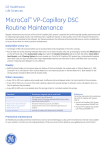
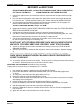
APPENDIX C USER’S MANUAL
RECOVERY and RECYCLING
BEFORE STARTING RECOVERY, ALLOW THE AUTOMOBILE ENGINE TO RUN A FEW MINUTES
WITH THE A/C SYSTEM OFF.
A WARM ENGINE WILL HELP SPEED RECOVERY.
1. Connect blue system hose to the low side port of the A/C system and the red system hose to the high
side port.
2. Make sure the unit is plugged into a grounded 115v outlet and the valves on the recycle tank and the
tank hoses are open. Turn the unit power switch to ON. Selector switch to RECOVER & RECYCLE.
3. Open the valves on the red and blue system hoses and check for pressure on the unit gauges. No
pressure indicates that there is no refrigerant in the A/C system.
DO NOT RECOVER AN EMPTY A/C SYSTEM
4. If gauges show pressure, press the START RECOVERY & RECYCLE button. The START RECOVERY
& RECYCLE IN PROGRESS light will flash.
5. As refrigerant is recovered from the A/C system, the pressure gauges will begin to drop.
6. When the A/C system pressure reaches 6 in-hg of vacuum, the unit will automatically shut down. If the
pressure rises, the unit will restart automatically to recovery any residual refrigerant. This process will
repeat until A/C system has been recovered and remains in a stable vacuum.
7. Once the unit senses that the A/C system has held a stable vacuum for two minutes, any oil removed
from the A/C system will purge into oil discharge cup.
DO NOT SHUT UNIT OFF DURING PRESSURE CHECK AND OIL PURGE PROCESS.
WAIT UNTIL “RECOVERY & RECYCLE IN PROCESS” LIGHT STOPS FLASHING.
8. Remove oil discharge cup and read the amount from the markings on the cup. LITTLE OR NO OIL
REMOVED IS NORMAL.
9. Dispose of recovered oil in accordance with any federal, state or local ordinances. Replace discharge
cup
REPALCE ANY OIL REMOVED WITH PROPER LUBRICANT FOR A/C SYSTEM.
CHECK VEHICLE MANUFACTURERS PUBLISHED SERVICE PROCEDURES FOR
CORRECT LUBRICANT.
10. The recovery & recycle process is now complete. Close the valves on the system hoses and disconnect
from vehicle. Necessary repairs can now be made to the A/C system.
REPLACING THE FILTERCORE (Units with recovery / recycling)
Change Filter core every 20 hours as indicated by unit in a vacuum.
1. Close valves on the hoses or couplings of the RED and BLUE unit hoses.
2. Press START RECOVERY & RECYCLE button and allow unit to run until the LOW gauge rises to
5 to 10 psi.
3. Turn unit power to OFF when the LOW gauge reaches 0 to 5 psi.
4. Loosen the center bolt on the filter shell lid three full turns.
5. Turn the lid counterclockwise until it stops and lift up on the lid. The center bolt may have to be pushed
down slightly prior to turning the lid.
6. Remove th esoring plate. Remove the old filter core and dispose of it properly.
7. Remove the new filter (P/N K16200-SP 2 pack) from the vacuum sealed container and install it
immediately in the filter shell with the cone-shaped end up.
8. Install the spring plate on top of the new core with the spring facing up.
9. Replace the filter shell lid and turn it clockwise until the marks on the side of the lid are alighned with
those on the seal.
10. Tighten the center bolt on the filter shell lid to 10 ft-lbs. Of torque.
Page C-2
Effective
7/2000
APPENDIX C USER’S MANUAL
RECOVERY & RECYCLING INDICATORS
HOURMETER: The hour-meter totals the time the machine has operated in the recovery mode. This allows
tracking of the total accumulated recovery time on the filter. The filter should be changed after every 20 hours.
HIGH PRESSURE INDICATOR: The HIGH PRESSURE indicator will illuminate when the pressure on the
discharge side of the recovery unit exceeds 435 psi. Failure to open the valves on the recycle tank or recycle
tank hoses will cause high-pressure condition to occur.
If the HIGH PRESSURE indicator illuminates:
1. Ensure that the valves on the recycle Tank and tank hoses are fully open to allow refrigerant to flow into
the recycle tank.
2. If valves are open, excess air is probably present in the tank. Turn unit off and allow tank to cool.
3. Turn unit back ON and wait 40 to 60 seconds. The EXCESS AIR indicator
EXCSS AIR INDICATORS
The EXCESS AIR indicator will illuminate and stay on if there is excess air in the recycle tank. Excess air is
detected automatically by the recovery / recycle unit with no need for pressure / temperature comparison by the
operator.
If the EXCESS AIR indicator comes on and does not flash:
1. Properly dispose of any oil in the oil purge cup and reinstall cup in unit
2. Depress the START EXCESS AIR PURGE BUTTON. The air purge process will shut off automatically
once the excess air has been expelled.
The EXCESS AIR indicator can also FLASH to indicate other conditions besides excess air:
ONE FLASH
TWO FLASHES
THREE FLASHES
FOUR FLASHES
ON
ON
ON
ON
OFF ON OFF ON OFF ON OFF
ON OFF ON ON OFF ON ON OFF
ON ON OFF ON ON ON OFF
ON ON ON OFF ON ON ON ON OFF
TANK PROBE NOT CONNECTED
RECOVERY TANK TOO COLD
RECOVERY TANK TOO HOT
TANK FULL INDICATOR
The TANK FULL indicator will illuminate and stay on if the recycle tank becomes 80% full.
If the TANK FULL indicator comes on and does not flash:
1. Check for full tank. If tank is full, close tank /hose valves and replace with an evacuated tank.
2. Connect tank sensor cord to new tank and open tank/hose valves. Turn power OFF to reset unit.
3. Turn unit ON and press the START RECOVERY & RECYCLE button.
The TANK FULL indicator can also FLASH to indicate other conditions besides a full tank:
ONE FLASH
TWO FLASHES
Effective
7/2000
ON OFF ON OFF ON OFF ON OFF
ON ON OFF ON ON OFF ON ON OFF
TANK PROBE NOT CONNECTED
Page C-3
APPENDIX C USER’S MANUAL
OPERATION TIPS
RECOVERY & RECYCLING TIPS
1. Close all tank and Jose valves when not in use to prevent loss of refrigerant.
2. Make certain to completely open the R134a service couplings (R134a units only).
3. Before starting recovery, allow the vehicle engine to run a few minutes with the A/C system off. A
WARM ENGINE WILL SPEED THE RECOVERY PROCESS.
4. Recovery times will be slower in cold weather.
5. ALWAYS allow the unit to operate until the RECOVERY / RECYCLE IN PROCESS light goes off.
Shutting the unit off prematurely will prevent the oil purge from occurring and can prevent removal of
filter shell lid for filter core change.
CHARGING TIPS
1. USE CAUTION WHEN HANDLING THE UNIT HEATER BLANKETS. The virgin tank heater blankets
are on when the unit power is on and can become very hot. Shut power off prematurely will prevent the
oil purge from occurring and can prevent removal of filter shell lid for filter core change.
2. Do not leave the oil injection bottle attached to the unit when not in use.
3. Do not push the oil injector button while the vacuum pump is running.
4. Close all tank and hose valves when not in use to prevent loss of refrigerant.
5. Make certain to completely open the R134a service couplings (R134a units only).
6. Charging from the recycled refrigerant tank will be faster when the tank is at least half full, especially in
cooler weather.
7. Charging from the virgin refrigerant tank will be faster if the tank is allowed to heat for 20 minutes before
starting charge.
8. Make sure that the heater blanket is located on the virgin tank as shown:
Back of unit
VIRGIN
TANK
Heater
Blanket
Straps
D-Rings
GENERAL MAINTENANCE
Check O-rings and depressor gaskets on hoses and couplings EVERY 20 HOURS
Replace the Micron Filter Elements
EVERY 20 HOURS
REPLACE THE MICRON FILTERS
1. Locate the micron filter assemblies on the system and tank hoses:
Hose
Hose
Filter Assembly
Large Section
Filter
Element
2. Using two 5/8” open end wrenches , separate the filter assembly.
3. Remove the filter element from the assembly.
4. Install a new element (P/N 90420-SP 10 pack) with the core pointing toward large section of filter
assembly.
5. Using 2 5/8” open-end wrenches, tighten the 2 pieces of the filter assembly together.
Page C-4
Effective
7/2000
APPENDIX C USER’S MANUAL
CHANGING THE VACUUM PUMP OIL (CHARGING UNITS ONLY)
Change vacuum pump oil every 20 hours or as indicated by sight glass
1. Open the virgin refrigerant door on back of unit. (R134a door on model 1234XL).
2. Locate the vacuum pump drain valve through the access hole in the top of the tank compartment.
Hold a container capable of holding 26 ounces under the access hole and open the drain valve.
Dispose of used oil in a responsible manner.
3. Close the drain valve and remove oil fill plug located on top rear of unit.
4. Fill the vacuum pump through the oil fill port to the oil level line on the sight glass located on the
side of the unit. Reinstall the oil fill plug.
REPLACING THE FILTER CORE (UNITS WITH RECOVERY / RECYCLING)
Change Filter Core Every 20 Hours as Indicated by Unit Hour-meter
Filter shell lid may be difficult to remove if shell is in a vacuum.
1. Close valves on the hoses or couplings of the Red and Blue unit hoses.
2. Press START RECOVERY & RECYCLE button and allow unit to run until the LOW gauge rises to 5 to
10 psi. Turn unit power OFF when the LOW gauge reaches 0 to 5 psi.
3. Loosen the center belt on the filter shell lid three full turns.
4. Turn the lid counterclockwise until it stops and lifts up on the lid. The center bolt may have to be
pushed down slightly prior to turning the lid.
5. Remove the spring plate. Remove the old filter core and dispose of it.
6. Remove a new filter core (P/N 16200-SP 2 pack) from the vacuum-sealed container and install it
immediately in the filter shell with the cone-shaped end up.
7. Install the spring plate on top of the new core with the spring facing up.
8. Replace the filter shell lid and turn it clockwise until the marks on the side of the lid are aligned with
those on the shell.
9. Tighten the center bolt on the filter shell lid to 10 ft-lbs of torque.
ERROR CODES
ERROR CODES ARE ONLY DISPLAYED ON UNITS WITH DIGITAL CHARGING DISPLAYS TO CLEAR
ERROR CODE DISPLAY, PRESS THE MODE SELECT BUTTON ONCE
E:01 Not Used
E:02 The Oil Purge Did Not Occur
This error will occur if: 1. The recovery tank vapor valve or hose valve is cleared.
2. The recovery tank is empty.
3.The ambient temperature is below 20º F.
E:03 The Vacuum Pump Did Not Start
This error will occur if:
1. The system hoses have more than 20 psi in them or applied to them. A recovery operation must be
performed before evacuating.
E:04 The Units Select Button Did Not Change the Dispensing Unit for the Charge.
This error will occur if:
1. The EVACUATE Indicator is ON. Evacuation time is always in minutes.
2. Amounts are programmed for either VIRGIN CHARGE or RECYCLED CHARGE.
To clear, dial all programmed charge amounts to zero or turn the machine off and then back on.
E:05 The Current Charge Can Not Start
This error will occur if:
1. The pressure of the tank being charged from (virgin or recycled) is over 220 psi.
This error will generally occur if the recycled tank contains excess air or is too hot. Allow the tank to cool if
too hot. If excess air is suspected, shut the unit off and then back on. Wait about 40 seconds. The
EXCESS AIR indicator will illuminate if the tank contains excess air. If so, follow the procedures for
performing on excess air purge.
E:06 The Unit Did Not Complete the Oil / Air Purge at the End of the Recovery Cycle.
This error will occur if:
1. There is a restriction in the unit plumbing from the filter shell to the oil purge port.
2. Previous oil purge cycles were interrupted by shutting unit off before purge was complete.
Effective
7/2000
Page C-5