1
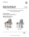
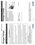
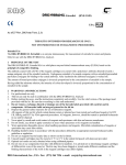
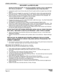
PoliPUMP Multi-outlet Grease Pump User operation and Maintenance manual Original instructions TABLE OF CONTENTS INDEX 1. 2. 1. 3. 2. 4. 3. 5. 4. 6. 5. 7. 6. 8. 7. 9. 8. 10. 9. 11. 10. 12. 11. 13. 12. 14. 13. 15. 14. 15. INTRODUCTION GENERAL DESCRIPTION INTRODUCTION PRODUCT GENERALIDENTIFICATION DESCRIPTION TECHNICAL PRODUCT CHARACTERISTICS IDENTIFICATION COMPONENTS TECHNICAL CHARACTERISTICS UNPACKING AND INSTALLING PUMP COMPONENTS OPERATING INSTRUCTIONS UNPACKING AND INSTALLING TROUBLESHOOTING OPERATING INSTRUCTIONS MAINTENANCE PROCEDURE TROUBLESHOOTING DISPOSAL MAINTENANCE PROCEDURE ORDERING DISPOSALINFORMATION DIMENSIONS ORDERING INFORMATION HANDLING AND TRANSPORTATION DIMENSIONS PRECAUTIONS HANDLING AND TRANSPORTATION OPERATING OPERATINGHAZARDS HAZARDS PRECAUTIONS Manual drawn up in accordance with EC Directive 06/42 C2204IE-NTN WK 39/14 1. INTRODUCTION This operation and maintenance manual refers to the PoliPUMP lubrication pump, and includes essential information regarding correct operating and safety procedures design to ensure safe and reliable operation of the unit. You can obtain the latest release of this document by contacting a Dropsa sales office or distributor or by visiting us on the World Wide Web at http://www.dropsa.com. It is important that this document is read and maintained in a place that anyone operating the PoliPUMP is able to consult it if necessary. 2. GENERAL DESCRIPTION 2.1. PUMP TO POINT LUBRICATION Dropsa PoliPUMP is a quick and easy product that can lubricate friction points without the use of complex metering valves or system design. It provides an affordable, versatile and easy to use product for lubrication that in a few simple steps can be setup and is ready to go. PoliPUMP has many applications including vehicle, mobile, machine tools and any type of device or machinery that requires grease lubrication from 1 to 35 lubrication points. 2.2 CHARACTERISTICS PoliPUMP contains a series of piston pumping elements driven by an eccentric CAM arrangement that provide positive displacement on the piston. It can be fitted with up to 35 pump elements (24 or 12 for smaller versions). The user can simply configures the standard pump that does not contain any pumping elements and install the designed pumping elements of their choice – simply selecting from 6 different pump element sizes accordingly. The standard version is equipped with a 2 lt reservoir and a minimum level sensing mechanism. The stirring paddle and wiper allow the grease to maintain good consistency, prevent separation, and eliminate air bubbles that may form in the grease as well as good pumping performance at low temperatures. The pump is driven by a geared motor powered at 12 or 24 VDC. The built in controller allows you to select from 12 different timing settings (see par. 7.4). 2.3 VERSIONS PoliPUMP is available in two versions: with follower plate for grease and NRUN automotive version , The follower plate required with viscous grease and when the pump needs to be able to operate in any orientation, including a fully inverted position. The NRUN version is equipped by a connection with general qualification that allows the pump to work at some time with submitted machine. So it is possible to synchronize the lubrication cycles when the vehicle is turned on. For example, connecting the NRUN signal to ignition key of the vehicle the lubrication cycles are enabled only if the machine is turned on. When switching off the vehicle/machine the pump will suspend. This means that when the pump is switched on again it will resume from its previous point. 3. PRODUCT IDENTIFICATION On the side of the pump there is a label that indicates part number of the product, operating voltage and basic characteristics. 2 4. TECHNICAL CHARACTERISTICS Pumping system GENERAL TECHNICAL CHARACTERISTICS Single acting pump elements with cam activation Drive assembly DC motor with gearbox Motor operating voltage Electronic Protection threshold for motor overload Nett weight Number of outlets / pumping max. Output connection (pumping outlet) 12V DC 24V DC 0.6 A 3 Kg (6.6 lb) 12 – 24 – 35 Push-in for Ø4 (5/32 in) 0,02cc/strokes – RED (1 notch) 0,03 cc/ strokes – GREEN (2 notches) Nominal output per pump element* 0,04 cc/ strokes – YELLOW (3 notches) 0,08 cc/ strokes – BLUE (4 notches) 0,10 cc/ strokes – GREY (5 notches) 0,13 cc/ strokes – BLACK (6 notches) Max pressure achievable at the outlet of the pumping 80 bar** Standard version 2 L (0.53 US gallons- 0,44 UK Gallons) Reservoir Capacity Version with follower plate 4 L (1.06 US gallons- 0,88 UK Gallons) Grease capability NLGI00 ÷ NLGI2 Protection grade IP 65 Operating temperature -10°C ÷ +60°C (14°F ÷ +140°F) Storage temperature -20°C ÷ +80°C (-4°F ÷ +176°F) Humidity 90% Noise < 70 db (A) Minimum level signalling/counting revolution With Hall effect sensor CONTROL PANEL CHARACTERISTICS Working voltages 12VDC – 24VDC Operating temperature -10°C ÷ +60°C (14°F ÷ +140°F) Storage temperature -20°C ÷ +80°C (-4°F ÷ +176°F) Motor Overload protection Input power protection Hardware characteristics Remote Alarm signal Completed Cycle control sensor Relay alarm contact P/N Connector (type) 0039975 (MPM 203) NC (opens in alarm) – I max 5A - Vmax 250V – Pmax 60W TECHNICAL CHARACTERISTICS CONNECTOR Nominal Voltage. N° Poles Cross section max. 250V-300V 3+ 1mm² IP 65 Max. A 10A WARNING: Do not operate the unit outside the specified voltage ranges. * NOTE: Pump output has been determined at the following conditions: Grease, NLGI 00, Standard environmental conditions (Temperature 20°C / 68°F, Pressure 1 ATM), Back pressure on outlet 5bar (72.5 psi). ** NOTE: The data refers to the maximum operating pressure of each pumping. Maximum pressure that can be delivered by the pump is a function of several variables (number of pumping elements used, type of grease, operating temperature, see par. 7). 3 5. PUMP COMPONENTS PoliPUMP (standard) Reservoir 2L (0.53 gallons) Warranty seal Paddle with wiper blade Refilling point grease nipple Pump Element Ports Control Panel Blanking Plug to substitute elements (included) Power Connector and Remote alarm Fast Refill adaptor port (M22x1.5) PUMP ELEMENTS RED - (1 notch) 0,02cc/strokes GREEN- (2 notches) 0,03cc/ strokes YELLOW - (3 notches) 0,04cc/ strokes notch Push-in outlet Ø4 BLUE - (4 notches) 0,08cc/ strokes GREY - (5 notches) 0,10cc/ strokes BLACK - (6 notches) 0,13cc/ strokes 4 PoliPUMP (with follower plate) Reservoir 4L Follower plate Stirring paddle with min level mechanism 5 6. UNPACKING AND INSTALLING 6.1 UNPACKING Once a suitable installation position has been identified, unpack the pump and prepare for installation. It is important to inspect the pump to ensure that there has been no damage during transportation. The packaging material used does not require any special disposal procedures. You should refer to you regional requirements. 6.2 PUMPING ELEMENT AND BLANKING PLUG INSTALLATION Pumping elements are not included with the pump they must be ordered and installed prior to use according to how you want to configure your pump system. Each Pump element is colour coded to represent the discharge volume and is simply screwed into the outlet port manifold. Any unused ports must be closed off with the blanking plugs (included with bare pump). To assemble the pumping elements, proceed as follows: Identify the best installation position and distribute them evenly in the ports on pumping case cylindrical manifold. N° 1 2 3 4 5 6 7 8 9 10 11 12 MOUNTING POSITION 1 1-7 1-5-9 1-4-7-10 1-2-4-7-10 1-3-5-7-9-11 1-2-4-5-7-9-11 1-2-4-5-7-8-10-11 1-2-3-5-6-7-9-10-11 1-2-3-4-5-6-7-9-10-11 1-2-3-4-5-6-7-8-9-10-11 1-2-3-4-5-6-7-8-9-10-11-12 N° 13 14 15 16 17 18 19 20 21 22 23 24 MOUNTING POSITION 13 13-19 13-17-21 13-16-19-22 13-14-16-19-22 13-15-17-19-21-23 13-14-16-17-19-21-23 13-14-16-17-19-20-22-23 13-14-15-17-18-19-21-22-23 13-14-15-16-17-18-19-21-22-23 13-14-15-16-17-18-19-20-21-22-23 13-14-15-16-17-18-19-20-21-22-23-24 N° 25 26 27 28 29 30 31 32 33 34 35 MOUNTING POSITION 25 25-31 25-29-33 25-28-31-34 25-26-28-31-34 25-27-29-31-33-35 25-26-28-29-31-33-35 25-26-28-29-31-32-34-35 25-26-27-29-30-31-33-34-35 25-26-27-28-29-30-31-33-34-35 25-26-27-28-29-30-31-32-33-34-35 Pumping elements positioning Screw the pumping elements and tighten to 10 Nm torque using a 12mm wrench. Screw the blanking plugs in the remaining holes with 10 Nm torque using a 12mm wrench or a 6 mm allen wrench. ATTENTION: Be careful when inserting the pumping element, ensuring that the thread is correctly engage to avoid any damage. 6 6.3 INSTALLING THE PUMP Using the Ø6, 5mm (0.256in) holes and 4 suitable screws place the pump and fix to its support. Assemble the pump so that the filling point and the control panel are accessible by the user. Allow 100mm (4 inches) perimeter distance around the pump for easy access. Ideally, install the pump at a height that is easily and comfortably accessible by the user to facilitate maintenance and refilling. Do not install the pump where it may be submerged by liquids of in excessively aggressive environment. Do not install the pump in hazardous areas where there may be flammable or explosive materials. Do not install near strong heat sources or electrical areas that may cause electrical interference with the control system. Ensure that tubing and wiring is appropriately secured and protected. 6.4 PUMP TO POINT GREASE LINE CONNECTIONS The Grease lines are easily connected using 4mm nylon tube. One tube per lubrication point should be used. Simply push the tube into the pumping element that is equipped with a push in fitting. Additionally there is a M22x1 port for connecting the Dropsa FAST REFILL adaptor (highly recommended). Alternatively this can be used as a remote fill line. Always ensure proper clean and filtered grease is used with the pump. WARNING: Tubing must reach the lubrication point in shortest path. 6.5 ELECTRICAL CONNECTIONS CAUTION: Before carrying out any electrical wiring you should verify the label on the pump to ensure that the correct operating voltage is being used and ensure that all power is removed. The user must provide electrical power connections ensuring correct Voltage as indicated on the label. Additional connections can be made for general remote alarm relay (or ENABLE NRUN and remote 5V alarm for automotive models - see par. 6.5.1) Connect the pump to the power supply as shown on the pump label located next to the connector. Ensure the power cable is suitable for the voltage and current used and complies with all electrical regulations. 6.5.1 Connection Diagrams Standard Connection 12VDC 24VDC Connection with general enabling (Automotive Version) 12VDC-NRUN 24VDC-NRUN 7 Connection without NRUN general enable Connection with NRUN general enable Automotive version NRUN: Connection with general enabling (NRUN) is used to operate the pump with the host machine. The pump will only operate when the enable signal is present otherwise it will remain in a standby mode indefinitely. The Automotive NRUN version is recommended for use on vehicles. Alarm The above example shows the wiring connection of the PoliPUMP with a standard vehicle. The example includes an alarm indication lamp. When the vehicle is ON the PoliPUMP is ON. When the vehicle is OFF the PoliPUMP suspends operation. Suspend means that when the vehicle is switched ON again, the PoliPUMP will resume from its previous point. 8 7. OPERATING INSTRUCTIONS 7.1 BEFORE PUTTING INTO OPERATION Note that the unit should not be dismantled by the user if a fault is found. Use gloves when handling lubricants and ensure you have checked the lubricant safety data sheet. Do not use lubricants that are incompatible with NBR (Buna) seals. Ensure that you have complied with all health and safety requirements before putting the pump into service. Maintain proper hygiene standards. Never ignore any potential danger to health. Ensure all tubing and fittings are designed to handle the maximum system pressure. Check integrity in the pump. Ensure no damage; Check and fill the reservoir. If the reservoir is below the MIN level, follow procedure 7.3 to refill; Verify the pump is at the correct operating temperature and tubing is free of air bubbles; Check the unit is properly cabled. To determine the maximum operating pressure it is necessary to know the pressure drop of the pipes connected to the pumping elements. The following diagram shows the pressure drop of the delivery pipe per length unit, according to the temperature and type of lubricant (in this case NLGI 00 grease with 160 cSt base oil and NLGI 2 with oil 180 cSt base). To ensure a fully functional system it is always necessary to verify that the pressure drop of the pipe added to the pressure required at the lubrication point does not exceed the maximum pressure that can be generated by the pump. The maximum pressures reached at the pump outlet are the following: 1÷12 pumping elements = 80 bar 1120 PSI 13÷24 pumping elements = 50 bar 700 PSI PRESSURE DROP 25÷35 pumping elements = 35 bar 490 PSI Pipe: ø4 x ø2 7.2 OPERATION Check and set the timer selection. Ensure remote enable is activated on Automotive NRUN version Check that the pump is running. Check lubricant is being delivered to the greasing points as necessary. 9 7.3 REFILLING THE RESERVOIR Ensure that all ports have been occupied either by pump elements or blanking plugs. The refilling of the tank is carried out through the dedicated filling ports with adequate filtration to ensure clean lubricant. Continue to fill unit until the max level is reached this level should not be exceed. In the event the user overfills the tank, the excess lubricant will be expelled through vent holes located under the lid. REFILL CARTRIDGE ADAPTOR (Part No. 888038) Manual Grease Nipple Filling Point WARNING: to avoid introducing contamination into the pump and voiding the warranty ensure that refilling is always carried out through the designated ports using clean grease. Refer to 14.2 for more information about lubricant characteristics. 7.4 CONFIGURATION Control display layout GREEN LEDs Displays the current lubrication cycle setting UP ARROW Increases the frequency of lubrication cycle DOWN ARROW Decreases the frequency of lubrication cycle RESET/EXTRA CYCLE Reset alarms start a lubrication cycle Currently not used future expansion Hold for 3s to lock controller YELLOW LED - LOCK Indicates the Keypad is locked. This avoids accidental changing of the lubrication setting YELLOW LED PUMP MOTOR RUNNING The pump motor is running RED LED: LOW VOLTAGE/BATTERY or OVERVOLTAGE The input power voltage is outside the safe operating range RED LED MINIMUM LEVEL Indicates Low level in tank RED LED MOTOR BLOCK The pump exceeded the maximum level of current absorption or has detected time out cycle 10 7.4.1 Setting the Lubrication Cycle The integrated control board manages the timing, start and stop of the lubrication cycle according to the setting selected by the user using the UP and DOWN ARROWS. The default setting is 2 cycles/min. The lubrication frequencies available are: • Cycles per minute: 0.5 – 1 – 2 • Cycles per hour: 3 – 4 – 6 – 10 – 20 • Cycles per day: 12 – 24 – 32 – 48 Alternatively, expressed in minute between cycles: • Lubrication interval: 0,5 – 1 – 2 – 3 – 6 – 10 – 15 – 20 – 30 – 45 – 60 – 120 minutes Once cycle means one injection of grease from each of the pumping elements installed. The pump will complete one full rotation. 7.4.2 Cycle Monitoring and Minimum Level Signalling A Magnetic sensor installed inside the control system monitors the rotation of the cam that activates the pump modules. This allows the PoliPUMP to know exactly one rotation and therefore one cycle. Additionally the paddle that rotates will position itself differently in the absence of grease, thereby providing a low level alarm. The Low level alarm is not cleared by powering the unit off and back on. The only way to clear the low level signal is to press the RESET button on the pump. This will run a lubrication cycle and position the paddle in order to correctly monitor if the grease has been replenished in the reservoir. 7.4.3 Cycle Start synchronization When the system first starts the pump performs the first lubrication cycle. The position of the pump cam is not known and may not necessarily be in its predetermined start/stop position. The control system, on first cycle will move the pump cam to the start /stop position. This is known as cycle synchronization. After the first cycle the pump will always start and finish a lubrication cycle from its predetermined start position. In the event of a power failure the cycle will resume from where the power failed and complete the lubrication cycle by bringing the pump cam to the predetermined start/stop position. 7.4.4 Performing a manual or additional lubrication cycle. Should it be required, press the Reset button when the pump is not operating to run an additional lubrication cycle. 7.4.5 Alarm and Over-load protection The built in control system manages the following alarms: - - - Minimum level As described in par. 7.4.2, the Alarm LED is lit. Time out cycle If no sensor signal is received within one minute an alarm condition occurs and the pump is stopped. Motor block The motor is absorbing too much current and it likely blocked. The Motor block LED is lit. Pump will not continue until Reset is pressed. Low voltage/battery low If the input voltage is too low (for example discharged battery power) the battery LED is lit. Once power is restored to the minimum supply voltage the pump will continue. A reset is not necessary. Over-voltage condition If the input voltage exceeds the maximum safe working voltage of the pump the pump will not activate. The battery LED will blink until the voltage returns within valid operating range. The pump will restart by itself. A reset is not necessary. 7.4.6 Keyboard Lock/unlock After setting the desired lubrication cycle, you can lock the keyboard by pressing the Up Arrow and Down Arrow buttons for 3 seconds, to unlock repeat the same operation. This prevents unintentional modification of the lubrication cycle. 11 7.4.7 Disabling and Enabling the Minimum level sensor (from fw 1.15 version) If you need to disable the minimum level alarm from Press Reset and down arrow. The alarm LED (motor block LED) will blinks for about 3 seconds confirming the setting, after which you can release the buttons. In this mode, the pump signals the minimum level via corresponding blinking LED and switching the remote alarm signal but continues to operate normally according to the cycle time setting. + Minimum level disable To re-enable the minimum level alarm press and hold the Reset button and up arrow. The alarm LED for about 3 seconds, after which you can release the buttons. + (motor block LED) blinks Minimum level enable * NOTE: In case there is an alarm for over / under voltage during the 3 seconds required to enable/disable the minimum level, the fault LED will not blink but remain lit. 12 8. TROUBLESHOOTING Below is a trouble shooting table to show possible problems and solutions. If you are in any doubt about the correct solution to fixing a problem, do not dismantle parts of the PoliPUMP but contact an Authorized Dropsa Sales and Service Point for technical assistance. PROBLEM Pump Motor does not operate Pump is operating but no lubricant reaches points Lubricant does not reach lubrication points on each pump cycle or irregularly TROUBLESHOOTING TABLE POSSIBLE CAUSE REMEDIAL ACTION Check the power lines, ensure that any fuse installed is still Power missing. intact. Electronic Controller does not Replace electronic card function Geared motor no longer works Replace gear motor assembly Check the condition of tubing in the system and ensure that Tubing is disconnected it is correctly secured and not blocked for example, by hardened grease. Incorrect setting of the cycle time. Select a more frequent lubrication cycle. Reservoir is empty No lubricant from pump The pump starts the lubrication cycle but then immediately stops Refill, and verify if any low level alarm is activated Disconnect the primary tubing from the pump and operate a lubrication cycle. Air bubble in grease Check that clean, air free grease is coming from the pump and then reconnect the tubing. Some lubricants are not suitable for automatic pumping Incompatible lubricant systems. Replace the grease. Dismantle the pumping element and check for Blocked pumping element contamination. Clean and reinstall or repalce Worn pump element Replace pump element Pump element Check worn Replace pump element Allow the pump to cool. Retry the lubrication cycle. If the Defective or blocked Pump motor. problem persists It will be necessary to replace the pump motor assembly : Allowed only for specialised Dropsa’s staff when retuned for repair (send the product to Dropsa). ALARM CODES LED ALARM Gear motor overload Cycle does not perform in predetermined maximum time. Low lubricant level in reservoir REMEDY Leave the motor to cool for a few minutes and try again. Check to see that the pump is operating normally and there is no contamination in the tank that may be blocking the motor. Check the motor is free to operate and there is no contamination in the reservoir. Replace the sensor or damaged gear motor if necessary. Customers are advised to contact a registered Dropsa dealer. Refill with clean lubricant. If using a battery, check the charge on the battery and replace if necessary. Input Voltage outside permitted range Check that the supply voltage is not outside permitted thresholds. NOTE: To cancel alarm messages push "Reset". 13 9. MAINTENANCE PROCEDURE WARNING: Before carrying out any maintenance operation, ensure that power and hydraulic system are disconnected. The pump does not necessitate any special tool for operation and maintenance. When working with the pump it is nonetheless recommended that personal health and safety equipment is used as is normal for any operation in an industrial or similar workplace. The pump has been designed and built as to require minimal maintenance and operate in different and challenging operating environment. It is recommend that the unit is inspected and kept clean to ensure long life and trouble free operation. It is important to check all tubing on the system to ensure that it is always tight and leak free. 9.1 Programmed and operational Maintenance The following operations should be performed on the pump. ITEM Integrity of tubing and system Reservoir level Filling Filter FREQUENCY After initial 500 hours. Every1500 hours. As needed. As needed, or once per year. OPERATION Check fittings and tubing secured. Verify components are correctly fixed to machine. Top up level with clean lubricant. Check and replace as necessary. 10. DISPOSAL During maintenance or disposal of the machine care should be taken to properly dispose of environmentally sensitive items such as oils or other lubricants. Refer to local regulations in force in your area. When disposing of this unit, it is important to ensure that the identification label and all the other relative documents are also destroyed. 11. ORDERING INFORMATION N° Max. PUMPING 12VDC Industrial 0888270 0888271 0888272 12 24 35 N° Max. PUMPING 12VDC Industrial 0888282 0888283 0888284 12 24 35 0,02cc/ cycle 0888451 PART NUMBER 5717300 5717218 5717258 5717259 PART NUMBER 0888257 0888116 0,03cc/ cycle 0888452 STANDARD PUMP POWER 24VDC 12VDC Industrial Automotive (NRUN) 0888273 0888276 0888274 0888277 0888275 0888278 PUMP WITH FOLLOWER PLATE POWER 24VDC 12VDC Industrial Automotive (NRUN) 0888285 0888288 0888286 0888289 0888287 0888290 PUMPING FLOW RATES 0,04cc/ cycle 0,08cc/ cycle 0888453 0888454 OPTIONAL PART DESCRIPTION NUMBER Ø4x3 Nylon Tube (low pressure) Clear 100 m coil 0888038 Ø4x2 Nylon Tube - Clear 100 m coil 3133723 Ø4x2 Nylon Tube - Black 25 m coil 0888386 Ø4x2 Nylon Tube - Black grease filled NLGI 00 25 m coil SPARE PARTS PART DESCRIPTION NUMBER Blanking Plugs for unused pump elements 3130022 Reservoir (standard) 24VDC Automotive (NRUN) 0888279 0888280 0888281 24VDC Automotive (NRUN) 0888291 0888292 0888293 0,10cc/ cycle 0888455 0,13cc/ cycle 0888456 DESCRIPTION Grease cartridge filling kit Grease cartridge filling kit with valves Clamping kit (only for version with follower plate) DESCRIPTION Replacement filling filter 14 12. DIMENSIONS PoliPUMP (standard) Dimensions in mm [in]. 15 PoliPUMP (with follower plate) Dimensions in mm [in]. 16 13. HANDLING AND TRANSPORTATION Prior to shipping, the equipment is carefully packed in cardboard package. During transportation and storage, always maintain the pump the right way up as indicated on the box. On receipt check that package has not been damaged. Then, store the machine in a dry location. 14. PRECAUTIONS WARNING: It is necessary to carefully read about the instructions and the risks involved in the use of lubrication machines. The operator must know the machine functioning through the User and Maintenance Manual. Power supply Any type of intervention must not be carried out before unplugging the machine from power supply. Make sure that no one can start it up again during the intervention. All the installed electric and electronic equipment, reservoirs and basic components must be grounded. Flammability The lubricant generally used in lubrication systems is not flammable. However, it is advised to avoid contact with extremely hot substances or naked flames. Pressure Prior to any intervention, check the absence of residual pressure in any branch of the lubricant circuit as it may cause oil sprays when disassembling components or fittings. Noise Pump produces noise, not more than 70 dB(A). 14.1 LUBRICANTS NOTE: The pump has been designed to operate with grease max NLGI 2. Always use lubricants compatible with NBR (Buna) Rubber seals. Any residual lubricant found on new units is residual NLGI 2 test grease used during the assembly of the pump. The following is a comparison table between NLGI (National Lubricating Grease Institute) and ASTM (American Society for Testing and Materials) between greases, showing the permissible values for the PoliPUMP. For further technical information and on safety information consult the lubricant MSDS Safety data sheet or equivalent document supplied by the lubricant manufactuer. GREASE NLGI ASTM 00 400 – 430 0 355 – 385 1 310 – 340 2 265 – 295 15. OPERATING HAZARDS The verification of conformity with the essential safety requirements and regulations of the Machine Directive is effected by means of the compilation of a check list which has been pre-prepared and is contained in the technical file. The lists which are utilised are of three types: list of dangers (appendix A, EN 1050). application of essential safety requirements. electrical safety requirements (EN 60204). Following is a list of dangers which have not been fully eliminated but which are considered acceptable: During installation there may be small low pressure oil seepage from the pump. Always use appropriate protective clothing, gloves and take all necessary safety precautions. Contact with lubricant during maintenance or filling of the reservoir. As per previous point, correct precautions must be taken to protect from contact with lubricant. Moving Parts and crush danger. All moving parts are enclosed within the pump unit. Do not open the pump unit. Appropriate danger labels are located on the pump. Electric shock. All electrical connections must be carried out by a qualified electrician who has studied the connection to ensure no electrical danger. Abnormal operation posture. The pump should be installed in a suitable position with ample clearance as indicated in this manual to avoid abnormal posture for the operator. Unsuitable Lubricant. Lubricant characterstics are indicated on the pumpa nd in this user manual. In any case contact a Dropsa Sales and Support engineer (if in any doubts, contact the Technical Department Dropsa SpA). FLUIDS EXPLICITY NOT ALLOWED Fluid Dangers Lubricants with abrasive additives Wear of the components inside the pump Lubricants with silicone based additives Pump seizure Petrol – solvents – inflammable liquids Fire – explosion – damage to the gaskets Corrosive products Pump corrosion - damage to people Water Pump oxidation Food substances They would be contaminated 17