Transcript
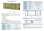
INSTALLATION INSTRUCTIONS
ZW3K
Wireless Home Automation Control Device
3 - Way Control Auxiliary Switch
IMPORTANT NOTE ABOUT 3-WAY CIRCUITS
The term “3-way circuit” refers to a circuit with two switches and one load (light)
like you find at the top and bottom of a stairway. There are many ways to physically
wire a 3-way circuit and it is important to understand how the circuit you wish to
upgrade to Z-Wave control is wired. Below is a description of a typical 3-way circuit.
One of the ways to wire a two-switch/one-load circuit is to route the incoming power
through the first switch, then to the second switch and then to the load. Although very
common and by no means a standard, it is the easiest to convert to Z-Wave control.
FEATURES
Ideal Z-Wave device to work with on/off switch (ZW15S) and dimmer switch
(ZW500D) for controlling one load from two locations.
Manual On/Off & Dim control of any connected load through traveler wire.
Air-Gap Switch feature meets UL requirement and disconnect power from load locally.
Includes two free wall plates, screwless and standard wall plate.
With this type of circuit, Switch 1 is replaced by the Z-Wave auxiliary switch and
Switch 2 is replaced with the primary Z-Wave switch. The auxiliary switch does
not actually control the power; instead, it sends a momentary voltage signal
through the traveler wire to the primary switch which in turn, controls the power
to the load.
Optional for 3-Way Control:
Typical 3-way circuit:
Black
Red
Black
DESCRIPTION
Yellow
The ZW3K 3-Way Control Auxiliary Switch is designed to work with on/off switch
(ZW15S) and dimmer switch (ZW500D) in order to control one light/load from two
locations, such as staircase, hallway, and multi-entrance room. This Z-Wave
auxiliary switch is not Z-Wave enabled and must be used with one of the above
Z-Wave devices. Sliding Air-gap switch to totally disconnect power while replacing
light bulbs and preventing from leakage current from the fixture(s). Use this ZW3K
3-Way Auxiliary Switch is to reduce energy consumption and provide more
convenient to you and your family.
WARNINGS AND CAUTIONS
To be installed and/or used in accordance with appropriate electrical codes
and regulations. Exercise extreme caution when using Z-Wave devices to
control appliances. Operation of the Z-Wave device may be in a different
room than the controlled appliance, also an unintentional activation may
occur if the wrong button on the remote is pressed. Z-Wave devices may
automatically be powered on due to timed event programming.Depending
upon the appliance, these unattended or unintentional operation could
possibly result in a hazardous condition.
Z-Wave enabled devices should never be used to supply power to, or
control the On/Off status of medical and/or life support equipment.
If you are unsure or uncomfortable about performing the installation,
please consult a qualified electrician.
Switch 1
Switch 2
Please consult an electrician if you have trouble identifying the type of wiring
circuit you wish to convert or if you do not feel confident in your ability to
convert the circuit to Z-Wave control.
3-Way Wiring Schematic using one ZW15S/ZW500D and one ZW3K
White (Neutral)
Red
(Load)
Traveler(Yellow)
Z-Wave
ZW15S/
ZW500D
Z-Wave
ZW3K
OPERATIONS
Work with dimmer switch (ZW500D):
Press and release the top of the ZW500D’s button to turn the connected lighting
ON and return the brightness level to its previous setting.
Press and hold the top of the ZW500D’s button to turn the connected lighting
ON and set the brightness level. Release when the desired level is reached.
Press the bottom of the ZW500D’s button to turn the connected lighting OFF.
Press and hold the bottom of the ZW500D’s button to dim the brightness level
down. Release when the desired level is reached.
Work with on/off switch(ZW15S):
Press and release the top of the ZW15S’s button to turn the connected lighting ON.
Press the bottom of the ZW15S’s button to turn the connected lighting OFF.
Green (Ground)
Black (Hot)
This switch may be used in new installations or to replace an existing wall switch
when converting a 3 way circuit to Z-Wave. It can not be used by itself for single
pole control.
-01-
-02-
INSTALLATION
1. The ZW3K requires the following 3 wiring connections:
a. The Traveler wire. This is used to send voltage signals to the primary Z-Wave
switch. The signals tell the Z-Wave switch what action to perform.
b. Ground.
c. Neutral.
White
1. WARNING : To avoid fire,shock ,or death.Turn off power at circuit breaker
or fuse and test that power is off before wiring.
2. Remove wall plate, switch mounting screws.
3. Carefully remove the switch from the switch box. DO NOT disconnect the wires.
4. There are five wiring connections on the Z-Wave dimmer and switch; these are
marked HOT, NEUTRAL, LOAD, GROUND and TRAVELER. The Traveler
terminal is only used for 3-way wiring and should be insulated if the dimmer/
switch is being installed in a single pole (one switch & one load). Match these
screw terminals to the wires connected to the existing switch.
5. Disconnect the wires from the existing switch
6. Connect the green wire to the GROUND terminal.
7. Connect the white wire to the terminal marked NEUTRAL.
8. Connect the red wire that goes to the light to the terminal marked LOAD.
9. Connect the black wire to the terminal marked HOT.
10.Connect the Traveler(yellow) wire(not included) to the screw terminal marked
TRAVELER. The other end of this Traveler wire connects to the TRAVELER
terminal on the ZW3K Auxiliary Switch. The TRAVELER terminal must be
insulated if you are not using it. See the following section for information
about wiring the ZW3K Auxiliary Switch.
11. Check connections to be sure they are tight and no bare conductors are
exposed.
12. Insert the switch into the outlet box carefully.
13. Make sure the switch to the box using the supplied screws.
14. Attach the wall plate.
15. Restore power to the circuit breaker and test the system.
WARRANTY INFORMATION
Our company warranties its products to be free of defects in materials and workman-ship for a period of two (2) years. There are no obligations or liabilities on the part
of our company for consequential damages arising out of or in connection with the
use or performance of this product or other indirect damages with respect to loss
of property, revenue, or profit, or cost of removal, installation or reinstallation.
Mar, 2014
11006A
-03-