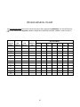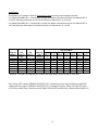
1
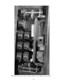
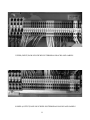
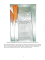
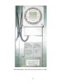
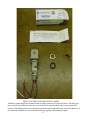
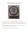
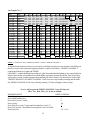
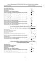
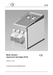
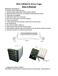
LIGHTING
CONTROL PANEL
Installation Guide & User Manual
925 A .E.C . D R IVE , W O O D D A LE, IL 60191
(630) 238-1516 / FA X (630) 860-2934
THIS PAGE INTENTIONALLY LEFT BLANK
2
WARRANTY STATEMENT
Automated Controls & Systems (ACS) warranties its equipment against defects in workmanship and materials for a period of 90 days (labor) and 12 months (parts) from date of
installation.
Warranty applies only to original installation and to equipment subject to normal use and
service when such equipment is used in accordance with instructions furnished by ACS.
Warranty does not cover against damage by abuse, faulty installation, improper electric
current or alterations made after shipment.
ACS’s liability under this warranty shall be limited to the replacement or repair of any
equipment or part which has been returned, prepaid to the factory, and which has been
determined, upon examination by ACS to be defective.
Under no circumstances shall ACS be liable to Buyer or any third party for any loss of
profits or other direct or indirect costs, expenses, losses or consequential damages arising
out of or as a result of parts or components incorporated in ACS’s equipment but not supplied by ACS.
Operation of this unit on any voltage other than the specified operating voltage will void
warranty.
THIS WARRANTY IS IN LIEU OF ANY OTHER WARRANTY, EITHER EXPRESSED OR IMPLIED, AS TO DESCRIPTION, QUALITY, MERCHANTABILITY, FITNESS FOR ANY PARTICULAR PURPOSE OR USE, OR ANY OTHER
MATTER.
3
LIGHTING CONTROL PANEL User Manual
TABLE OF CONTENTS
WARRANTY
3
SPECIFICATIONS
5
PRINCIPLE OF OPERATION
6
GENERAL DESCRIPTION
6
INSTALLATION & DETAILS
7
PROGRAMMABLE TIME SWITCH
16
LIGHTING SCHEDULE
17
SET TIME AND DAY
18
PROGRAMMING
18
REVIEW AND CHANGE OF PROGRAMS
19
MANUAL OVERRIDE
19
MANUAL DAYLIGHT SAVINGS TIME CHANGEOVER
19
PROGRAMMING CHART
20
PROGRAMMING EXAMPLE
21
BLANK PROGRAMMING CHARTS
28
TROUBLESHOOTING
PARTS ORDERING/RETURN INFORMATION
PARTS IDENTIFICATION
APPENDICES
LC PANEL
LC-HD PANEL
EXTENTION PANELS
GLOSSARY
4
SPECIFICATIONS
ELECTRICAL
Controls:
3A 1PH 120V 50/60HZ
Power:
Model LC
24A 120 - 240V - 28 Circuits
Model LC-HD
48A 120 - 240V - 4 Circuits
24A 120 - 240V - 24 Circuits
Model LC-EC
24A 120 - 240V - 32 Circuits
Model LC-HD-EC
48A 120 - 240V - 4 Circuits
24A 120 - 240V - 28 Circuits
ENVIRONMENTAL
Operating Temperature:
Humidity:
0 - 60 Degrees Centigrade
(32 - 140 Degrees Fahrenheit)
10 - 90% Relative Humidity
5
PRINCIPLE OF OPERATION
The Lighting Control Panel is used to control the outside lights of the restaurant. It does this by turning the
parking lot lights ON or OFF as a group via a program on one channel of the “GRASSLIN 7 Day Time
Switch.” The other channel is used to control the outside signage lights as a group. The program is modified by
the condition of the ambient light via the Photo Control. If the program calls for the lights to be on and it is still
light outside, the Photo Control inhibits the operation of the lights until it is dark. Conversely, when the lights
are on and daybreak occurs, the lights will turn off. The BY-PASS SWITCH must be in the PHOTO CONTROL position for this to happen. If it is in the MANUAL position, the lights are fully controlled by the hand
symbol 1 and hand symbol 2 keys.
GENERAL DESCRIPTION
ACS’s Lighting Control (LC) Panel is an industrial control panel with contactors and other control elements
including a user friendly microcomputer based two channel electronic time switch (timer). This allows for the
automatic control of the exterior lights of the restaurant.
• Channel 1 includes Road Sign(s), Facia Signs, Roof Signs, Roof Beams and Soffit Lights.
• Channel 2 is assigned to the Parking Lot Lights.
Timed parking lot light control gives employees leaving the building at night the security of being able to walk
to their cars in a lighted environment.
The LC Panel uses a roof mounted Photo Control which prevents the exterior lighting system from turning ON
while daylight is present. The Photo Control has a sliding cover which controls the amount of light sensed by
the photocell. The electronic time switch in conjunction with the roof mounted Photo Control control the ON/
OFF cycling of the building’s exterior lights. To successfully turn any lighting control channel ON, the Photo
Control must sense a “dark” condition and the particular timed channel must be in an ON state.
The LC Panel also provides a Photo Control bypass switch. This switch, labelled MANUAL/PHOTO CONTROL, allows one to bypass the Photo Control control feature of the lighting control system. When the switch
is in the MAN (manual) position, the Photo Control no longer has any effect on the exterior lights.
6
INSTALLATION
This unit may only be installed by a licensed electrical contractor. It should be installed as specified in the
electrical drawings provided to the construction contractor. All wiring must meet both NEC and local
electrical codes.
The LC Lighting Control Panel consists of three parts: a rough-in box (enclosure); an outer door, inner door
and mounting collar assembly; and a subplate containing the actual controls and contactors.
The unit is designed to be mounted between standard wall studs (16” on center). Placement is to be as
specified in the contractor’s drawings. All input power wiring comes from the “LP” circuit breaker panel
and enters the lighting control panel from either side of the rough-in box (enclosure) or the top/bottom.
Knock-outs are provided at these locations.
MODEL LC LIGHTING CONTROL PANEL WITH MAIN DOOR OPEN
7
Switched power runs from the Lighting Control Panel to the Road Sign(s), Facia Signs, Roof Signs, Roof
Beams and Soffit Lights(timing channel No. 1) and the Parking Lot Lights (timing channel No. 2). Each
contactor is wired with a different color wire and the colors of the wire correspond to the colors of the terminal
blocks. The circuit attached to the terminal block on the top portion of the unit follows through to the corresponding terminal block at the bottom portion of the panel.
Each channel is independently programmed via the GRASSLIN Time Switch. Programming instructions
start on page 15.
M odel: LC (LC -H D )
A U T O M AT E D C O N T R O L S & S Y S T E M S , In c.
1
3
5
7
2
4
6
8
2
4
6
6
1
3
5
7
1
3
5
7
2
4
6
8
2
4
6
6
L C -EC A N D
LC
L C -H D -EC
LC
PA N E L S O N LY
C O N TA C T O R S
1
3
5
7
1
3
5
7
2
4
6
8
2
4
6
8
1
3
5
7
1
3
5
7
4
6
2
4
6
8
2
8
C -2
C -3
C -4
C -5
-5
C -6
POWER FOR
LC PANEL
20A 1Ø 120V
BLK
WHI
WHI
BLK
• R o a d Sign
C-1
(L 1, L 2 ; T 1, T2 )
(L1,
Paa rrkkin
in g Lo t L igh ts
•P
C-5
( L17
(L
17 , L 18 , L 19 , LL2
2 0;
T 17
T1
7, T
T118
8,, T
T11 99,, T
T220)
0)
• R o o f Bea m s
C-2
(L 5, L 6 , L 7 , L 8;
(L5,
T 5, T 6, T 7 , T 8 )
C-6
((LL21
21 , L 22 , L 23 , LL2
2 4;
T 21
T2
1, T
T222
2,, T
T22 33,, T
T224)
4)
ig hts
• S offit LLig
C-3
(L 9, L 1 0; T9 , T1 0 )
(L9,
C-7
((LL25
25 , L 26 , L 27 , LL2
2 8;
T 25
T2
5, T
T226
6,, T
T22 77,, T
T228)
8)
• Fa s cia S ig n
C-4
(L13
(L 13 ; T1 3 )
C -7
CONTROL
TO LC-2RS
PANEL
T E R M IN A LS F O R “L P ” C IR C U IT B R E A K E R PA N E L
WHI
TIM
T
IM IN G
C H A NN
N N EL
NO. 2
RED
C -1
T E R M IN A L
BLOCKS
T IM IN G
C H A N N EL
NO. 1
GROUND
7
BLK
5
BRN
3
C -7
WHI
1
C -6
CONTROL
AND POWER
TO LC-EXT
PANEL
C -5
-5
RED
C -4
BLU
Spare
PARKING
LOT
LIGHTS
Spare
Spare
Spare
Fascia Sign
C -3
WHI
C -2
Spare
SOFFIT
LIGHTS
ROOF
BEAMS
Second
Road
Sign
spare
ROAD
SIGN
C -1
BLK
T ER M IN A L S
F O R P H O TO
C O N TR O L
TE R M IN A L S FO R E X TE R IO R L IG H T
TIN
IN G C IR C U IT S
GROUND
Te rm in a l B lo c k s A rra n g e m e n t
orre
rre c t P h oto
o to C o n tro
troll w irin g a nd a d ju stm e n t a
are
re critic a
all fo r re lia b le P a n e l o
op
pe
e ra tion .
A ttention
ttentio n:: C o
F o r dde
e ta ils s e e L C P a ne l w irin g d
diag
iag ra m a n d P h o to C o n trol
tro l aap
p p lic a tio n s h
he
e e t.
For tech
nical suppo
sup port
technical
rt call A C S at (630) 238-1516
INSIDE INNER DOOR LABEL DETAILING LOCATION OF CIRCUITS
8
OVERALL VIEW OF LC PANEL SHOWING SUB PLATE WITH CONTACTORS
9
DETAILED VIEW OF CONTACTORS, WIRING AND TERMINAL BLOCKS
10
UPPER (INPUT) ROW OF SCREWLESS TERMINAL BLOCKS AND LABELS
LOWER (OUTPUT) ROW OF SCREWLESS TERMINAL BLOCKS AND LABELS
11
SCREWLESS TERMINAL BLOCK TOOL AND INSTRUCTIONAL LABEL FOR USE
The screwless terminal blocks are a tension clamp device. Put the special tool in the square hole as shown in
the above label to open the clamp. Then insert the stripped wire into the oval hole. Now pull out the tool and
the wire is securely captured by the terminal block. The large terminal blocks require a standard round
shank screwdriver with a diameter of about 1/4”. Otherwise operation is the same.
12
MANUAL/PHOTO CONTROL SWITCH AND CONTROL CIRCUIT
BREAKER
13
PROGRAMMABLE TIME SWITCH AND CHANNEL ID LABEL
14
PHOTO CONTROL SUPPLIED WITH LC PANEL
ThePhoto Control supplied is mounted on the roof and wired to the LC Panel as follows. The black wire
goes to the PE-H terminal, the white wire goes to the PE-N terminal and the red wire goes to the PE-L
terminal. The sliding metal cover is adjusted to set the amount of light which will activate the photoeye. It
also should be mounted so it will not be affected by the signage or the parking lot lights.
15
PROGRAMMABLE TIME SWITCH
ACS’s Lighting Control (LC) Panel uses a two-channel programmable time switch shown above.
Up to 42 ON or OFF events, in any combination, can be programmed into the timer. If the same ON or OFF
time is used on more than one day it is counted as one (1) event even though it could be used all seven days of
the week.
The timer has an internal battery which saves any events programmed into its memory in the case of a power
failure. The battery back up should be valid for about two weeks.
The information required for setting and programming this time switch follows.
16
The following information shows how to program the GRASSLIN, Two Circuit Electronic, 7 Day Time
Switch, model Digi 42/2, installed in McDonald’s LIGHTING CONTROL PANELS model LC and LCHD. It is followed by a detailed example.
I.
Lighting Schedule
ACS’s Lighting Control Panel provides two timing channels to control exterior lights of the store.
See picture on page 7 for label indentifying location of circuits and capacity (amperage).
TIMING CHANNEL NO. 1
• Road Sign
• Facia Sign
• Roof Beams
• Soffit Lights (100%)
TIMING CHANNEL NO. 2
• Parking Lot Lights (100%)
Usually, CH1 of the Time Switch for this channel should stay ON during store business hours (e.g. from 6
AM to 11 PM) and CH2 of the Time Switch for this channel should stay ON from about an hour before the
store is open to about an hour after the store is closed (e.g. from 5 AM to 12 AM).
NOTES:
A.
B.
C.
If an input is missing or incomplete, the missing segments will flash when the clock symbol
or Prog. key is depressed. For example, if no ON or OFF is selected, the ON symbol will
flash. The missing entry must be completed before programming can resume.
While programming, pressing the h or m key longer than 2 seconds will cause a rapid roll
of parameter.
A program consists of:
1.
ON or OFF command
2.
Hour and minute
3.
Day or multiple days on which it is to occur.
17
Setting Time and Day of Clock
IMPORTANT: Depress reset key (Res.) before beginning to set time and programming.
A.
Select military (24:00 hr.) or AM/PM (12:00 hr.) time by depressing and holding h key
while pressing +/-1h key to toggle between military and AM/PM. (AM appears in display
when in AM/PM mode.)
B.
Press and hold down clock symbol key.
C.
Press +/-1h key once if setting the timer when daylight time is in effect (+1h appears in
display).
D.
Set hour with h key.
E.
Set minutes with m key.
F
Press Day key repeatedly to the day of the week. (1 is Monday, 7 is Sunday)
G.
Release clock symbol key, colon will begin flashing.
II.
Programming
A.
Press Prog. key, “1 2 3 4 5 6 7” and “—:—” will appear in display. (Pressing Prog. key
again, display will show the number of free programs: “Fr 42”) Press again to advance to 1st
program.
B.
Press hand symbol 1 (for Timing Channel No. 1) or hand symbol 2 (for Timing Channel
No. 2). ON symbol will appear below CH1 or CH2. Pressing the key again will toggle to
OFF. Pressing a third time clears the ON/OFF for the channel from the program. Pressing
again returns to ON. Select ON or OFF for the program with the hand symbol key.
C.
Press h to select hour for switching time.
D.
Press m to select minute for switching time.
E.
Press Day key, a flashing underline appears below day 1. Pressing the Day key a second
time advances the underline to day 2, etc. Use the Day key to advance to a day of the week
to be omitted from the program and press the Sel. (select) key, the day will flash. Continue
pressing Day and Sel. keys to omit days until only the desired days remain and are not
flashing.
F.
Press Prog. key and repeat steps “B” through “E” to enter additional programs of ON and
OFF times.
G.
Press clock symbol key to enter run mode.
NOTES:
1. A flashing display indicates either incomplete data entry or the battery is low. Check to see if days and
ON or OFF times are entered, and check the power supply to the time control.
2. The output relays will switch ON (or OFF) only at programmed times. After programming is completed,
if a channel should be ON, it must be manually turned ON with the hand symbol key. For example,
programming is completed at 2PM and CH1 was programmed to be ON at 6AM and OFF at 11PM. After
pressing the clock key, CH1 will be OFF; press hand symbol 1 to turn it ON.
18
III.
Review and Change of Programs
A.
To review a program at any time, press Prog. key. Programs will be displayed in the sequence
they were entered with repeated presses of Prog. key.
B.
To change a program, select the program to be changed with Prog. key, and enter the new
time of day, and/or days of week just as in the programming steps shown above. The old
program is overwritten with the new selections. Press Prog. to store the new program.
To delete an individual program, select the program as in step “A” and press the m key and
C.
then the h key until “—:—” appears in display. Press either Prog. or clock symbol key
until “—:—” flashes. The program is deleted after few seconds.
IV.
Manual Override
While in the Run mode, (clock symbol is displayed)
1.
Pressing the hand symbol key will reverse the load status (switch load OFF if it is ON,
or switch ON if it is OFF). A hand symbol appears in display to indicate the override is
active. At the next scheduled switching time, automatic time control will resume, eliminating override.
2.
Pressing the hand symbol key a second time, load ON symbol in square brackets
appears in the display indicating the load is switched permanently ON.
3.
Pressing the hand symbol key a third time, load OFF symbol in square brackets
appears in the display indicating the load is switched permanently OFF.
4.
Pressing the hand symbol key a fourth time returns to automatic, clock symbol appears in the display.
V.
Manual Daylight Time Changeover
The Digi 42/2 offers manual daylight time changeover in the spring and fall. Depressing the +/-1h
key sets clock time up or down 1 hour to change the time twice a year as required for day light savings
time and standard time.
19
PROGRAMMING CHART
The Programming Chart shown below may be used as an aid to program the GRASSLIN, Two Circuit Electronic,
7 Day Time Switch model Digi 42/2 installed in McDonald’s LIGHTING CONTROL PANELS model LC and LCHD.
Day of the Week
Program
Number
CH1
(ON/OFF)
CH2
(ON/OFF)
Switching
Time
MO (1)
2
3
4
5
6
7
8
9
10
11
12
20
TU (2)
WE (3)
TH (4)
FR (5)
SA (6)
SU (7)
An Example:
The following is an example of filled out Programming Chart according to typical lighting schedule.
For TIMING CHANNEL NO. 1, from Monday to Friday Time Switch CH1 should be ON at 6:00 AM and OFF at
11:00 PM, Saturday and Sunday CH1 should be ON at 6:00 AM and OFF at 12:00 AM*.
For TIMING CHANNEL NO. 2, from Monday to Friday Time Switch CH2 should be ON at 5:00 AM and OFF at
12:00 AM, Saturday and Sunday CH2 should be ON at 5:00 AM and OFF at 1:00 AM.
Day of the Week
Program
Number
1
2
3
4
5
6
7
8
CH1
(ON/OFF)
ON
OFF
ON
OFF
CH2
(ON/OFF)
ON
OFF
ON
OFF
Switching
Time
6:00 AM
11:00 PM
6:00 AM
12:00 AM
5:00 AM
12:00 AM
5:00 AM
1:00 AM
MO (1)
1
1
1
1
TU (2)
2
2
2
2
WE (3)
3
3
3
3
TH (4)
4
4
4
4
FR (5)
5
5
5
5
SA (6)
SU (7)
6
7
7
6
6
1
7
7
* Attention: 12:00 AM is the beginning of a new day (the lights will go off the next day at 12:00 AM).
Time Switch CH1 controls TIMING CHANNEL NO. 1 (Road Sign, Facia Sign, Roof Beams and Soffit
Lights) and CH2 controls TIMING CHANNEL NO. 2 (Parking Lot Lights). When CH1 and CH2 when
are ON they enable Photo Control to turn the lights ON and OFF automatically with the ambient light level.
21
An Example No. 2
12 H O U R
T IM E
12:0 0 A M
1:00 A M
2:00 A M
3:00 A M
4:00 A M
5:00 A M
6:00 A M
7:00 A M
8:00 A M
a9:00 A M
10:0 0 A M
11:0 0 A M
12:0 0 P M
1:00 P M
2:00 P M
3:00 P M
4:00 P M
5:00 P M
6:00 P M
7:00 P M
8:00 P M
9:00 P M
10:0 0 P M
11:0 0 P M
24 H O U R
T IM E
2400
0100
0200
0300
0400
0500
0600
0700
0800
0900
1000
1100
1200
1300
1400
1500
1600
1700
1800
1900
2000
2100
2200
2300
MONDAY
T1
T2
O FF O FF
O FF O FF
O FF O FF
O FF O FF
O FF O FF
O FF O N
ON ON
ON ON
ON ON
ON ON
ON ON
ON ON
ON ON
ON ON
ON ON
ON ON
ON ON
ON ON
ON ON
ON ON
ON ON
ON ON
ON ON
O FF O N
TUESDAY
T1
T2
O FF O FF
O FF O FF
O FF O FF
O FF O FF
O FF O FF
O FF O N
ON ON
ON ON
ON ON
ON ON
ON ON
ON ON
ON ON
ON ON
ON ON
ON ON
ON ON
ON ON
ON ON
ON ON
ON ON
ON ON
ON ON
O FF O N
W EDNESDAY
T1
T2
O FF
O FF
O FF
O FF
O FF
O FF
O FF
O FF
O FF
O FF
O FF
ON
ON
ON
ON
ON
ON
ON
ON
ON
ON
ON
ON
ON
ON
ON
ON
ON
ON
ON
ON
ON
ON
ON
ON
ON
ON
ON
ON
ON
ON
ON
ON
ON
ON
ON
O FF
ON
THURSDAY
T1
T2
O FF O FF
O FF O FF
O FF O FF
O FF O FF
O FF O FF
O FF O N
ON
ON
ON
ON
ON
ON
ON
ON
ON
ON
ON
ON
ON
ON
ON
ON
ON
ON
ON
ON
ON
ON
ON
ON
ON
ON
ON
ON
ON
ON
ON
ON
ON
ON
O FF O N
F R ID A Y S A T U R D A Y
T1 T2 T1
T2
O FF O FF O N
ON
O FF O FF O FF O N
O FF O FF O FF O FF
O FF O FF O FF O FF
O FF O FF O FF O FF
O FF O N O FF O N
ON ON ON
ON
ON ON ON
ON
ON ON ON
ON
ON ON ON
ON
ON ON ON
ON
ON ON ON
ON
ON ON ON
ON
ON ON ON
ON
ON ON ON
ON
ON ON ON
ON
ON ON ON
ON
ON ON ON
ON
ON ON ON
ON
ON ON ON
ON
ON ON ON
ON
ON ON ON
ON
ON ON ON
ON
ON ON ON
ON
SUNDAY
T1
T2
O FF O N
O FF O FF
O FF O FF
O FF O FF
O FF O FF
O FF O FF
O FF O N
ON ON
ON ON
ON ON
ON ON
ON ON
ON ON
ON ON
ON ON
ON ON
ON ON
ON ON
ON ON
ON ON
ON ON
ON ON
ON ON
O FF O N
NOTE: T1 in the above chart is TIMING CHANNEL 1 and T2 is TIMING CHANNEL 2
As detailed in the instruction sheet, we reset timer, set daylight savings time, time and date. After filling out
the above chart for the restaurant’s lighting schedule, we proceed as follows: (TIMING CHANNEL 2
controls the Parking Lot Lights and TIMING
CHANNEL 1 controls the Road Sign and Store Lights. Remember that the lighting is also controlled by the
Photo Control on the roof and that even with the lights requested to be turned on by the Time Switch, they
will only do so when it is dark enough as determined by the Photo Control. Also note that the Friday night
TIMING CHANNEL 1 & TIMING CHANNEL 2 OFF times are really Saturday morning and the Saturday TIMING CHANNEL 2 OFF time is Sunday morning. 12:00am, midnight, is the next day.)
Now we will program the TIMING CHANNEL 1 turn ON times for
Mon., Tue., Wed., Thu., Fri., & Sat. at 6:00am;
REQUIRED INPUT
Press (Prog.) key.
Press (hand symbol 1) key.
Press (h) key seven (7) times.
Press (m) key.
Press (Day) key seven (7) times until the underline is at Su (7).
Press (Sel.) key, the 7 now blinks showing that it is to be excluded.
Press (Day) key.
22
DISPLAY SHOWS:
—:—
•
6:
:00
7
123456
REQUIRED INPUT
DISPLAY SHOWS:
Now we will program the TIMING CHANNEL 1 turn ON time for Sun. at 7:00am;
Press (Prog.) key.
Press (hand symbol 1) key.
Press (h) key eight (8) times.
Press (m) key.
Press (Day) key. Mo (1) has the underline.
Press (Sel.) key, the 1 now blinks showing that it is to be excluded.
Press (Day) key. Tu (2) has the underline.
Press (Sel.) key, the 2 now blinks showing that it is to be excluded.
Press (Day) key. We (3) has the underline.
Press (Sel.) key, the 3 now blinks showing that it is to be excluded.
Press (Day) key. Th (4) has the underline.
Press (Sel.) key, the 4 now blinks showing that it is to be excluded.
Press (Day) key. Fr (5) has the underline.
Press (Sel.) key, the 5 now blinks showing that it is to be excluded.
Press (Day) key. Sa (6) has the underline.
Press (Sel.) key, the 6 now blinks showing that it is to be excluded.
Press (Day) key. Su (7) has the underline.
—:—
•
7:
:00
1234567
234567
34567
4567
567
67
7
Now we will program the TIMING CHANNEL 1 turn OFF times for
Mon., Tue., Wed., Thu., & Sun. at 11:00pm;
Press (Prog.) key.
Press (hand symbol 1) key 2 times.
Press (h) key twenty four (24) times.
Press (m) key.
Press (Day) key five (5) times until the underline is at Fr (5).
Press (Sel.) key, the 5 now blinks showing that it is to be excluded.
Press (Day) key, the underline is at Sa (6).
Press (Sel.) key, the 6 now blinks showing that it is to be excluded.
Press (Day) key. Su(7) has the underline
—:—
°
11:
:00
1234567
1234 67
1234 67
Now we will program the TIMING CHANNEL 1 turn OFF time for
Friday night at Saturday 1:00am;
Press (Prog.) key.
Press (hand symbol 1) key 2 times.
Press (h) key two (2) times.
Press (m) key.
Press (Day) key. Mo (1) has the underline.
Press (Sel.) key, the 1 now blinks showing that it is to be excluded.
Press (Day) key. Tu (2) has the underline.
Press (Sel.) key, the 2 now blinks showing that it is to be excluded.
Press (Day) key. We (3) has the underline.
Press (Sel.) key, the 3 now blinks showing that it is to be excluded.
Press (Day) key. Th (4 ) has the underline.
23
—:—
°
1:
:00
1234567
234567
34567
4567
REQUIRED INPUT
Press (Sel.) key, the 4 now blinks showing that it is to be excluded.
Press (Day) key. Fr (5) has the underline.
Press (Sel.) key, the 5 now blinks showing that it is to be excluded.
Press (Day) key. Sa (6) has the underline.
Press (Day) key. Su (7) has the underline.
Press (Sel.) key, the 7 now blinks showing that it is to be excluded.
Press (Day) key. Mo (1) has the underline and is blinking.
DISPLAY SHOWS:
567
67
6..7
1
6
Now we will program the TIMING CHANNEL 1 turn OFF time for
Saturday night at Sunday 12:00am;
Press (Prog.) key.
Press (hand symbol 1) key 2 times.
Press (h) key one (1) time.
Press (m) key.
Press (Day) key. Mo (1) has the underline.
Press (Sel.) key, the 1 now blinks showing that it is to be excluded.
Press (Day) key. Tu (2) has the underline.
Press (Sel.) key, the 2 now blinks showing that it is to be excluded.
Press (Day) key. We (3) has the underline.
Press (Sel.) key, the 3 now blinks showing that it is to be excluded.
Press (Day) key. Th (4) has the underline.
Press (Sel.) key, the 4 now blinks showing that it is to be excluded.
Press (Day) key. Fr (5) has the underline.
Press (Sel.) key, the 5 now blinks showing that it is to be excluded.
Press (Day) key. Sa (6) has the underline.
Press (Sel.) key, the 6 now blinks showing that it is to be excluded.
Press (Day) key. Su (7) has the underline.
—:—
°
12:
:00
1234567
234567
34567
4567
567
67
7
This completes the programming for TIMING CHANNEL 1.
The program can be reviewed by pressing the (Prog.) key repeatedly. First all the existing programs are
shown, then the new program space by; —:— and then the amount of free space by; Fr42. The number 42
will diminish as program points are entered. Any program can be modified simply by changing the parameter when viewing that entry.
Now we will program the TIMING CHANNEL 2 turn ON times for
Mon., Tue., Wed., Thu., Fri., & Sat. at 5:00am;
Press (Prog.) key until —:— appears.
Press (hand symbol 2) key.
Press (h) key six (6) times.
Press (m) key.
Press (Day) key seven (7) times until the underline is at Su (7).
Press (Sel.) key, the 7 now blinks showing that it is to be excluded.
Press (Day) key.
24
—:—
•
5:
:00
7
123456
Now we will program the TIMING CHANNEL 2 turn ON time for Sun. at 6:00am;
REQUIRED INPUT
Press (Prog.) key.
Press (hand symbol 2) key.
Press (h) key seven (7) times.
Press (m) key.
Press (Day) key. Mo (1) has the underline.
Press (Sel.) key, the 1 now blinks showing that it is to be excluded.
Press (Day) key. Tu (2) has the underline.
Press (Sel.) key, the 2 now blinks showing that it is to be excluded.
Press (Day) key. We (3) has the underline.
Press (Sel.) key, the 3 now blinks showing that it is to be excluded.
Press (Day) key. Th (4) has the underline.
Press (Sel.) key, the 4 now blinks showing that it is to be excluded.
Press (Day) key. Fr (5) has the underline.
Press (Sel.) key, the 5 now blinks showing that it is to be excluded.
Press (Day) key. Sa (6) has the underline.
Press (Sel.) key, the 6 now blinks showing that it is to be excluded.
Press (Day) key. Su (7) has the underline.
DISPLAY SHOWS:
—:—
•
6:
:00
1234567
234567
34567
4567
567
67
7
Now we will program the TIMING CHANNEL 2 turn OFF times for
Mon., Tue., Wed., Thu., & Sun. at midnight, 12:00am; (the next day)
Press (Prog.) key.
Press (hand symbol 2) key 2 times.
Press (h) key one (1) time.
Press (m) key.
Press (Day) key six (6) times until the underline is at Sa (6).
Press (Sel.) key, the 6 now blinks showing that it is to be excluded.
Press (Day) key.
Press (Sel.) key, the 7 now blinks showing that it is to be excluded.
Press (Day) key. Mo (1) has the underline
—:—
°
12:
:00
1234567
1 2 3 4 5 .. 7
1 2 3 4 5 ..
Now we will program the TIMING CHANNEL 2 turn OFF time for
Friday night at Saturday 2:00am;
Press (Prog.) key.
Press (hand symbol 2) key 2 times.
Press (h) key three (3) times.
Press (m) key.
Press (Day) key. Mo (1) has the underline.
Press (Sel.) key, the 1 now blinks showing that it is to be excluded.
Press (Day) key. Tu (2) has the underline.
Press (Sel.) key, the 2 now blinks showing that it is to be excluded.
25
—:—
°
2:
:00
1234567
234567
REQUIRED INPUT
Press (Day) key. We (3) has the underline.
Press (Sel.) key, the 3 now blinks showing that it is to be excluded.
Press (Day) key. Th (4) has the underline.
Press (Sel.) key, the 4 now blinks showing that it is to be excluded.
Press (Day) key. Fr (5) has the underline.
Press (Sel.) key, the 5 now blinks showing that it is to be excluded.
Press (Day) key. Sa (6) has the underline.
Press (Day) key. Su (7) has the underline.
Press (Sel.) key, the 7 now blinks showing that it is to be excluded.
Press (Day) key. Mo (1) has the underline and is blinking
DISPLAY SHOWS:
34567
4567
567
67
67
1
6
Now we will program the TIMING CHANNEL 2 turn OFF time for
Saturday night at Sunday 1:00am;
Press (Prog.) key.
Press (hand symbol 2) key 2 times.
Press (h) key two (2) times.
Press (m) key.
Press (Day) key. Mo (1) has the underline.
Press (Sel.) key, the 1 now blinks showing that it is to be excluded.
Press (Day) key. Tu (2) has the underline.
Press (Sel.) key, the 2 now blinks showing that it is to be excluded.
Press (Day) key. We (3) has the underline.
Press (Sel.) key, the 3 now blinks showing that it is to be excluded.
Press (Day) key. Th (4) has the underline.
Press (Sel.) key, the 4 now blinks showing that it is to be excluded.
Press (Day) key. Fr (5) has the underline.
Press (Sel.) key, the 5 now blinks showing that it is to be excluded.
Press (Day) key. Sa (6) has the underline.
Press (Sel.) key, the 6 now blinks showing that it is to be excluded.
Press (Day) key. Su (7) has the underline.
—:—
°
1:
:00
1234567
234567
34567
4567
567
67
7
This completes the programming of the example as set forth
in the sample lighting schedule program.
Press (Prog.) key.
Press (Prog.) key.
Press (Prog.) key.
where 9:08 is the current time programmed into the timer.
—:—
Fr33
9:08
Modifying an existing program
Any program is easily modified to accommodate a change in store operating hours or to correct a mistake.
Assume you wish to change the Friday night OFF time for TIMING CHANNEL 1 from 1:00am Saturday
night to 11:30pm Friday night.
26
REQUIRED INPUT
DISPLAY SHOWS:
Press (Prog.) key until the display reads 6 (Sa), (4 times).
AM 01:00
Press and hold (h) key until display reads
PM 11:00
Press and hold (m) key until display reads
:30
1..........6.
Press (Day) key. Mo (1) has the underline and is blinking.
Repeatedly press (Day) key until the 5 (Fr) is underlined and blinking.
.........5.6.
Press (Sel.) key, the 5 now stops blinking showing that it is to be added.
Press (Day) key. Sa (6) has the underline.
.........5.6.
Press (Sel.) key, the 6 now blinks showing that it is to be excluded.
Press (Day) key. Su (7) has the underline and is blinking
........5..7
Press (Prog) key to view other ON and OFF times or the (clock) key to
return to the run mode.
27
LIGHTING SCHEDULE: A Sample Chart for Your Restaurant
Fill out the below chart for your restaurant’s lighting schedule and program the GRASSLIN Time Switch
TIMING CHANNEL 1 and TIMING CHANNEL 2 in the manner shown in the previous example.
12 HOUR 24 HOUR MON
TIME
TIME
12:00 AM
2400
1:00 AM
0100
2:00 AM
0200
3:00 AM
0300
4:00 AM
0400
5:00 AM
0500
6:00 AM
0600
7:00 AM
0700
8:00 AM
0800
9:00 AM
0900
10:00 AM
1000
11:00 AM
1100
12:00 PM
1200
1:00 PM
1300
2:00 PM
1400
3:00 PM
1500
4:00 PM
1600
5:00 PM
1700
6:00 PM
1800
7:00 PM
1900
8:00 PM
2000
9:00 PM
2100
10:00 PM
2200
11:00 PM
2300
T1
MON
TUE
TUE
WED
T2
T1
T2
T1
WED THUR THUR
T2
T1
28
T2
FRI
FRI
SAT
SAT
SUN
SUN
T1
T2
T1
T2
T1
T2
LIGHTING SCHEDULE: A Sample Chart for Your Restaurant
12 HOUR 24 HOUR MON
TIME
TIME
12:00 AM
2400
1:00 AM
0100
2:00 AM
0200
3:00 AM
0300
4:00 AM
0400
5:00 AM
0500
6:00 AM
0600
7:00 AM
0700
8:00 AM
0800
9:00 AM
0900
10:00 AM
10 0 0
11:00 AM
1100
12:00 PM
12 0 0
1:00 PM
1300
2:00 PM
1400
3:00 PM
1500
4:00 PM
1600
5:00 PM
1700
6:00 PM
1800
7:00 PM
1900
8:00 PM
2000
9:00 PM
2 10 0
10:00 PM
2200
11:00 PM
2300
T1
MON
TUE
TUE
WED
T2
T1
T2
T1
WED THUR THUR
T2
T1
T2
For Technical Support call
ACS at (630) 238-1516
29
FRI
FRI
SAT
SAT
SUN
SUN
T1
T2
T1
T2
T1
T2
File Number 2-210, Rev. 2
30