1
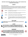
6.1.1. Servicing of batteries should be performed or supervised by personnel knowledgeable of
batteries and the required precautions. Keep unauthorized personnel away from batteries.
When installing or replacing batteries, install or replace with the same number and type.
6.1.2. Do not dispose of battery or batteries in a fire. The battery may explode.
6.1.3. Do not open or mutilate the battery or batteries. Released electrolyte is harmful to the skin and
eyes and may be toxic.
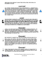
6.1.4. A battery can present a risk of electrical shock and high short circuit current. The following
precautions should be observed when working on batteries:
6.1.4.1. Remove watches, rings, or other metal objects.
6.1.4.2. Use tools with insulated handles.
6.1.4.3. Wear rubber gloves and boots.
6.1.4.4. Do not lay tools or metal parts on top of batteries.
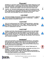
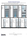
6.1.5. Make sure the proper polarity is observed. DC bus should be between 240 and 272 Vdc
as tested at the top of the Battery Circuit Breaker-CB2 (Refer to Figure 12a—System
Component Layout).
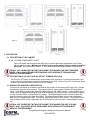
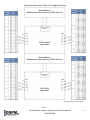
6.1.6. All battery are housed in the UPS unit in the Single Phase inverter. Internal Battery Pack’s jumpers
are provided by the factory. When connecting batteries, you must connect the individual batteries
into string (s). Please see battery layout on the inside door of your inverter unit. Note: Layout illustrate the number of batteries in a string, number of batteries per shelf, and their jumpers placements (i.e., negative of first battery to positive of the second battery, negative of the second battery
to positive of third battery, etc.).
After creating each string of batteries, ensure that each string consist of the number of batteries
indicated by the battery layout and the measured voltage from the first to the last battery is within
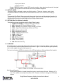
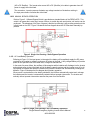
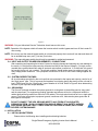
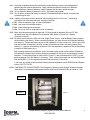
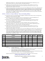
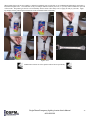
tolerance. Connect the jumper on shelf (refer to Figure 7), that is identified as B1-POS (+) to the
positive terminal of the first battery in the string. Then, connect the jumper (on the last shelf) identified as B20-NEG (-) to the negative terminal of the last battery in the string.
If you have any further questions about battery connections please contact DSPM Service Department at 1(877)377-6769.
6.1.A. CHARGING OF THE BATTERIES: The Emergency Lighting Inverter System charges its battery
whenever it is connected to utility power and the input circuit breakers (CB1) is turned on. Dis-
B1-POS (+)
B20-NEG (-)
Figure 7
Single Phase Emergency Lighting Inverter User’s Manual
#018-3000-00
21