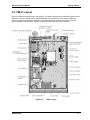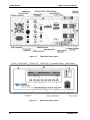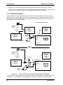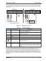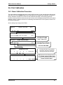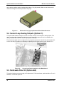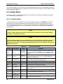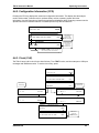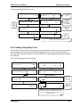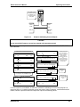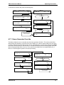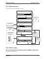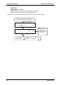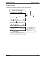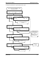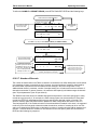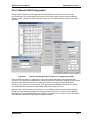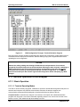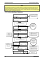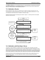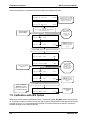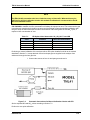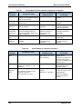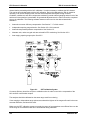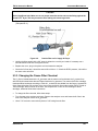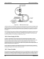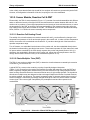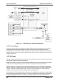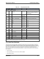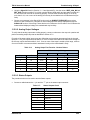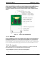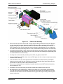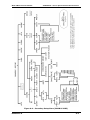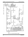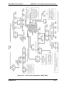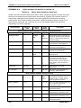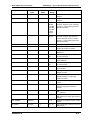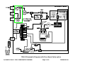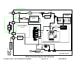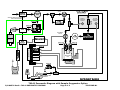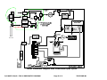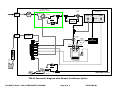
1
INSTRUCTION MANUAL
TML41
NITROGEN OXIDES ANALYZER
35 INVERNESS DRIVE EAST
ENGLEWOOD, CO 80112
USA
TOLL-FREE SUPPORT:
FAX:
TEL:
E-MAIL:
WEBSITE:
Copyright 2009
Teledyne Monitor Labs, Inc.
800-846-6062
303-799-4853
303-792-3300
[email protected]
http://www.teledyne-ml.com
044100102
REV. B15
July 2009
THIS PAGE IS INTENTIONALLY LEFT BLANK
TML41 Instruction Manual
Safety Messages
SAFETY MESSAGES
Your safety and the safety of others is very important. We have provided many important safety messages in
this manual. Please read these messages carefully.
A safety message alerts you to potential hazards that could hurt you or others. Each safety message is
associated with a safety alert symbol. These symbols are found in the manual and inside the instrument. The
definition of these symbols is described below:
GENERAL SAFETY HAZARD: Refer to the instructions for details on the
specific hazard.
CAUTION: Hot Surface Warning.
CAUTION: Electrical Shock Hazard.
TECHNICIAN SYMBOL: All operations marked with this symbol are to be
performed by qualified maintenance personnel only.
CAUTION
The analyzer should only be used for the purpose and in the manner described in this manual. If you use
the analyzer in a manner other than that for which it was intended, unpredictable behavior could ensue
with possible hazardous consequences.
This analyzer is for indoor use only and for altitudes up to 2000 m (6500 ft).
05294 Rev A6
i
Table of Contents
TML41 Instruction Manual
TABLE OF CONTENTS
SAFETY MESSAGES ..................................................................................................................................................... I
TABLE OF CONTENTS ................................................................................................................................................ II
LIST OF FIGURES ..................................................................................................................................................... VII
LIST OF TABLES ........................................................................................................................................................ IX
LIST OF APPENDICES ............................................................................................................................................... XI
1. TML41 DOCUMENTATION ....................................................................................................................................... 1
1.1. Available Documentation .................................................................................................................................... 1
1.2. Manual Structure ................................................................................................................................................ 1
1.3. How to use this Instruction Manual ..................................................................................................................... 3
2. SPECIFICATIONS, APPROVALS AND WARRANTY .............................................................................................. 5
2.1. TML41 Operating Specifications ........................................................................................................................ 5
2.2. EPA Equivalency Designation ............................................................................................................................ 6
2.3. CE Mark Compliance ......................................................................................................................................... 7
2.4. Warranty Procedure ........................................................................................................................................... 7
3. GETTING STARTED ................................................................................................................................................. 9
3.1. Unpacking and Initial Setup ................................................................................................................................ 9
3.2. TML41 Layout .................................................................................................................................................. 11
3.3. Pneumatic Connections ................................................................................................................................... 13
3.3.1. Span Gas Defined .................................................................................................................................... 14
3.3.2. Zero Gas Defined ..................................................................................................................................... 15
3.4. Electrical Connections ...................................................................................................................................... 17
3.4.1. Power Connection .................................................................................................................................... 17
3.4.2. Analog Output Connections ...................................................................................................................... 17
3.4.3. Ethernet Connection and Configuration .................................................................................................... 20
3.5. Initial Operation ................................................................................................................................................ 20
3.5.1. Startup ...................................................................................................................................................... 20
3.5.2. Warm-Up .................................................................................................................................................. 21
3.5.3. Warning Messages ................................................................................................................................... 22
3.5.4. Functional Check ...................................................................................................................................... 23
3.6. First Calibration ................................................................................................................................................ 27
3.6.1. Basic Calibration Procedure ..................................................................................................................... 27
3.6.2. Interferences for NOX Measurements ....................................................................................................... 30
4. FREQUENTLY ASKED QUESTIONS & GLOSSARY ............................................................................................. 31
4.1. Frequently Asked Questions ............................................................................................................................ 31
4.2. Glossary ........................................................................................................................................................... 32
5. OPTIONAL HARDWARE AND SOFTWARE .......................................................................................................... 35
5.1. External Pumps (Option 10) ............................................................................................................................. 35
5.2. Rack Mount Kits (Options 20-23) ..................................................................................................................... 35
5.3. Carrying Strap Handle (Option 29) ................................................................................................................... 35
5.4. Current Loop Analog Outputs (Option 41) ........................................................................................................ 36
5.5. Particulate Filter Kit (Option 42A) ..................................................................................................................... 36
5.6. Calibration Valve Options ................................................................................................................................. 37
5.6.1. Zero/Span Valves (Option 50) .................................................................................................................. 37
5.6.2. Internal Zero/Span (IZS) (Option 51) ........................................................................................................ 37
5.6.3. IZS Permeation Tubes (Options 53 & 55) ................................................................................................. 38
5.7. Scrubbers and Expendables ............................................................................................................................ 39
5.7.1. Charcoal Scrubber (Option 64A) .............................................................................................................. 39
5.7.2. Charcoal Refill Kit (Part# 00596) .............................................................................................................. 39
5.7.3. Zero Air Scrubber (Option 64B) ................................................................................................................ 39
5.7.4. Zero Air Scrubber Maintenance Kit (Option 43) ........................................................................................ 39
5.7.5. TML41 Expendables Kit (Option 42) ......................................................................................................... 40
5.7.6. TML41 Spare Parts Kit (Option 43)........................................................................................................... 40
5.8. Communication Options ................................................................................................................................... 40
5.8.1. RS232 Modem Cables (Options 60 and 60A) ........................................................................................... 40
5.8.2. RS-232 Multidrop (Option 62) ................................................................................................................... 40
5.8.3. Ethernet (Option 63) ................................................................................................................................. 40
5.9. Sample Gas Conditioners (Options 86 & 88).................................................................................................... 41
5.10. Additional Manual (Option 70) ........................................................................................................................ 42
5.11. Manual on CD (Option 70A) ........................................................................................................................... 42
5.12. Extended Warranty (Options 92 & 93) ............................................................................................................ 42
6. OPERATING INSTRUCTIONS ................................................................................................................................ 43
ii
05294 Rev A6
TML41 Instruction Manual
Table of Contents
6.1. Overview of Operating Modes .......................................................................................................................... 43
6.2. Sample Mode ................................................................................................................................................... 44
6.2.1. Test Functions .......................................................................................................................................... 44
6.2.2. Warning Messages ................................................................................................................................... 45
6.2.3. Calibration Functions ................................................................................................................................ 46
6.3. Calibration Mode .............................................................................................................................................. 46
6.4. Setup Mode ...................................................................................................................................................... 46
6.4.1. Password (PASS) ..................................................................................................................................... 46
6.4.2. Configuration Information (CFG) .............................................................................................................. 49
6.4.3. Clock (CLK) .............................................................................................................................................. 49
6.5. Setup - Range Configuration (RNGE) .............................................................................................................. 50
6.5.1. Physical and Analog Output Ranges ........................................................................................................ 51
6.5.2. Reporting Range Modes ........................................................................................................................... 51
6.5.3. Single Range mode (SNGL) ..................................................................................................................... 51
6.5.4. Independent Range Mode (IND) ............................................................................................................... 52
6.5.5. Auto Range Mode (AUTO) ....................................................................................................................... 54
6.5.6. Range Units .............................................................................................................................................. 54
6.5.7. Dilution Ratio ............................................................................................................................................ 55
6.6. Setup - Internal Variables (VARS) .................................................................................................................... 57
6.7. Setup - Diagnostics (DIAG) .............................................................................................................................. 59
6.7.1. Signal I/O .................................................................................................................................................. 60
6.7.2. Analog Output Step Test .......................................................................................................................... 61
6.7.3. Analog I/O Configuration .......................................................................................................................... 62
6.7.4. Test Channel Output................................................................................................................................. 70
6.7.5. Optic Test ................................................................................................................................................. 72
6.7.6. Electrical Test ........................................................................................................................................... 72
6.7.7. Ozone Generator Override ....................................................................................................................... 73
6.7.8. Flow Calibration ........................................................................................................................................ 74
6.8. Digital Inputs and Outputs ................................................................................................................................ 74
6.8.1. Status Outputs .......................................................................................................................................... 74
6.8.2. Control Inputs ........................................................................................................................................... 75
6.9. Setup - Communication Ports (COMM) ............................................................................................................ 76
6.9.1. Analyzer ID ............................................................................................................................................... 77
6.9.2. COM Port Default Settings ....................................................................................................................... 77
6.9.3. COM Port Cable Connections .................................................................................................................. 77
6.9.4. COM2 Configuration ................................................................................................................................. 78
6.9.5. DTE and DCE Communication ................................................................................................................. 78
6.9.6. COM Port Communication Modes ............................................................................................................ 78
6.9.7. COM Port Baud Rate ................................................................................................................................ 81
6.9.8. COM Port Testing ..................................................................................................................................... 81
6.9.9. Ethernet Port Configuration ...................................................................................................................... 82
6.9.10. Hessen Mode Configuration ................................................................................................................... 85
6.10. Setup - Data Acquisition System (DAS) ......................................................................................................... 86
6.10.1. iDAS Structure ........................................................................................................................................ 86
6.10.2. Configuring the iDAS .............................................................................................................................. 89
6.10.3. Remote iDAS Configuration .................................................................................................................. 103
6.11. Remote Operation of the Analyzer ............................................................................................................... 104
6.11.1. Basic Operation .................................................................................................................................... 104
6.11.2. Status Reporting ................................................................................................................................... 106
6.11.3. Remote Access by Modem ................................................................................................................... 107
6.11.4. COM Port Password Security ............................................................................................................... 108
6.11.5. sensor-e.com Remote Control Program ............................................................................................... 109
6.11.6. Additional Communications Documentation ......................................................................................... 110
7. CALIBRATION PROCEDURES ............................................................................................................................ 111
7.1. Calibration Preparations ................................................................................................................................. 111
7.1.1. Required Equipment, Supplies, and Expendables .................................................................................. 111
7.1.2. Zero Air ................................................................................................................................................... 111
7.1.3. Span Gas Standards .............................................................................................................................. 111
7.1.4. NO2 Permeation Tubes ........................................................................................................................... 112
7.1.5. Calibration Gas Traceability .................................................................................................................... 112
7.1.6. Data Recording Devices ......................................................................................................................... 112
7.1.7. NO2 Conversion Efficiency ..................................................................................................................... 112
7.2. Manual Calibration ......................................................................................................................................... 114
7.2.1. Connect Zero Air and Span Gases to the Analyzer ................................................................................ 115
7.2.2. Set Expected NO and NOX Span Gas Concentrations ........................................................................... 115
05294 Rev A6
iii
Table of Contents
TML41 Instruction Manual
7.2.3. Perform Zero/Span Calibration: .............................................................................................................. 116
7.3. Calibration Checks ......................................................................................................................................... 117
7.4. Calibration with Zero/Span Valves ................................................................................................................. 117
7.5. Calibration with IZS Option ............................................................................................................................. 118
7.6. Calibration Checks with IZS or Zero/Span Valves .......................................................................................... 121
7.7. Calibration With Independent or AUTO Ranges ............................................................................................. 122
7.7.1. Calibration in AUTO Range Mode .......................................................................................................... 122
7.7.2. Independent Range Mode ...................................................................................................................... 123
7.7.3. Calibration With Remote Contact Closures ............................................................................................ 123
7.8. Automatic Calibration (AutoCal) ..................................................................................................................... 123
7.9. Calibration Quality Analysis ............................................................................................................................ 126
8. EPA PROTOCOL CALIBRATION ......................................................................................................................... 129
8.1. Calibration of Equipment ................................................................................................................................ 129
8.2. Gas Phase Titration (GPT) ............................................................................................................................. 131
8.2.1. GPT Principle of Operation ..................................................................................................................... 131
8.2.2. GPT Calibrator Check Procedure ........................................................................................................... 131
8.2.3. Example GPT Calculation....................................................................................................................... 132
8.3. Multipoint Calibration Procedure .................................................................................................................... 133
8.3.1. Zero Calibration ...................................................................................................................................... 135
8.3.2. Span Calibration ..................................................................................................................................... 135
8.3.3. GPT NO2 Calibration .............................................................................................................................. 135
8.4. Calibration Frequency .................................................................................................................................... 136
8.5. Other Quality Assurance Procedures ............................................................................................................. 136
8.6. Summary of Quality Assurance Checks ......................................................................................................... 137
8.7. Short Calibration Checks ................................................................................................................................ 138
8.7.1. Zero/Span Check Procedures ................................................................................................................ 138
8.7.2. Precision Check ...................................................................................................................................... 139
8.7.3. Precision Check Procedure .................................................................................................................... 139
8.8. Certification of Working Standards ................................................................................................................. 139
8.8.1. Certification Procedures of Working Standards ...................................................................................... 140
8.9. References ..................................................................................................................................................... 140
9. INSTRUMENT MAINTENANCE ............................................................................................................................ 143
9.1. Maintenance Schedule ................................................................................................................................... 143
9.2. Predictive Diagnostics .................................................................................................................................... 144
9.3. Maintenance Procedures................................................................................................................................ 145
9.3.1. Changing the Sample Particulate Filter .................................................................................................. 145
9.3.2. Changing the O3 Dryer Particulate Filter ................................................................................................. 146
9.3.3. Changing the Ozone Filter Chemical ...................................................................................................... 147
9.3.4. Rebuilding the External Sample Pump ................................................................................................... 149
9.3.5. Changing the Pump and IZS Dust Filters ............................................................................................... 149
9.3.6. Changing the IZS Permeation Tube ....................................................................................................... 150
9.3.7. Changing the External Zero Air Scrubber ............................................................................................... 150
9.3.8. Changing the NO2 converter ................................................................................................................... 152
9.3.9. Cleaning the Reaction Cell ..................................................................................................................... 153
9.3.10. Cleaning or Changing Critical Flow Orifices ......................................................................................... 154
9.3.11. Checking for Light Leaks ...................................................................................................................... 156
10. THEORY OF OPERATION .................................................................................................................................. 157
10.1. Measurement Principle ................................................................................................................................. 157
10.1.1. Chemiluminescence ............................................................................................................................. 157
10.1.2. NOX and NO2 Determination ................................................................................................................. 158
10.1.3. Chemiluminescence Detection ............................................................................................................. 159
10.1.4. Auto Zero .............................................................................................................................................. 160
10.1.5. Measurement Interferences .................................................................................................................. 161
10.2. Pneumatic Operation .................................................................................................................................... 163
10.2.1. Pump and Exhaust Manifold ................................................................................................................. 163
10.2.2. Sample Gas Flow ................................................................................................................................. 164
10.2.3. Ozone Gas Air Flow.............................................................................................................................. 165
10.2.4. O3 Generator ........................................................................................................................................ 166
®
10.2.5. Perma Pure Dryer ............................................................................................................................... 167
10.2.6. Ozone Supply Air Filter ......................................................................................................................... 168
10.2.7. Ozone Scrubber ................................................................................................................................... 168
10.2.8. Flow Rate Control - Critical Flow Orifices ............................................................................................. 169
10.2.9. Pneumatic Sensors............................................................................................................................... 171
10.2.10. Dilution Manifold ................................................................................................................................. 172
10.3. Electronic Operation ..................................................................................................................................... 173
iv
05294 Rev A6
TML41 Instruction Manual
Table of Contents
10.3.1. CPU ...................................................................................................................................................... 174
10.3.2. Sensor Module, Reaction Cell & PMT .................................................................................................. 176
10.3.3. Pneumatic Sensor Board ...................................................................................................................... 179
10.3.4. Relay Board .......................................................................................................................................... 179
10.3.5. Motherboard ......................................................................................................................................... 180
10.3.6. Power Supply/ Circuit Breaker .............................................................................................................. 182
10.3.7. Communications Interface .................................................................................................................... 183
10.4. Software Operation ...................................................................................................................................... 186
10.4.1. Adaptive Filter ....................................................................................................................................... 186
10.4.2. Calibration - Slope and Offset ............................................................................................................... 187
10.4.3. Temperature/Pressure Compensation (TPC) ....................................................................................... 187
10.4.4. NO2 Converter Efficiency Compensation .............................................................................................. 188
10.4.5. Internal Data Acquisition System (iDAS) .............................................................................................. 189
11. TROUBLESHOOTING & REPAIR....................................................................................................................... 191
11.1. General Troubleshooting .............................................................................................................................. 191
11.1.1. Warning Messages ............................................................................................................................... 191
11.1.2. Fault Diagnosis with Test Functions ..................................................................................................... 192
11.1.3. Using the Diagnostic Signal I/O Function ............................................................................................. 193
11.1.4. Status LED’s ......................................................................................................................................... 194
11.2. Gas Flow Problems ...................................................................................................................................... 197
11.2.1. Zero or Low Flow Problems .................................................................................................................. 198
11.2.2. High Flow.............................................................................................................................................. 199
11.2.3. Sample Flow is Zero or Low But Analyzer Reports Correct Flow ......................................................... 199
11.3. Calibration Problems .................................................................................................................................... 200
11.3.1. Negative Concentrations ...................................................................................................................... 200
11.3.2. No Response ........................................................................................................................................ 201
11.3.3. Unstable Zero and Span ....................................................................................................................... 201
11.3.4. Inability to Span - No SPAN Key .......................................................................................................... 201
11.3.5. Inability to Zero - No ZERO Key ........................................................................................................... 202
11.3.6. Non-Linear Response ........................................................................................................................... 202
11.3.7. Discrepancy between Analog Output and Display ................................................................................ 203
11.3.8. Discrepancy between NO and NOX slopes ........................................................................................... 203
11.4. Other Performance Problems ....................................................................................................................... 203
11.4.1. Excessive noise .................................................................................................................................... 204
11.4.2. Slow Response ..................................................................................................................................... 204
11.4.3. AutoZero Warnings ............................................................................................................................... 204
11.5. Subsystem Checkout.................................................................................................................................... 205
11.5.1. Simple Vacuum Leak and Pump Check ............................................................................................... 205
11.5.2. Detailed Pressure Leak Check ............................................................................................................. 205
11.5.3. Performing a Sample Flow Check ........................................................................................................ 206
11.5.4. AC Power Configuration ....................................................................................................................... 206
11.5.5. DC Power Supply ................................................................................................................................. 207
11.5.6. I2C Bus ................................................................................................................................................. 207
11.5.7. Keyboard / Display Interface ................................................................................................................. 208
11.5.8. Relay Board .......................................................................................................................................... 208
11.5.9. Motherboard ......................................................................................................................................... 208
11.5.10. CPU .................................................................................................................................................... 210
11.5.11. RS-232 Communication...................................................................................................................... 210
11.5.12. PMT Sensor ........................................................................................................................................ 211
11.5.13. PMT Preamplifier Board ..................................................................................................................... 211
11.5.14. High Voltage Power Supply ................................................................................................................ 211
11.5.15. Pneumatic Sensor Assembly .............................................................................................................. 212
11.5.16. NO2 Converter .................................................................................................................................... 213
11.5.17. O3 Generator ...................................................................................................................................... 214
11.5.18. IZS Option .......................................................................................................................................... 215
11.5.19. Box Temperature ................................................................................................................................ 215
11.5.20. PMT Temperature............................................................................................................................... 215
11.6. Repair Procedures ....................................................................................................................................... 216
11.6.1. Disk-on-Chip Replacement ................................................................................................................... 216
11.6.2. Flash Chip Replacement or Upgrade.................................................................................................... 216
11.6.3. O3 Generator Replacement .................................................................................................................. 217
11.6.4. Sample and Ozone Dryer Replacement ............................................................................................... 217
11.6.5. PMT Sensor Hardware Calibration (Factory Cal) ................................................................................. 218
11.6.6. PMT Sensor Hardware Calibration (Field Cal) ...................................................................................... 219
11.6.7. Replacing the PMT, HVPS or TEC ....................................................................................................... 220
05294 Rev A6
v
Table of Contents
TML41 Instruction Manual
11.7. Technical Assistance .................................................................................................................................... 222
12. A PRIMER ON ELECTRO-STATIC DISCHARGE............................................................................................... 223
12.1. How Static Charges are Created .................................................................................................................. 223
12.2. How Electro-Static Charges Cause Damage................................................................................................ 224
12.3. Common Myths About ESD Damage ........................................................................................................... 225
12.4. Basic Principles of Static Control .................................................................................................................. 225
12.4.1. General Rules ....................................................................................................................................... 226
12.4.2. Basic anti-ESD Procedures for Analyzer Repair and Maintenance ...................................................... 227 vi
05294 Rev A6
TML41 Instruction Manual
List of Figures
LIST OF FIGURES
Figure
Figure
Figure
Figure
Figure
Figure
Figure
Figure
Figure
Figure
Figure
Figure
Figure
Figure
Figure
Figure
Figure
Figure
Figure
Figure
Figure
Figure
Figure
Figure
Figure
Figure
Figure
Figure
Figure
Figure
Figure
Figure
Figure
Figure
Figure
Figure
Figure
Figure
Figure
Figure
Figure
Figure
Figure
Figure
Figure
Figure
Figure
Figure
Figure
Figure
Figure
Figure
3-1: 3-2: 3-3: 3-4: 3-5: 3-6: 3-7: 3-8: 3-9: 3-10: 3-11: 3-12: 5-1: 5-2: 5-3: 6-1: 6-2: 6-3: 6-4: 6-5: 6-6: 6-7: 6-8: 7-1: 7-2: 7-3: 7-4: 8-1: 9-1: 9-2: 9-3: 9-4: 9-5: 9-6: 9-7: 10-1: 10-2: 10-3: 10-4: 10-5: 10-6: 10-7: 10-8: 10-9: 10-10: 10-11: 10-12: 10-13: 10-14: 10-15: 10-16: 10-17: 05294 Rev A6
Location of Shipping Screws and Power Configuration Plug ...........................................10 TML41 Layout ............................................................................................................................11 TML41 Rear Panel Layout .......................................................................................................12 TML41 Front Panel Layout ......................................................................................................12 Basic Pneumatic Connections for Units without Valve Options ......................................14 Basic Pneumatic Connections for Units with Valve Options ............................................16 Analog Output Connector .......................................................................................................17 Status Output Connector ........................................................................................................18 Control Input Connector .........................................................................................................19 Front Panel Display during Startup Sequence ...................................................................21 TML41 Pneumatic Diagram In Standard Configuration....................................................25 TML41 Pneumatic Diagram With Options Installed...........................................................26 TML41 with Carrying Strap Handle and Rack Mount Brackets .......................................36 Current Loop Option Installed on the Motherboard ..........................................................36 TML41 Ethernet Card and Rear Panel With Ethernet Installed ......................................41 Analog Output Connector Key ...............................................................................................50 Setup for Calibrating Analog Outputs ..................................................................................66 Setup for Calibrating Current Outputs.................................................................................69 Status Output Connector ........................................................................................................75 Control Inputs with Local and External 5 V Power Supply ..............................................76 sensor-e.com Graphical User Interface for Configuring the iDAS ...............................103 iDAS Configuration Through a Terminal Emulation Program .......................................104 sensor-e.com Remote Control Program Interface ..........................................................109 Gas Supply Setup for Determination of NO2 Conversion Efficiency ............................113 Setup for Manual Calibration without Z/S valve or IZS Option ...................................115 Pneumatic Connections for Manual Calibration Checks with IZS ................................119 Setup for Manual Calibration Check with Z/S Valve or IZS Option .............................121 GPT Calibration System ........................................................................................................134 Sample Particulate Filter Assembly ....................................................................................146 Particle Filter on O3 Supply Air Dryer ................................................................................147 04419 Ozone Filter Unit ........................................................................................................148 Zero Air Scrubber Assembly ................................................................................................152 NO2 Converter Assembly ......................................................................................................153 Reaction Cell Assembly .........................................................................................................154 Critical Flow Orifice Assembly .............................................................................................156 TML41 Sensitivity Spectrum ................................................................................................158 NO2 Conversion Principle ......................................................................................................159 Reaction Cell with PMT Tube................................................................................................160 Reaction Cell during the AutoZero Cycle. .........................................................................161 External Pump Pack ...............................................................................................................164 Ozone Generator Principle....................................................................................................166 Semi-Permeable Membrane Drying Process ....................................................................167 TML41 Perma Pure® Dryer ...................................................................................................168 Flow Control Assembly & Critical Flow Orifice ..................................................................170 Vacuum Manifold, Standard Configuration .......................................................................171 Dilution Manifold .....................................................................................................................173 TML41 Electronic Block Diagram.........................................................................................174 TML41 CPU Board Annotated ...............................................................................................175 Schematic of Basic PMT Design and Functionality ..........................................................176 PMT Preamp Block Diagram .................................................................................................178 Power Distribution Block Diagram ......................................................................................183 TML41 Electronic Interface Block Diagram .......................................................................184 vii
List of Figures
Figure
Figure
Figure
Figure
Figure
Figure
Figure
Figure
Figure
Figure
Figure
viii
TML41 Instruction Manual
10-18: Keyboard and Display Interface Block Diagram ..............................................................186 10-19: Schematic of Basic Software Operation ............................................................................187 11-1: Viewing and Clearing Warning Messages..........................................................................192 11-2: Switching Signal I/O Functions ...........................................................................................194 11-3: Motherboard Watchdog Status Indicator ..........................................................................195 11-4: Relay Board PCA .....................................................................................................................196 11-5: Pressure / Flow Sensor Assembly .......................................................................................213 11-6: Pre-Amplifier Board Layout ..................................................................................................219 11-7: TML41 Sensor Assembly .......................................................................................................221 12-1: Triboelectric Charging .............................................................................................................223 12-2: Basic anti-ESD Work Station .................................................................................................226 05294 Rev A6
TML41 Instruction Manual
List of Tables
LIST OF TABLES
Table
Table
Table
Table
Table
Table
Table
Table
Table
Table
Table
Table
Table
Table
Table
Table
Table
Table
Table
Table
Table
Table
Table
Table
Table
Table
Table
Table
Table
Table
Table
Table
Table
Table
Table
Table
Table
Table
Table
Table
Table
Table
Table
Table
Table
Table
Table
Table
Table
Table
Table
Table
2-1: 3-1: 3-2: 3-3: 3-4: 3-5: 3-6: 5-1: 5-2: 5-3: 5-4: 6-1: 6-2: 6-3: 6-4: 6-5: 6-6: 6-7: 6-8: 6-9: 6-10: 6-11: 6-12: 6-13: 6-14: 6-15: 6-16: 6-17: 6-18: 6-19: 6-20: 6-21: 6-22: 6-23: 6-24: 6-25: 7-1: 7-2: 7-3: 7-4: 7-5: 8-1: 8-2: 8-3: 8-4: 9-1: 9-2: 10-1: 10-2: 10-3: 10-4: 11-1: 05294 Rev A6
TML41 Basic Unit Specifications ..............................................................................................5 Inlet / Outlet Connector Nomenclature ...............................................................................13 Analog Output Pin-Outs ..........................................................................................................18 Status Output Signals .............................................................................................................18 Control Input Signals...............................................................................................................19 Front Panel Display during System Warm-Up....................................................................22 Possible Warning Messages at Start-Up ..............................................................................23 IZS or Z/S Valve States ..........................................................................................................37 Available Permeation Source Options ..................................................................................38 Contents of Zero Air Scrubber Maintenance Kit ................................................................39 Dryer and NH3 Removal Options...........................................................................................41 Analyzer Operating modes .....................................................................................................43 Test Functions Defined............................................................................................................44 List of Warning Messages Revision C.4 ...............................................................................45 Password Levels .......................................................................................................................47 Variable Names (VARS) Revision C.4 ..................................................................................57 TML41 Diagnostic (DIAG) Functions ....................................................................................59 DIAG - Analog I/O Functions .................................................................................................62 Analog Output Voltage Ranges .............................................................................................62 Analog Output Current Loop Range .....................................................................................63 Analog Output Pin Assignments ............................................................................................63 Voltage Tolerances for Analog Output Calibration ............................................................66 Current Loop Output Calibration with Resistor ..................................................................70 Test Parameters Available for Analog Output A4 ..............................................................71 Status Output Pin Assignments.............................................................................................75 Control Input Pin Assignments ..............................................................................................76 COM1 and COM2 DB-9 Pin Assignments .............................................................................78 COM Port Communication Modes..........................................................................................79 Ethernet Status Indicators .....................................................................................................82 Front Panel LED Status Indicators for iDAS .......................................................................86 iDAS Data Channel Properties ...............................................................................................87 iDAS Data Parameter Functions ............................................................................................88 TML41 Default iDAS Configuration, Revision C.7..............................................................89 Terminal Mode Software Commands .................................................................................105 Command Types .....................................................................................................................106 Serial Interface Documents .................................................................................................110 IZS Option Valve States with CAL_ON_NO2 Turned ON ................................................119 AutoCal Modes ........................................................................................................................124 AutoCal Attribute Setup Parameters ..................................................................................124 Example Auto-Cal Sequence................................................................................................125 Calibration Data Quality Evaluation ...................................................................................127 Activity Matrix for EPA Calibration Equipment and Supplies ........................................130 Activity Matrix for Calibration Procedure ..........................................................................130 Definition of Level 1 and Level 2 Zero and Span Checks ..............................................137 Activity Matrix for Data Quality ...........................................................................................138 TML41 Preventive Maintenance Schedule .........................................................................143 Predictive Uses for Test Functions......................................................................................145 List of Interferents .................................................................................................................162 TML41 Valve Cycle Phases ...................................................................................................165 TML41 Gas Flow Rates ..........................................................................................................170 Front Panel Status LED’s ......................................................................................................185 Test Functions - Possible Causes for Out-Of-Range Values..........................................193 ix
List of Tables
Table
Table
Table
Table
Table
Table
Table
Table
x
11-2: 11-3: 11-4: 11-5: 11-6: 11-7: 12-1: 12-2: TML41 Instruction Manual
Relay Board Status LEDs ......................................................................................................197 DC Power Test Point and Wiring Color Code ....................................................................207 DC Power Supply Acceptable Levels ..................................................................................207 Relay Board Control Devices ...............................................................................................208 Analog Output Test Function - Nominal Values ...............................................................209 Status Outputs Check ...........................................................................................................209 Static Generation Voltages for Typical Activities .............................................................224 Sensitivity of Electronic Devices to Damage by ESD .....................................................224 05294 Rev A6
TML41 Instruction Manual
List of Appendices
LIST OF APPENDICES
APPENDIX A – VERSION SPECIFIC SOFTWARE DOCUMENTATION
APPENDIX A-1:TML41 Software Menu Trees
APPENDIX A-2:TML41 Setup Variables for Serial I/O
APPENDIX A-3:TML41 Warnings and Test Functions
APPENDIX A-4:TML41 Signal I/O Definitions
APPENDIX A-5:TML41 iDAS Parameters
APPENDIX A-6:Terminal Command Designators
APPENDIX A-7:Setting up Communications
APPENDIX B: TML41 SPARE PARTS
APPENDIX C: REPAIR QUESTIONNAIRE MODEL TML41
APPENDIX D: ELECTRONIC SCHEMATICS
USER NOTES:
05294 Rev A6
xi
THIS PAGE IS INTENTIONALLY LEFT BLANK
TML41 Instruction Manual
TML41 Documentation
1. TML41 DOCUMENTATION
1.1. Available Documentation
Thank you for purchasing the TML41 Nitrogen Oxides Analyzer! The documentation for this instrument is
available in different formats:
•
Printed format, part number 044100100
•
Electronic format on a CD-ROM, part number 044100200
The electronic manual is in Adobe® Systems Inc. “Portable Document Format” (PDF). The Adobe®
Acrobat Reader® software, which is necessary to view these files, can be downloaded for free from the
internet at http://www.adobe.com/.
The electronic version of the manual has many advantages:
•
Keyword and phrase search feature
•
Figures, tables and internet addresses are linked so that clicking on the item will display the
associated feature or open the website.
•
A list of sections and thumbnails of each page are displayed to the left of the text.
•
Entries in the table of contents are linked to the corresponding locations in the manual.
•
Ability to print sections (or all) of the manual
Additional documentation for the TML41 Nitrogen Oxides Analyzer is available from Teledyne
Instruments’ website at http://www.teledyne-ml.com
•
sensor-e.com software manual, part number 03945
•
Multi-drop manual, part number 02179
•
DAS manual, part number 02837.
•
Ethernet configuration document, part number 04324.
Other documentation may be added to the website in the future.
1.2. Manual Structure
1.0 Table of Contents:
Outlines the contents of the manual in the order the information is presented. This is a good overview of
the topics covered in the manual. There is also a list of appendices, figures and tables. In the electronic
version of the manual, clicking on any of these table entries automatically views that section.
05294 Rev A6
1
TML41 Documentation
TML41 Instruction Manual
2.0 Specifications and Warranty
A list of the analyzer’s performance specifications, a description of the conditions and configuration under
which EPA equivalency was approved and T-ML’s warranty policy.
3.0 Getting Started
Concise instructions for setting up, installing and running your analyzer for the first time.
4.0 FAQ & Glossary:
Answers to the most frequently asked questions about operating the analyzer and a glossary of
acronyms and technical terms.
5.0 Optional Hardware & Software
A description of optional equipment to add functionality to your analyzer.
6.0 Operation Instructions
Step by step instructions for operating the analyzer.
7.0 Calibration Procedures
General information and step by step instructions for calibrating your analyzer.
8.0 EPA Protocol Calibration
Specific information regarding calibration requirements for analyzers used in EPA-regulated monitoring
applications.
9.0 Instrument Maintenance
Description of preventative maintenance procedures that should be regularly performed on you
instrument to assure good operating condition. This includes information on using the iDAS to predict
possible component failures before they happen.
10.0
Theory of Operation
An in-depth look at the various principals by which your analyzer operates as well as a description of how
the various electronic, mechanical and pneumatic components of the instrument work and interact with
each other. A close reading of this section is invaluable for understanding the instrument’s operation.
11.0
Troubleshooting & Repair
This section includes pointers and instructions for diagnosing problems with the instrument, such as
excessive noise or drift, as well as instructions on performing repairs of the instrument’s major
subsystems.
2
05294 Rev A6
TML41 Instruction Manual
TML41 Documentation
12.0 Primer on Electro-static Discharge
This section describes how static electricity occurs, why it is a significant concern and how to avoid it.
The effects of ESD can impact the reliability and accuracy of your analyzer.
Appendices
For easier access and better updating, some information has been separated out of the manual and
placed in a series of appendices at the end of this manual. These include version-specific software menu
trees, warning messages, definitions of iDAS & serial I/O variables as well as spare part listings, repair
questionnaire, interconnect drawing, detailed pneumatic and electronic schematics.
1.3. How to use this Instruction Manual
Throughout this manual, words printed in capital, bold letters, such as SETUP or ENTR represent
messages as they appear on the analyzer’s front panel display.
The flowcharts in this manual contain typical representations of the analyzer’s display during the
described operations. These representations are not necessarily exact and may differ slightly from the
actual display of your instrument.
NOTE:
Warnings and special notes are called out in bold, centered frames such as this one.
Cautionary notes with special symbols such as this one may appear throughout
the manual indicating hazardous operations requiring either trained technical
personnel or particular attention.
05294 Rev A6
3
TML41 Documentation
TML41 Instruction Manual
USER NOTES:
4
05294 Rev A6
TML41 Instruction Manual
Specifications, Approvals and Warranty
2. SPECIFICATIONS, APPROVALS AND WARRANTY
2.1. TML41 Operating Specifications
Table 2-1:
TML41 Basic Unit Specifications
Min/Max Range
(Physical Analog Output)
Min: 0-50 ppb
Max: 0-20 ppm
Measurement Units
ppb, ppm, µg/m3, mg/m3 (user selectable)
Zero Noise
1
≤0.2 ppb (RMS)
Span Noise1
≤0.5% of reading above 50 ppb or 0.2 ppm, whichever is greater
Lower Detectable Limit
2
0.4 ppb
Zero Drift (24 hours)
≤0.5 ppb (at constant temperature and voltage.)
Zero Drift (7 days)
1 ppb (at constant temperature and voltage.)
Span Drift (7 Days)
≤0.5% of full Scale (at constant temperature and voltage.)
Linearity
≤1% of full scale
Precision
≤0.5% of reading
Lag Time1
Rise/Fall Time
20 s
1
95% in <60 s
Sample Flow Rate
500 cm3/min. ± 10%
Temperature Range
5 - 40 °C operating and EPA equivalency
Humidity Range
0-95% RH non-condensing
Dimensions H x W x D
18 cm x 43 cm x 61 cm (7" x 17" x 23.6")
Weight, Analyzer
18 kg (40 lbs)
Weight, Ext Pump Pack
7 kg (16 lbs)
AC Power Rating
100 V, 50/60 Hz (3.25A);
115 V, 60 Hz (3.0 A);
220 - 240 V, 50/60 Hz (2.5 A)
Power, Ext Pump
100 V, 50/60 Hz (3.25A); 115 V, 60 Hz (3.0 A);
220 - 240 V, 50/60 Hz (2.5 A)
Environmental
Installation category (over-voltage category) II; Pollution degree 2
Analog Outputs
4 outputs
Analog Output Ranges
All Outputs: 0.1 V, 1 V, 5 V or 10 V (user selectable)
Three outputs convertible to 4-20 mA isolated current loop.
All Ranges with 5% under/over range
Analog Output Resolution
1 part in 4096 of selected full-scale voltage (12 bit)
Status Outputs
8 Status outputs from opto-isolators, 7 defined, 1 spare
Control Inputs
6 Control inputs, 4 defined, 2 spare
Serial I/O
1 RS-232; 1 RS-485 or RS-232 (configurable)
Communication speed: 300 - 115200 baud (user selectable)
Certifications
USEPA: Reference Method Number RFNA 1194-099
CE: EN61326 (1997 w/A1: 98) Class A, FCC Part 15 Subpart B Section 15.107
Class A, ICES-003 Class A (ANSI C63.4 1992) & AS/NZS 3548 (w/A1 & A2; 97)
Class A.
1
2
As defined by the USEPA.
Defined as twice the zero noise level by the USEPA.
05294 Rev A6
5
Specifications, Approvals and Warranty
TML41 Instruction Manual
2.2. EPA Equivalency Designation
The TML41 Analyzer is designated as Reference Method Number RFNA-1194-099 (same designation as
model M200A) as per 40 CFR Part 53 when operated under the following conditions:
•
Range: Any full-scale range between 0-0.05 and 0-1.0 ppm (parts per million).
•
Ambient temperature range of 5 to 40 oC.
•
Line voltage range of 105-125 VAC or 220-240 VAC, at 50 or 60 Hz.
•
Equipped with PTFE filter element in the internal filter assembly.
•
Equipped with ozone supply air filter
External vacuum pump capable of 10 in-Hg-A at 2 standard liters per minute (slpm) or better.
Software settings:
Dynamic span
Dynamic zero
Cal-on-NO2
Dilution factor
Temp/Pressure compensation
AutoCal
Independent range
Auto-range
Converter efficiency
OFF
OFF
OFF
OFF
ON
ON or OFF
ON or OFF
ON or OFF
Acceptable values of 0.96 to 1.02
Under the designation, the analyzer may be operated with or without the following optional equipment:
•
Rack mount with or without slides.
•
Rack mount for external pump.
•
Zero/span valve options.
•
Nafion-type permeation sample gas conditioner
•
Internal zero/span (IZS) option with:
•
NO2 permeation tube - 0.4ppm at 0.7 liter per minute; certified/uncertified.
•
NO2 permeation tube - 0.8 ppm at 0.7 liter per minute; certified/uncertified.
Under the designation, the IZS option cannot be used as the source of calibration.
•
4-20mA isolated analog outputs.
•
Status outputs.
•
Control inputs.
•
RS-232 output.
•
Ethernet communications option
6
05294 Rev A6
TML41 Instruction Manual
Specifications, Approvals and Warranty
2.3. CE Mark Compliance
The Teledyne Instruments Nitrogen Oxides Analyzers TML41, TML41H and TML41M were tested and
found to be fully compliant with:
EN61326 (1997 w/A1: 98) Class A, FCC Part 15 Subpart B Section 15.107 Class A, ICES-003 Class A
(ANSI C63.4 1992) & AS/NZS 3548 (w/A1 & A2; 97) Class A.
Tested on January 02-06, 2003 at CKC Laboratories, Inc., Report Number CE03-005.
The Teledyne Instruments Nitrogen Oxides Analyzers TML41, TML41H and TML41M were tested and
found to be fully compliant with:
EN61010-1 (2001)
Tested on January 20-27, 2003.
2.4. Warranty Procedure
•
•
Customer shall notify TML of a defect within the warranty period and request a return
authorization number and designated TML repair facility. Customer shall return the defective part
or parts to the designated TML Customer Service Facility as set forth below, freight prepaid by
the customer. TML will prepay the return freight.
•
TML will notify the customer of TML’s decision to repair or replace the defective part and the
expected shipment date.
At the customer’s request, TML may elect to repair defective product(s) located in North America on
site, in which case travel expenses, travel time, and related expenses incurred by TML personnel
(excluding repair time) shall be paid by the customer.
Teledyne Monitor Labs Service Response Center 1-800-846-6062 www.teledyne-ml.com
35 Inverness Drive East, Englewood, Colorado 80112-5189 USA
Tel: 303-792-3300, Fax: 303-799-4853
05294 Rev A6
7
Specifications, Approvals and Warranty
TML41 Instruction Manual
USER NOTES:
8
05294 Rev A6
TML41 Instruction Manual
Getting Started
3. GETTING STARTED
3.1. Unpacking and Initial Setup
CAUTION
The TML41 weighs about 17 kg (40 pounds) without options installed. To avoid personal injury,
we recommend using two persons to lift and carry the analyzer.
Inspect the received packages for external shipping damage. If damaged, please advise the shipper first,
then T-ML.
Included with your analyzer is a printed record (Form number 04490) of the final performance
characterization performed on your instrument at the factory. This record is an important quality
assurance and calibration record for this instrument. It should be placed in the quality records file for this
instrument.
•
Carefully remove the top cover of the analyzer and check for internal shipping damage.
•
Remove the set screw located in the top, center of the rear panel.
•
Remove the screws fastening the top cover to the unit (four per side).
•
Lift the cover straight up.
CAUTION
Printed Circuit Assemblies (PCA) are static sensitive. Electrostatic discharges, too small to be felt
by humans, are large enough to destroy sensitive circuits.
Before touching a PCA, fasten a properly installed grounding strap to your wrist or touch a bare
metal part of the chassis to discharge any electrostatic potential.
Never disconnect electronic circuit boards, wiring harnesses or electronic subassemblies while
the unit is under power.
Do not position the equipment so that it is difficult to operate the disconnecting device.
•
Inspect the interior of the instrument to make sure all circuit boards and other components are in
good shape and properly seated.
•
Check the connectors of the various internal wiring harnesses and pneumatic hoses to make sure
they are firmly and properly seated.
•
Verify that all of the optional hardware ordered with the unit has been installed. These are checked
on the paperwork (Form 04490) accompanying the analyzer.
•
Once you have determined that no shipping damage exists and the unit includes all expected
hardware options, remove three, red colored shipping screws from the bottom of the chassis, shown
in Figure 3-1.
05294 Rev A6
9
Getting Started
Figure 3-1:
TML41 Instruction Manual
Location of Shipping Screws and Power Configuration Plug
NOTE
Save these shipping screws and re-install them whenever the unit is shipped.
A certain ventilation clearance is required for the operation of the analyzer:
Area
Minimum required clearance
Back of the instrument
10 cm / 4 inches
Sides of the instrument
2.5 cm / 1 inch
Above and below the instrument
2.5 cm / 1 inch
Various rack mount kits are available for this analyzer. See Section 5 of this manual for more
information.
10
05294 Rev A6
TML41 Instruction Manual
Getting Started
3.2. TML41 Layout
Figure 3-2 shows a top-down view of the analyzer. The shown configuration includes the Ethernet board,
IZS option, zero-air scrubber and an additional sample dryer. See Section 5 for optional equipment.
Figure 3-3 shows the rear panel configuration with optional zero-air scrubber mounted to it and two
optional fittings for the IZS option. Figure 3-4 shows the front panel layout of the analyzer.
Figure 3-2:
05294 Rev A6
TML41 Layout
11
Getting Started
12
TML41 Instruction Manual
Figure 3-3:
TML41 Rear Panel Layout
Figure 3-4:
TML41 Front Panel Layout
05294 Rev A6
TML41 Instruction Manual
Getting Started
3.3. Pneumatic Connections
Sample and calibration gases should only come into contact with PTFE (Teflon), FEP, glass or stainless
steel materials. Figure 3-5 and Figure 3-6 illustrate the most common configurations for gas supply and
exhaust lines to the TML41 Analyzer. Appendix D contains more detailed pneumatic flow diagrams for
the analyzer and its various (pneumatically related) options.
CAUTION
To prevent dust from getting into the analyzer, it was shipped with small plugs inserted into each
of the pneumatic fittings on the rear panel. Make sure that all dust plugs are removed before
attaching exhaust and supply gas lines.
Please refer to Figure 3-3 for pneumatic connections at the rear panel and Table 3-1 for nomenclature.
Table 3-1:
Inlet / Outlet Connector Nomenclature
Rear Panel Label
Function
Sample
Connects the sample gas to the analyzer. When operating the analyzer without
zero span option, this is also the inlet for any calibration gases.
Exhaust
Connects the exhaust of the analyzer with the external vacuum pump.
Span
On Units with zero/span valve or IZS option installed, this port connects the
external calibration gas to the analyzer.
Zero Air
On Units with zero/span valve or IZS option installed, this port connects the zero
air gas or the zero air cartridge to the analyzer.
•
Attach a sample inlet line to the sample inlet port. Ideally, the pressure of the sample gas should be
equal to ambient atmospheric pressure.
•
In applications where the sample gas is received from a pressurized manifold, a vent must be
provided to equalize the sample gas with ambient atmospheric pressure before it enters the analyzer.
The vented gas needs to be routed outside the immediate area or shelter surrounding the instrument.
CAUTION
Maximum pressure of any gas at the sample inlet should not exceed 1.5 in-Hg above ambient
pressure and ideally should equal ambient atmospheric pressure.
CAUTION
The exhaust from the external pump needs to be vented outside the immediate
area or shelter surrounding the instrument using a maximum of 10 meters of 1/4”
PTFE tubing.
05294 Rev A6
13
Getting Started
TML41 Instruction Manual
•
Attach the 1/4" exhaust line to the exhaust port of the analyzer and to the inlet port of the pump.
•
Attach zero air and span gas supply lines as appropriate (Figure 3-5 and Figure 3-6) to the rear panel
(Figure 3-3). For this type of analyzer, zero air and span gas are defined as follows.
3.3.1. Span Gas Defined
Span gas is defined as a gas specifically mixed to match the chemical composition of the type of gas
being measured at near full scale of the desired measurement range. To measure NOX with the TML41
NOX Analyzer, it is recommended that you use a span gas with an NO concentration equal to 80% of the
measurement range for your application.
No Valve Options Installed
Calibrated
NO gas
Source of
SAMPLE gas
MODEL 700 Gas
Dilution
Calibrator
(high
concentration)
removed
during
calibration
(with Ozone generator
option)
MODEL 701
Zero Air
Generator
VENT
Sample
Exhaust
Pump
Span
MODEL
TML41
Zero Air
OR
Calibrated
NO gas
Source of
SAMPLE gas
(At span gas
concentration)
removed
during
calibration
Needle valve to
control flow
MODEL 701
Zero Air
Generator
Valve
Sample
Exhaust
VENT
Span
MODEL
TML41
Pump
Zero Air
Figure 3-5:
Basic Pneumatic Connections for Units without Valve Options
For example, if the measurement is NOX in ambient air between 0 and 500 ppb, an appropriate span gas
would be NO in air at 400 ppb NO concentration (80% of maximum range). Even though NO gas in
14
05294 Rev A6
TML41 Instruction Manual
Getting Started
nitrogen could be used as a span gas, the matrix of the balance gas is different and may cause
interference problems or yield incorrect calibrations. The same applies to gases that contain high
concentrations of other compounds (for example, CO2 or H2O). The span gas should match all
concentrations of all gases of the measured medium as closely as possible.
Cylinders of calibrated NO gas traceable to NIST-standard reference materials specifications (also referred to
as EPA protocol calibration gases) are commercially available.
Some applications, such as EPA monitoring, require a multipoint calibration where span gases of
different concentrations are needed. We recommend using an NO gas of higher concentration combined
with a gas dilution calibrator such as a T-ML Model 700. This type of calibrator mixes a high
concentration gas with zero air (both supplied externally) to accurately produce span gas of the desired
concentration. Linearity profiles can be automated with this model and run unattended overnight. The
dynamic range of the M700 is about 0.1 to 0.001 times the original span concentration.
If a dynamic dilution system such as the T-ML model 700 is used to dilute high concentration gas
standards to low, ambient concentrations, ensure that the NO concentration of the reference gas
matches the dilution range of the calibrator. Choose the NO gas concentration such that the dynamic
dilution system operates in its mid-range and not at the extremes of its dilution capabilities. For example,
a dilution calibrator with 10-10000 dilution ratio will not be able to accurately dilute a 5000 ppm NO gas to
a final concentration of 500 ppb, as this would operate at the very extreme dilution setting. A 100 ppm NO
gas in nitrogen is much more suitable to calibrate the TML41 analyzer (dilution ratio of 222, in the midrange of the system’s capabilities).
3.3.2. Zero Gas Defined
Zero air or zero calibration gas is defined as a gas that is similar in chemical composition to the
measured medium but without the gas to be measured by the analyzer, in this case NO and NO2. If your
analyzer is equipped with an IZS or external zero air scrubber option, it is capable of creating zero air
from ambient air. However, if your application is not a measurement in ambient air, the zero calibration
gas should be matched to the matrix of the measured medium. Pure nitrogen could be used as a zero
gas for applications where NOX is measured in nitrogen.
For analyzers without zero air options, a zero air generator such as the T-ML Model 701 can be used.
Please visit the company website for more information.
If your analyzer is equiped with either the zero/span valve option (Option 50) or the internal zero/span
option (Option 51), the pneumatic connections should be made as shown in Figure 3-6 (see also
Appendix D for detailed diagram).
05294 Rev A6
15
Getting Started
Figure 3-6:
TML41 Instruction Manual
Basic Pneumatic Connections for Units with Valve Options
Once the appropriate pneumatic connections have been made, check all pneumatic fittings for leaks
using the procedures defined in Section 11.5.
WARNING
Gas flow must be maintained at all times for units with IZS Options installed. The IZS option
includes a permeation tube which emits NO2. Insufficient gas flow can build up NO2 to levels that
will damage the instrument. Remove the permeation device when taking the analyzer out of
operation.
16
05294 Rev A6
TML41 Instruction Manual
Getting Started
3.4. Electrical Connections
Refer to Figure 3-3 for the location of the rear panel electrical and pneumatic connections.
3.4.1. Power Connection
Attach the power cord to the analyzer and plug it into a power outlet capable of carrying at least 10 A
current at your AC voltage and that it is equipped with a functioning earth ground.
The TML41 analyzer can be configured for both 100-130 V and 210-240 V at either 50 or 60 Hz., To
avoid damage to your analyzer, make sure that the AC power voltage matches the voltage indicated on
the rear panel serial number label and that the frequency is between 47 and 63 Hz. Refer to Figure 3-1 to
locate and identify the power configuration plug if necessary.
If you need to reconfigure your analyzer for one of the other voltage ranges, contact the factory for an
optional power configuration jumper (shown in Figure 3-1)
CAUTION
The correct voltage and frequency needs to be supplied to the analyzer as listed on
the label on the rear panel of the instrument.
Power connections must have a functioning ground connection.
3.4.2. Analog Output Connections
Attach a strip chart recorder and/or data-logger to the appropriate contacts of the analog output
connecter on the rear panel of the analyzer.
A1
+
-
Figure 3-7:
ANALOG OUT
A2
A3
+
+
-
A4
+
-
Analog Output Connector
Output channels A1, A2 and A3 are assigned to the NOX, NO and NO2 concentration signals of the
analyzer. The output labeled A4 can be set by the user for output of any test parameter accessible
through the <TST TST> keys on the front panel display. Section 6.7.4 describes how to change that
setting.
Optional current loop outputs are available for analog output channels A1-A3. Pin-outs for the analog
output connector at the rear panel of the instrument are listed in Table 3-2.
The default analog output voltage setting of the TML41 is 0 - 5 VDC with a range of 0-500 ppb. To
change these settings, see Sections 6.5 and 6.7.3.
05294 Rev A6
17
Getting Started
TML41 Instruction Manual
Table 3-2:
Analog Output Pin-Outs
Pin
Analog Output
Data Type
Voltage Signal
Current Signal
1
2
3
4
5
6
7
8
A1
NOX
A2
NO
A3
NO2
A4
Test Channel
V Out
Ground
V Out
Ground
V Out
Ground
V Out
Ground
I Out +
I Out I Out +
I Out I Out +
I Out not available
not available
If you wish to utilize the analyzer’s status outputs to interface with a device that accepts logic-level digital
inputs, such as programmable logic controller (PLC) chips, you can access them through a 12 pin
connector on the analyzer’s rear panel labeled STATUS.
STATUS
Figure 3-8:
Table 3-3:
Pin #
Status
D
+
FOR PINS 1-8
8
EMITTER BUS
7
LOW SPAN
6
DIAGNOSTIC
MODE
5
SPAN CAL
4
ZERO CAL
3
HIGH RANGE
2
CONC VALID
SYSTEM OK
1
Status Output Connector
Status Output Signals
Condition (ON = Conducting)
1
SYSTEM OK
ON if no faults are present.
2
CONC VALID
ON if concentration measurement (NO, NO2 or NOx) is valid.
OFF any time the hold-off feature is active.
3
HIGH RANGE
ON if unit is in high range of the Auto Range Mode.
4
ZERO CAL
ON whenever the instrument is in ZERO point calibration mode.
5
SPAN CAL
ON whenever the instrument is in SPAN point calibration mode.
6
DIAG MODE
ON whenever the instrument is in diagnostic mode.
7
Unused
8
Unused
D
EMITTER BUS
The emitters of the transistors on pins 1-8 are tied together.
Unused
+
DC POWER
+ 5 VDC, 300 mA (combined rating with Control Output, if used).
Digital Ground
The ground level from the analyzer’s internal DC power supplies
If you wish to use the analyzer to remotely activate the zero and span calibration modes, several digital
control inputs are provided through a 10-pin connector labeled CONTROL IN on the analyzer’s rear
panel.
18
05294 Rev A6
TML41 Instruction Manual
Getting Started
There are two methods for energizing the control inputs. The internal +5V available from the pin labeled
“+” is the most convenient method. However, if full isolation is required, an external 5 VDC power supply
should be used.
CONTROL IN
D
E
F
U
+
A
B
C
-
Figure 3-9:
Table 3-4:
Status Definition
E
F
U
+
5 VDC Power
Supply
+
External Power Connections
Local Power Connections
Input #
D
SPAN CAL
C
ZERO CAL
B
SPAN CAL
ZERO CAL
A
CONTROL IN
Control Input Connector
Control Input Signals
ON Condition
A
REMOTE ZERO CAL
The analyzer is placed in Zero Calibration mode. The mode field of
the display will read ZERO CAL R.
B
REMOTE SPAN CAL
The analyzer is placed in low span calibration mode as part of
performing a low span (midpoint) calibration. The mode field of the
display will read LO CAL R.
C
SPARE
D
SPARE
E
SPARE
F
SPARE
Digital Ground
The ground level from the analyzer’s internal DC power supplies
(same as chassis ground).
U
External Power input
Input pin for +5 VDC required to activate pins A - F.
+
5 VDC output
Internally generated 5V DC power. To activate inputs A - F, place a
jumper between this pin and the “U” pin. The maximum amperage
through this port is 300 mA (combined with the analog output supply,
if used).
If you wish to utilize one of the analyzer’s two serial ports, attach the serial cable that is included with the
analyzer to the COM1 serial port on the rear panel. Connect the other end to a serial port on your
computer and set the computer serial port to 115000 baud transfer speed, 8 data bits, no parity, 1 stop bit
and Xon/Xoff flow control. Use the sensor-e.com remote control software that was included with the
analyzer to connect to the instrument or use any terminal emulation program. Refer to Section 6.9 of this
manual for instructions on configuration and usage of the serial port, Section 6.11 for remote operation of
the analyzer.
05294 Rev A6
19
Getting Started
TML41 Instruction Manual
3.4.3. Ethernet Connection and Configuration
If your TML41 is equipped with an Ethernet option (described in Section 5.8.3), the analyzer needs to be
configured to match the network settings of your internal network. Please change the first three of the
following parameters to configure the Ethernet functionality:
•
(IP)
•
(GTWY)
A static network gateway IP address (default is 000.000.000.000).
•
(SNET)
A subnet mask (default is 255.255.255.0).
•
(PORT)
A TCP/IP port number (default is 3000, does not need to be changed).
A static IP address (default value is 000.000.000.000).
Note that the TML41 currently does not support DHCP or dynamic IP addresses. All of the above settings
can be changed by following the procedure described in Section 6.9.9 of this manual. To do this quickly,
press the following keys on the analyzer’s front panel: SETUP – MORE – COMM – INET and configure
the individual items shown on the menu and listed above.
3.5. Initial Operation
If you are unfamiliar with the theory of operation of the TML41 analyzer, we recommend that you read
Section 10 before proceeding. For information on navigating the analyzer’s software menus, see the
menu trees described in Appendix A.1.
3.5.1. Startup
After electrical and pneumatic connections are made, turn on the instrument and supply power to the
external pump. The exhaust and PMT cooler fans should start. The display should immediately display a
single, horizontal dash in the upper left corner of the display. This will last approximately 30 seconds
while the CPU loads the operating system. Once the CPU has completed this activity, it will begin loading
the analyzer firmware and configuration data. During this process, a string of messages will appear on
the analyzer’s front panel display as shown in Figure 3-10. The analyzer should automatically switch to
SAMPLE mode after completing the boot-up sequence and start monitoring NOX, NO, NO2 gases.
20
05294 Rev A6
TML41 Instruction Manual
Getting Started
SELECT DESIRED FUNCTION
3
System waits 3 seconds then
automatically begins its initialization
routine. No action required.
:
2
System is checking the format of
the instrument’s flash memory chip.
:
1
:
START
.
CHECKING FLASH STATUS
STARTING INSTRUMENT CODE
If at this point,
**FLASH FORMAT INVALID**
appears, contact T–API customer
service
STARTING INSTRUMENT
W/FLASH
:
1
The instrument is loading
configuration and calibration data
from the flash chip
M200E NOX ANALYZER
The instrument is loading the
analyzer firmware.
BOOT PROGRESS [XXXXX 50%_ _ _ _ _]
The revision level of the firmware
installed in your analyzer is briefly
displayed
SOFTWARE REVISION C.4
BOOT PROGRESS [XXXXXXXX 80% _ _]
SAMPLE
TEST
SYSTEM RESET
CAL
NOX=X.X
CLR
SETUP
Firmware
fully booted
Press CLR to clear initial warning messages.
(see Section 3.2.3)
Figure 3-10:
Front Panel Display during Startup Sequence
3.5.2. Warm-Up
The TML41 requires about 30 minutes warm-up time before reliable NOX, NO and NO2 measurements
can be taken. During that time, various portions of the instrument’s front panel will behave as follows. See
Figure 3-4 for locations.
05294 Rev A6
21
Getting Started
TML41 Instruction Manual
Table 3-5:
Name
Front Panel Display during System Warm-Up
Color
Behavior
Significance
Concentration
Field
N/A
Switches between
NOX, NO and NO2
This is normal operation.
Mode Field
N/A
Displays blinking
“SAMPLE”
Instrument is in sample mode but is still in the process
of warming up (hold-off period is active).
Sample
Green
On
Unit is operating in sample mode; front panel display
is continuously updated.
Cal
Yellow
Off
The instrument’s calibration is not enabled.
Fault
Red
Blinking
The analyzer is warming up and out of specification for
a fault-free reading.
STATUS LEDs
3.5.3. Warning Messages
During warm-up, internal temperatures and other parameters may be outside of specified limits. The
software will suppress most warning conditions for 30 minutes after power up. The following table
includes a brief description of the various warning messages that may appear after the warm-up time. If
warning messages persist after 30 minutes, investigate their cause using the troubleshooting guidelines
in Section 11. To view and clear warning messages, use the following key strokes:
SAMPLE
TEST
HVPS WARNING
CAL
CLR
< TST TST > CAL
MSG
HVPS WARNING
SAMPLE
CAL
MSG
NO = 0.0
CLR
SETUP
NOX = 0.0
CLR
NOTE:
If the warning message persists after several attempts to
clear it, the message may indicate a real problem and not
an artifact of the warm-up period
22
TEST deactivates warning
messages
SETUP
RANGE=500.0 PPB
SAMPLE
TEST
MSG
NOX = 0.0
SETUP
MSG activates warning
messages.
<TST TST> keys replaced with
TEST key
Press CLR to clear the current
message.
If more than one warning is active, the
next message will take its place
Once the last warning has been
cleared, the analyzer returns to
SAMPLE mode
05294 Rev A6
TML41 Instruction Manual
Getting Started
Table 3-6:
Message
Possible Warning Messages at Start-Up
Definition
ANALOG CAL WARNING
The instrument’s A/D circuitry or one of its analog outputs is not calibrated.
AZERO WRN XXX.X MV
The reading taken during the AutoZero cycle is outside of specified limits. The value
XXX.X indicates the AutoZero reading at the time of the warning.
BOX TEMP WARNING
The temperature inside the TML41 chassis is outside the specified limits.
CANNOT DYN SPAN
Remote span calibration failed while the dynamic span feature was ON
CANNOT DYN ZERO
Remote zero calibration failed while the dynamic zero feature was ON.
CONFIG INITIALIZED
Configuration was reset to factory defaults or was erased.
CONV TEMP WARNING
NO2 converter temperature is outside of specified limits.
DATA INITIALIZED
iDAS data and settings were erased.
HVPS WARNING
High voltage power supply for the PMT is outside of specified limits.
IZS TEMP WARNING
On units with IZS options installed: The permeation tube temperature is outside of
specified limits.
OZONE FLOW WARNING
Ozone flow is outside of specified limits.
OZONE GEN OFF
Ozone generator is off, which is intentional for the warm-up period. This is the only
warning message that automatically clears itself after warm-up.
PMT TEMP WARNING
PMT temperature is outside of specified limits.
RCELL PRESS WARN
Reaction cell pressure is outside of specified limits.
RCELL TEMP WARNING
Reaction cell temperature is outside of specified limits.
MANIFOLD TEMP WARN
Dilution or bypass manifold temperature is outside of warning limits (if installed).
REAR BOARD NOT DET
The CPU is unable to communicate with the motherboard.
RELAY BOARD WARN
The firmware is unable to communicate with the relay board.
SAMPLE FLOW WARN
The flow rate of the sample gas is outside the specified limits.
SYSTEM RESET
This message appears every time the analyzer was powered up.
3.5.4. Functional Check
After the analyzer’s components have warmed up for at least 30 minutes, verify that the software properly
supports any hardware options that were installed.
Check to make sure that the analyzer is functioning within allowable operating parameters. Appendix A
and C include a list of test functions viewable from the analyzer’s front panel as well as their expected
values. These functions are also useful tools for diagnosing performance problems with your analyzer
(Section 11). The enclosed Final Test and Validation Data Sheet (part number 04490) lists these values
before the instrument left the factory. To view the current values of these test functions press the <TST
TST> keys:
05294 Rev A6
23
Getting Started
TML41 Instruction Manual
SAMPLE
RANGE = 500.0 PPB
< TST TST > CAL
Toggle <TST TST> keys to
scroll through list of functions
1
Only appears if IZS option is
installed.
2
Only appears if analyzer is set
to display NO, NO2, NOx
simultaneously in message
field.
3
Only appears if analog output
A4 is actively reporting a test
function
NOX = X.X
SETUP
RANGE
NOX STB
SAMP FLW
OZONE FL
PMT
NORM PMT
AZERO
HVPS
RCELL TEMP
BOX TEMP
PMT TEM
IZS TEMP1
MOLY TEMP
RCEL
SAMP
NOX SLOPE
NOX OFFS
NO SLOPE
NO OFFS
NO22
NOX2
NO2
TEST3
TIME
Refer to
Section
6.2.1 for
definitions
of these
test
functions.
Figure 3-11 and Figure 3-12 show the analyzer flow diagrams without and with options installed. Refer to
these diagrams whenever troubleshooting or a thorough understanding of the analyzer operation is
required. Note that valve options for zero/span valves or IZS are principally the same, except that the
span gas stream is connected differently in the zero/span option.
More detailed pneumatic diagrams for all configurations (base, zero/span valves, IZS, sample dryer) can
be found in Appendix D, diagram number 04574.
24
05294 Rev A6
TML41 Instruction Manual
Figure 3-11:
05294 Rev A6
Getting Started
TML41 Pneumatic Diagram In Standard Configuration
25
Getting Started
TML41 Instruction Manual
Figure 3-12:
26
TML41 Pneumatic Diagram With Options Installed
05294 Rev A6
TML41 Instruction Manual
Getting Started
3.6. First Calibration
3.6.1. Basic Calibration Procedure
The initial calibration should be carried out using the 500 ppb range, a span gas with about 400 ppb NO
and with the unit set for SINGLE range, which will enable you to compare your calibration results to the
factory calibration as listed on the Final Test and Validation Data Sheet. The following three-step
procedure assumes that the instrument does not have any of the available zero/span (Z/S) valve options
installed. Section 7 contains instructions for calibrating instruments with Z/S valve options, Section 8 for
EPA protocol calibration.
Set the analog output range of the TML41:
SAMPLE
X.X
TST TST
RANGE = 500.0 PPB
CAL
NOX=
SETUP
SETUP X.X
CFG DAS RNGE PASS CLK MORE
SETUP X.X
EXIT
RANGE CONTROL MENU
MODE SET UNIT
EXIT
Press this button to set
the analyzer for SNGL
DUAL or IND ranges
Press this button to select the
concentration units of measure:
PPB, PPM, UGM, MGM
SETUP X.X
0
0
RANGE: 500.0 CONC
5
SETUP X.X
0
0
05294 Rev A6
0
0
.0
ENTR EXIT
To change the value of the reporting
range span, change the numbers by
pressing the keys under each digit.
ENTR EXIT
EXIT ignores the new setting and returns
to the RANGE CONTROL MENU. ENTR
accepts the new setting and returns to the
RANGE CONTROL MENU.
RANGE: 500.0 Conc
0
5
0
.0
27
Getting Started
TML41 Instruction Manual
Set the expected NO and NOx span gas concentration. If you supply NO gas to the analyzer, the values
for expected NO and NOx need to be identical.
SAMPLE
RANGE = 500.0 PPB
NOX= X.X
< TST TST > CAL
M-P CAL
RANGE = 500.0 PPB
< TST TST >
ZERO
M-P CAL
NOX
NO
NO = X.X
CONV
EXIT
M-P CAL
NOX SPAN CONC: 400.0 Conc
0
0
0
NOX
NO
4
0
.0
CONCENTRATION MENU
CONV
EXIT
NO SPAN CONC: 400.0 Conc
0
0
4
0
.0
The NOx & NO span concentration
values automatically default to
400.0 Conc.
To change this value to the actual
concentration of the span gas, enter
the number by pressing the key
under each digit until the expected
value appears.
ENTR EXIT
M-P CAL
0
This sequence causes the
analyzer to prompt for the
expected NO and NOx
span concentration.
EXIT
CONC
CONCENTRATION MENU
M-P CAL
28
SETUP
EXIT ignores the new setting and
returns to the CONCENTRATION
MENU.
ENTR accepts the new setting and
returns to the
CONCENTRATION MENU..
ENTR EXIT
05294 Rev A6
TML41 Instruction Manual
Getting Started
Perform the zero/span calibration procedure:
SAMPLE
RANGE = 500.0 PPB
NOX= X.X
< TST TST > CAL
SAMPLE
SETUP
NOX STB=XXX.X PPB
Set the Display to show the
NOX STB test function.
This function calculates the
stability of the NO/NOx
measurement
NO = X.X
< TST TST > CAL
SETUP
ACTION:
Allow zero gas to enter the sample port at the
rear of the instrument.
Wait until NOX STB
falls below 0.5 ppb.
NOX STB=XXX.X PPB
M-P CAL
NO2= X.X
< TST TST > CAL
SETUP
NOX STB=XXX.X PPB
M-P CAL
< TST TST > ZERO
Analyzer
continues to cycle
through NOx, NO,
and NO2
measurements .
NOX= X.X
CONC
EXIT
NOX STB=XXX.X PPB
M-P CAL
This may take several
minutes.
< TST TST > ENTR
CONC
NO = X.X
Press ENTR to changes the
OFFSET & SLOPE values for both
the NO and NOx measurements.
EXIT
Press EXIT to leave the calibration
unchanged and return to the
previous menu.
ACTION:
Allow span gas to enter the sample port at the
rear of the instrument.
The value of
NOX STB may jump
significantly.
Wait until it falls back
below 0.5 ppb.
The SPAN key now
appears during the
transition from zero to
span.
M-P CAL
NOX STB=XXX.X PPB
< TST TST >
SPAN
CONC
NO2= X.X
This may take several
minutes.
EXIT
You may see both keys.
If either the ZERO or
SPAN buttons fail to
appear see Section 11
for troubleshooting tips.
M-P CAL
RANGE = 500.0 PPB
NOX = X.X
< TST TST > ENTR SPAN CONC
EXIT
M-P CAL
03 =
RANGE = 500.0 PPB
< TST TST > ENTR
CONC
EXIT
Press ENTR to change the
OFFSET & SLOPE values for both
the NO and NOx measurements.
Press EXIT to leave the calibration
unchanged and return to the
previous menu.
EXIT returns to the main
SAMPLE display
The TML41 analyzer is now ready for operation.
05294 Rev A6
29
Getting Started
TML41 Instruction Manual
3.6.2. Interferences for NOX Measurements
The chemiluminescence method for detecting NOX is subject to interference from a number of sources
including water vapor (H2O), ammonia (NH3), sulfur dioxide (SO2) and carbon dioxide (CO2) but the
TML41 has been designed to reject most of these interferences. Section 10.1.5 contains more detailed
information on interferences.
Ammonia is the most common interferent, which is converted to NO in the analyzer’s NO2 converter and
creates a NOX signal artifact. If the TML41 is installed in an environment with high ammonia, steps should
be taken to remove the interferent from the sample gas before it enters the reaction cell. T-ML offers a
sample gas conditioning option to remove ammonia and water vapor (Section 5.8).
Carbon dioxide diminishes the NOX signal when present in high concentrations. If the analyzer is used in
an application with excess CO2, contact T-ML customer service for possible solutions. Excess water
vapor can be removed with one of the dryer options described in Section 5.9. In ambient air applications,
SO2 interference is usually negligible.
NOTE
Once you have completed the above set-up procedures, please fill out the quality questionnaire
that was shipped with your unit and return it to T-ML.
This information is vital to our efforts in continuously improving our service
and our products. Thank you.
30
05294 Rev A6
TML41 Instruction Manual
Frequently Asked Questions & Glossary
4. FREQUENTLY ASKED QUESTIONS & GLOSSARY
4.1. Frequently Asked Questions
The following list contains some of the most commonly asked questions relating to the TML41 NOx
Analyzer.
Q: Why is the ZERO or SPAN key not displayed during calibration?
A: The TML41 disables certain keys whenever the chosen value is out of range for that particular
parameter. In this case, the expected span or zero value is too different from the actually measured value
and the instrument does not allow spanning or zeroing to that point. If, for example, the span set point is
400 ppb and the measurement response is only 50 ppb, the SPAN button will not appear to prevent the
user from spanning to an out-of-range response curve. Section 11 describes this in detail.
Q: Why does the ENTR key sometimes disappear on the front panel display?
A: Sometimes the ENTR key will disappear if you select a setting that is invalid or out of the allowable
range for that parameter, such as trying to set the 24-hour clock to 25:00:00 or a range to less than 10 or
more than 20000 ppb. Once you adjust the setting to an allowable value, the ENTR key will re-appear.
Q: Why does the analyzer not respond to span gas?
A: There are several reasons why this can happen. Section 11.3.2 has some possible answers to this
question.
Q: Can I automate the calibration of my analyzer?
A: Any analyzer with zero/span valve or IZS option can be automatically calibrated using the instrument’s
AutoCal feature.
Q: Can I use the IZS option to calibrate the analyzer?
A: Yes. However, the accuracy of the IZS option’s permeation tube is only ±5%. Whereas this may be
acceptable for basic calibration checks, the IZS option is not permitted as a calibration source in
applications following US EPA protocols. To achieve highest accuracy, it is recommended to use
cylinders of calibrated span gases in combination with a zero air source. T-ML offers a zero air generator
Model 701 and a gas dilution calibrator Model 700 for this purpose.
Q: What do I do if the concentration on the instrument's front panel display does not match the value
recorded or displayed on my data logger even if both instruments are properly calibrated?
A: This most commonly occurs for one of the following reasons: (1) a difference in circuit ground between
the analyzer and the data logger or a wiring problem; (2) a scale problem with the input to the data
logger. The analog outputs of the analyzer can be manually calibrated to compensate for either or both of
these effects, see Section 6.7.3.3; analog outputs are not calibrated, which can happen after a firmware
upgrade (Section 6.7.3.2).
Q: How do I measure the sample flow?
A: Sample flow is measured by attaching a calibrated flow meter to the sample inlet port when the
instrument is operating. The sample flow should be 500 cm³/min ±10%. Section 11.5.3 includes detailed
instructions on performing a check of the sample gas flow.
Q: How often do I need to change the particulate filter?
A: Once per week. Table 9-1 contains a maintenance schedule listing the most important, regular
maintenance tasks. Highly polluted sample air may require more frequent changes.
Q: How long does the sample pump last?
A: The sample pump should last one to two years and the pump head should be replaced when
necessary. Use the RCEL pressure indicator on the front panel to see if the pump needs replacement. If
this value goes above 10 in-Hg-A, on average, the pump head needs to be rebuilt.
05294 Rev A6
31
Frequently Asked Questions & Glossary
TML41 Instruction Manual
Q: Do I need a strip chart recorder or external data logger?
A: No, the TML41 is equipped with a very powerful internal data acquisition system (iDAS).
Section 6.9.10 describes the setup and operation in detail.
Q: Why does my RS-232 serial connection not work?
A: There are many possible reasons: 1) the wrong cable, please use the provided or a generic “straightthrough” cable (do not use a “null-modem” type cable), 2) The DCE/DTE switch on the back of the
analyzer is not set properly; make sure that both green and red lights are on, 3) the baud rate of the
analyzer’s COM port does not match that of the serial port of your computer/data logger. See Section
11.5.11 more trouble-shooting information.
4.2. Glossary
Acronym – A short form or abbreviation for a longer term. Often artificially made up of the first letters of
the phrase’s words.
ASSY - Acronym for Assembly.
Chemical formulas used in this document:
•
NOX – nitrogen oxides, here defined as the sum of NO and NO2
•
NO – nitric oxide
•
NO2 – nitrogen dioxide
•
NOY – nitrogen oxides, often called odd nitrogen, the sum of NO, NO2 (NOX) plus other compounds
such as HNO3. Definitions vary widely and may include nitrate (NO3-), PAN, N2O and other
compounds.
•
NH3 – ammonia
•
H2O – water vapor
•
CO2 – carbon dioxide
•
SO2 – sulfur dioxide
•
HNO3 – nitric acid
DAS - Acronym for Data Acquisition System, the old acronym of iDAS
DIAG - Acronym for diagnostics, the diagnostic menu or settings of the analyzer
DOC – Acronym for Disk On Chip, the analyzer’s central storage area for analyzer operating system,
firmware, and data. This is a solid state device (Æ IC) without mechanical, moving parts that acts as a
computer hard disk drive under Æ DOS with disk drive label “C”. DOC chips come with 8 Mb space in the
E-series analyzer standard configuration but are available in larger sizes
DOS - Disk Operating System, the operating system underlying the TML41 firmware. The E-series
analyzers use DR DOS.
EEPROM - Also referred to as a FLASH chip. Used to store the analyzer configuration and internally
labeled and handled as “disk drive B:”
FEP - Acronym for Fluorinated Ethylene Propylene polymer, one of the polymers that du Pont markets
as Teflon® (along with ÆPFA and ÆPTFE). PFA is used as tubing material in the TML41.
FLASH - Flash memory is non-volatile, solid-state memory
32
05294 Rev A6
TML41 Instruction Manual
Frequently Asked Questions & Glossary
I2C bus – read: I-square-C bus. A serial, clocked serial bus for communication between individual
analyzer components
IC – Acronym for Integrated Circuit, a modern, semi-conductor circuit that can contain many basic
components such as resistors, transistors, capacitors etc in a miniaturized package used in electronic
assemblies.
iDAS - Acronym for Internal Data Acquisition System, previously referred to as DAS.
LED - Acronym for Light Emitting Diode.
PCA - Acronym for Printed Circuit Assembly, this is the Æ PCB with electronic components installed and
ready to use
PCB - Acronym for printed circuit board, the bare circuit board without components
PLC – Acronym for programmable logic controller, a device that is used to control instruments based on a
logic level signal coming from the analyzer
PFA – Acronym for Per-Fluoro-Alkoxy, an inert polymer. One of the polymers that du Pont markets as
Teflon® (along with ÆFEP and ÆPTFE).
PTFE – Acronym for Poly-Tetra-Fluoro-Ethylene, a very inert polymer material used to handle gases that
may react on other surfaces. One of the polymers that du Pont markets as Teflon® (along with ÆPFA and
ÆFEP). PTFE is used as the material for the ozone air filter as well as the sample gas filter.
PVC – Acronym for Poly Vinyl Chloride, a polymer used for downstream tubing in the TML41.
RS-232 - An electronic communication protocol of a serial communications port
RS-485 - An electronic communication protocol of a serial communications port
sensor-e.com – Name of a remote control program offered by Teledyne-ML to its customers
TCP/IP - Acronym for Transfer Control Protocol / Internet Protocol, the standard communications protocol
for Ethernet devices and the Internet
VARS - Acronym for variables, the variables menu or settings of the analyzer
USER NOTES:
05294 Rev A6
33
Frequently Asked Questions & Glossary
TML41 Instruction Manual
USER NOTES:
34
05294 Rev A6
TML41 Instruction Manual
Optional Hardware and Software
5. OPTIONAL HARDWARE AND SOFTWARE
This section includes descriptions of the hardware and software options available for the TML41 Nitrogen
Oxides Analyzer. For assistance with ordering these options please contact the sales department of
Teledyne Monitor Labs, Inc. at:
TOLL-FREE SUPPORT:
FAX:
TEL:
E-MAIL:
800-846-6062
303-799-4853
303-792-3300
[email protected]
5.1. External Pumps (Option 10)
The TML41 comes equipped with an external pump specified upon ordering. Whereas the analyzer can
be re-configured for other voltages, operation at other than the original voltage/frequency may require a
different external pump. A variety of external pumps are available for the TML41 series analyzers. The
range of available pump options meets all typical AC power supply standards while exhibiting the same
pneumatic performance.
T-ML Part No.
Description
009810300
External pump for 115 VAC / 60 Hz power supply
009810400
External pump for 230 VAC / 50 Hz power supply
009810500
External pump for 110 VAC / 50 Hz power supply
009810600
External pump for 100 VAC / 50 Hz power supply
009810700
External pump for 220-240 VAC / 50-60 Hz power supply
5.2. Rack Mount Kits (Options 20-23)
There are several options for mounting the analyzer in standard 19” racks. The slides are three-part
extensions, one mounts to the rack, one mounts to the analyzer chassis and the middle part remains on
the rack slide when the analyzer is taken out. The analyzer locks into place when fully extended and
cannot be pulled out without pushing two buttons, one on each side.
The rack mount brackets for the analyzer require that you have a support structure in your rack to support
the weight of the analyzer. The brackets cannot carry the full weight of an analyzer and are meant only to
fix the analyzer to the front of a rack and to prevent it from sliding out of the rack through user
intervention or vibration.
Option Number
Description
OPT 20A
Rack mount brackets with 26 in. chassis slides.
OPT 20B
Rack mount brackets with 24 in. chassis slides.
OPT 21
Rack mount brackets only
OPT 23
Rack mount for external pump (no slides).
5.3. Carrying Strap Handle (Option 29)
The chassis of the TML41H/EM analyzer allows the attachment of a strap handle for carrying the
instrument (Figure 5-1). The handle is located on the right side and pulls out to accommodate a hand for
transport. When pushed in, the handle is flush with the chassis and protrudes out about 9 mm / 3/8”.
Installing the strap handle prevents the use of the rack mount slides, although the rack mount brackets,
Option 21, can still be used. We caution any user to prevent personal injury when using the strap handle,
05294 Rev A6
35
Optional Hardware and Software
TML41 Instruction Manual
as the analyzer without options installed weighs about 17 kg (38 pounds). Make sure to disconnect all
cables and tubing from the analyzer before carrying it.
Figure 5-1:
TML41 with Carrying Strap Handle and Rack Mount Brackets
5.4. Current Loop Analog Outputs (Option 41)
This option adds isolated, voltage-to-current conversion circuitry to the analyzer’s analog outputs. This
option may be ordered separately for the first three of the analog outputs and can be installed at the
factory or added later. Call T-ML sales for pricing and availability.
The current loop option can be configured for any output range between 0 and 20 mA (for example 0-20,
2-20 or 4-20 mA). Information on calibrating or adjusting these outputs can be found in Section 6.7.6.
Figure 5-2:
Current Loop Option Installed on the Motherboard
5.5. Particulate Filter Kit (Option 42A)
This option includes a one-year supply of 50 replacement, Teflon membrane, particulate filters, 47 mm in
diameter, 1 micrometer pore size.
36
05294 Rev A6
TML41 Instruction Manual
Optional Hardware and Software
5.6. Calibration Valve Options
5.6.1. Zero/Span Valves (Option 50)
The TML41 NOx analyzer can be equipped with a zero/span valve option for controlling the flow of
calibration gases generated from external sources. This option contains two solenoid valves located
inside the analyzer that allow the user to switch either zero, span or sample gas to the instrument’s
sensor. The user can control these valves from the front panel keyboard either manually or by activating
the instrument’s CAL or AutoCal features (Section 7.8). The valves may also be opened and closed
remotely through the serial ports (Section 6.9) or through the external, digital control inputs (Section 6.8).
This option also includes a two-stage, external zero air scrubber assembly that removes all NO and NO2
from the zero air source (ambient air). The scrubber is filled with 50% Purafil Chemisorbant® (for
conversion of NO to NO2) and 50% activated charcoal (for removal of NO2). This assembly also includes
a small particle filter to prevent scrubber particles from entering the analyzer as well as two more rear
panel fittings so each gas can enter the analyzer separately.
Figure 3-6 shows the internal, pneumatic connections for a TML41 with the zero/span valve option
installed. describes the state of each valve during the analyzer’s various operational modes.
Table 5-1:
Mode
SAMPLE
ZERO CAL
SPAN CAL
Valve
IZS or Z/S Valve States
Condition
Valve Port Connection
NO = normally open port
NC = normally closed port
COM = common port
Sample/Cal
Open to sample gas inlet
NO Æ COM
Zero/Span
Open to zero air inlet
NO Æ COM
Sample/Cal
Open to zero/span inlet (activated)
NC Æ COM
Zero/Span
Open to zero air inlet
NO Æ COM
Sample/Cal
Open to zero/span inlet (activated)
NC Æ COM
Zero/Span
Open to span gas inlet / IZS gas (activated)
NC Æ COM
The state of the IZS valves can also be controlled:
•
Manually from the analyzer’s front panel by using the SIGNAL I/O controls located under the DIAG
Menu (Section 6.8.1),
•
By activating the instrument’s AutoCal feature (Section 7.8),
•
Remotely by using the external digital control inputs (Section 6.9), or
•
Remotely through the RS-232/485 serial I/O ports (Section 6.9.10).
Sources of zero and span gas flow must be capable of supplying at least 600 cm3/min as the analyzer
draws about 500±50 cm³/min into the instrument. Both supply lines should be vented outside of the
analyzer’s enclosure. In order to prevent back-diffusion and pressure drop effects, these vent lines should
be between 2 and 10 meters in length.
5.6.2. Internal Zero/Span (IZS) (Option 51)
The TML41 can be equipped with an internal zero air and span gas generator system (IZS). This option
includes a heated enclosure for a NO2 permeation tube, an external scrubber for producing zero air and
two valves for switching between the sample gas inlet and the output of the zero/span subsystem,
functionally identical to the zero/span valve option.
05294 Rev A6
37
Optional Hardware and Software
TML41 Instruction Manual
The IZS option includes a two stage, external zero air scrubber assembly that removes all NO & NO2
from the zero air source. The scrubber is filled with 50% Purafil Chemisorbant® (for conversion of NO to
NO2) and 50% activated charcoal (for removal of NO2). This assembly also includes a small particle filter.
Span gas is created by passing zero air over a NO2 permeation tube. This tube contains liquid NO2,
which slowly permeates through a permeable membrane into the surrounding air. The concentration of
the NO2 span gas is determined by three factors:
•
Size of the membrane: The larger the area of the membrane, the more permeation occurs.
•
Temperature of the NO2: Increasing the temperature of the permeation tube increases the pressure
inside the tube and therefore increases the rate of permeation.
•
Flow rate of the zero air: If the previous two variables are constant, the permeation rate of the NO2
into the zero air stream will be constant. Therefore, a lower flow rate of zero air produces higher
concentrations of NO2.
In order to keep the permeation rate constant, the IZS enclosure is heated by a PID
(Proportional/Integral/Derivative) temperature control loop to a constant 50° C (10° above the maximum
operating temperature of the instrument). A thermistor measures the actual temperature and reports it to
the CPU for control feedback. The flow rate across the IZS oven is controlled with a critical flow orifice to
60±5 cm³/min.
Please note, that the IZS option does not contain the actual permeation tube, which needs to be ordered
separately. See next option for description.
CAUTION
Gas flow must be maintained at all times for units with a permeation tube installed. Insufficient
gas flow allows NO2 gas to build up to levels that will severely contaminate the instrument.
Figure 3-12 shows the internal pneumatic connections for a TML41 with IZS option installed. Table 5-1
shows the operational state of the valves associated with the IZS option during the analyzer’s various
operational modes. SPAN gas on the zero/span valve option is equivalent with the permeation tube NO2
gas stream on the IZS option.
The state of the IZS valves can also be controlled:
•
Manually from the analyzer’s front panel by using the SIGNAL I/O controls located under the DIAG
Menu (Section 6.8.1),
•
By activating the instrument’s CAL or AutoCal features (Section 7.8),
•
Remotely by using the external digital control inputs (Section 6.9), or
•
Remotely through the RS-232/485 serial I/O ports (Section 6.9.10).
5.6.3. IZS Permeation Tubes (Options 53 & 55)
One IZS permeation tube is necessary to operate the IZS option (Option 51). Two different NO2
permeation tubes are available; they are identical in size and shape but are designed to have different
permeation rates.
Table 5-2:
38
Available Permeation Source Options
Option
Permeation Rate
(± 25%)
Approximate NO2
Concentration
OPT 53
421 ng/min
300 - 500 ppb
OPT 55
842 ng/min
600 - 1000 ppb
05294 Rev A6
TML41 Instruction Manual
Optional Hardware and Software
Each tube is shipped with a calibration certificate, traceable to a NIST standard, specifying its actual NO2
permeation rate to within ±5%. The calibration is performed at a tube temperature of 50°C and a flow rate
of 0.56 liters per minute.
5.7. Scrubbers and Expendables
5.7.1. Charcoal Scrubber (Option 64A)
This kit includes a charcoal scrubber cartridge, which is used to remove NO2 from an exhaust port.
Applications include, but are not limited to, the removal of NO2 from the pump exhaust if that exhaust
cannot be vented outside the analyzer shelter or if the vent line is not far enough away from the analyzer
inlet port (in which case the exhaust would be measured again by the analyzer). The kit does not include
any mounting clips, filters or tubing. To order a refill for this cartridge, specify the refill kit listed below.
Older models of the nitrogen oxides analyzer used this type of charcoal scrubber to remove both NO2 and
excess ozone from the exhaust. However, we do not recommend this particular application because of
the potentially explosive nature of the mixture.
5.7.2. Charcoal Refill Kit (Part# 00596)
This refill kit contains two plastic bottles with a total of 2.5 kg (5.5 pounds) charcoal, which lasts for about
five refills of Option 64A.
5.7.3. Zero Air Scrubber (Option 64B)
This kit includes a zero air scrubber cartridge, which can be used to produce and supply zero air to the
analyzer’s ZERO inlet port. The cartridge mounts to the outside rear panel by means of two rubberized
clips and contains two chemicals, 50% volume of Purafil Chemisorbant to convert NO to NO2, followed
50% volume of charcoal to absorb NO2.
The zero air scrubber exit contains a particle filter that retains any dust coming from the cartridge and
connects with a 0.25” PVC tubing to the ZERO inlet port. The chemicals need to be exchanged
periodically (use Option 43) to prevent saturation and break-through of NOX into the zero air stream. This
kit is recommended if no other zero air source is available and if the analyzer is equipped with the
zero/span valve option (Section 5.6.1). The kit is included in the IZS option but not in the zero/span valve
option.
5.7.4. Zero Air Scrubber Maintenance Kit (Option 43)
This kit includes the items needed to refurbish the external zero air scrubber.
Table 5-3:
Contents of Zero Air Scrubber Maintenance Kit
T-ML Part No.
Description
005960000
Activated charcoal refill
059700000
Purafil Chemisorbant® refill
FL0000001 1
Sintered filter for critical orifice port
FL0000003
Replacement particulate filter for zero air inlet fitting
OR0000001
1
O-Ring (qty:2) for critical orifice port
1 These items are required for units with IZS option only. They are used for rebuilding the IZS-exhaust
critical flow orifice on the analyzer’s exhaust manifold.
05294 Rev A6
39
Optional Hardware and Software
TML41 Instruction Manual
5.7.5. TML41 Expendables Kit (Option 42)
This kit includes a recommended set of expendables for one year of operation of the TML41. See
Appendix B for a detailed listing of the contents.
5.7.6. TML41 Spare Parts Kit (Option 43)
This kit includes a recommended set of spare parts for 2-3 years of operation of the TML41. It includes
items such as the orifice holder, a spare PMT and other items that are recommended as backups to
minimize down-time in case of component failures. See Appendix B for a detailed listing of the contents.
5.8. Communication Options
5.8.1. RS232 Modem Cables (Options 60 and 60A)
The analyzer is shipped with a standard, shielded, straight-through DB-9F to DB-9F cable of about 1.8 m
length, which should fit most computers of recent build. An additional cable of this type can be ordered as
Option 60.
Option 60A consists of a shielded, straight-through serial cable of about 1.8 m length to connect the
analyzer’s COM1 port to a computer, a code activated switch or any other communications device that is
equipped with a DB-25 female connector. The cable is terminated with one DB-9 female connector and
one DB-25 male connector. The DB-9 connector fits the analyzer’s COM1 port.
5.8.2. RS-232 Multidrop (Option 62)
The multidrop option is used with any of the RS-232 serial ports to enable communications of several
analyzers with the host computer over a chain of RS-232 cables. The option consists of a small box,
which can be attached to the analyzer, with a termination switch, a power connector and two serial ports,
one incoming from the analyzer (cable supplied) and one outgoing port to the next analyzer’s multi-drop
box (requires additional cable Option 60). One Option 62 is required per analyzer. The first incoming port
on the first box connects to the host computer and the outgoing port on the last multi-drop box needs to
be terminated. Setup and user instructions are covered in the T-ML Multidrop Manual, part number
021790000, available for download from the company website.
5.8.3. Ethernet (Option 63)
The Ethernet option allows the analyzer to be connected to any 10BaseT local area network. When
installed, this option is electronically connected to the instrument’s COM2 serial port making that port no
longer available for RS-232/RS-485 communications through the COM2 connector on the rear panel. The
option consists of a T-ML designed Ethernet card
(Figure 5-3), which is mechanically attached to the instrument’s rear panel. A 2 m long, CAT-5 network
cable terminated at both ends with standard RJ-45 connectors is included as well (part number
WR0000067). Maximum communication speed is limited by the RS-232 port to 115.2 kbaud. See Section
6.9.9 for configuration.
40
05294 Rev A6
TML41 Instruction Manual
Figure 5-3:
Optional Hardware and Software
TML41 Ethernet Card and Rear Panel With Ethernet Installed
5.9. Sample Gas Conditioners (Options 86 & 88)
Several permeation devices using Nafion® permeation gas exchange tubes are available for applications
with high moisture and/or moderate levels of NH3 in the sample gas. This type of sample conditioner is
part of the standard TML41 equipment to remove H2O and NH3 from the ozone generator supply gas
stream but can be purchased for the sample gas stream as well. All gas conditioners remove water vapor
to a dew point of about –20° C (~600 ppm H2O) and effectively remove concentrations of ammonia up to
about 1 ppm. More information about these dryers and their performance is available at
http://www.permapure.com/.
The following options include the hardware required to install the dryers.
Table 5-4:
Option Number
Dryer and NH3 Removal Options
Description
Standard Equipment
Single gas conditioner (dryer / NH3 removal) for ozone generator supply gas stream
only. Includes mounting bracket for two dryers (Option 86 mounts on the back).
OPT 86
Single gas conditioner (dryer / NH3 removal) for sample gas stream only. Mounts on the
back of the existing dryer bracket. Converts analyzer to dual-conditioner instrument.
OPT 88
Single combination gas conditioner (dryer / NH3 removal) for both the sample gas and
ozone supply air. Replaces the standard dryer for O3 air and comes with mounting
bracket.
The combination conditioner is a low-cost option for drying both the sample gas and ozone supply air with
one dryer. However, this dryer can only be used in applications where both sample and calibration gases
(after dilution) are at or near ambient and constant concentrations of oxygen (about 20%), because the
ozone generator needs a high and constant amount of oxygen to generate ozone properly. Stack
applications or industrial applications in which the sample gas has a significantly reduced or highly
variable concentration of oxygen need to use the separate dryer option 86. The combination conditioner
needs to be specified upon ordering the analyzer.
05294 Rev A6
41
Optional Hardware and Software
TML41 Instruction Manual
5.10. Additional Manual (Option 70)
Additional copies of the printed user’s manual can be purchased from the factory. Please specify the
serial number of your analyzer so that we can match the manual version.
5.11. Manual on CD (Option 70A)
This operator’s manual is also available on CD. The electronic document is stored in Adobe Systems Inc.
Portable Document Format (PDF) and is viewable with Adobe Acrobat Reader® software, which can be
downloaded for free at http://www.adobe.com/
The PDF version of the manual has many advantages:
•
Fully searchable text.
•
Hypertext links for figures, tables, table of contents and embedded references for quick access of
individual manual portions.
•
A list of thumbnails,and sections displayed at the left of the text, all linked to their respective location.
•
Internet links embedded in the manual will open the corresponding web sites in an internet browser
(requires an internet connection).
The electronic version of this manual can also be downloaded for free at http://www.teledyneml.com/manuals.asp. Note that the online version is optimized for fast download and may not print
with the same quality as the manual on CD.
5.12. Extended Warranty (Options 92 & 93)
Two options are available for extending the standard manufacturer’s warranty. Both options have to be
specified upon ordering the analyzer.
Option Number
Description
OPT 92
Extends warranty to cover a two (2) year period from the date of
purchase.
OPT 93
Extends warranty to cover a five (5) year period from the date of
purchase.
USER NOTES:
42
05294 Rev A6
TML41 Instruction Manual
Operating Instructions
6. OPERATING INSTRUCTIONS
To assist in navigating the analyzer’s software, a series of menu trees can be found in Appendix A of this
manual along with an index of software commands and references to the respective manual sections.
NOTE
The flow charts appearing in this section contain typical representations of the analyzer’s display
during the various operations being described. These representations may differ slightly from the
actual display of your instrument.
6.1. Overview of Operating Modes
The TML41 software has a variety of operating modes. Most commonly, the analyzer will be operating in
SAMPLE mode, in which sample gases are measured and a continuous read-out of the gas
concentration is displayed. Test and warning functions can be examined and data can be viewed or
downloaded.
Table 6-1:
Mode
Analyzer Operating modes
Explanation
SAMPLE
Sampling normally, flashing text indicates adaptive filter is on.
M-P CAL
This is the basic calibration mode of the instrument and is activated by pressing the CAL
key.
SETUP X.#2
SETUP mode is being used to configure the analyzer. The gas measurement will continue
during this process.
SAMPLE A
Indicates that unit is in SAMPLE mode and AUTOCAL feature is activated.
1
Unit is performing ZERO calibration procedure initiated manually by the user.
1
ZERO CAL A
Unit is performing ZERO calibration procedure initiated automatically by the AUTOCAL
feature.
ZERO CAL R1
Unit is performing ZERO calibration procedure initiated remotely through the COM ports
or digital control inputs.
LO CAL A
Unit is performing LOW SPAN (midpoint) calibration initiated automatically by the
analyzer’s AUTOCAL feature.
LO CAL R
Unit is performing LOW SPAN (midpoint) calibration initiated remotely through the COM
ports or digital control inputs.
ZERO CAL M
SPAN CAL M1
1
Unit is performing SPAN calibration initiated manually by the user.
SPAN CAL A
Unit is performing SPAN calibration initiated automatically by the analyzer’s AUTOCAL
feature.
SPAN CAL R1
Unit is performing SPAN calibration initiated remotely through the COM ports or digital
control inputs.
DIAG
One of the analyzer’s diagnostic modes is active.
1
Only Appears on units with Z/S valve or IZS options.
2
The revision of the analyzer firmware is displayed following the word SETUP, e.g., SETUP C.4.
The second operating mode is the SETUP mode. This mode is used for configuring various features and
functions of the analyzer, such as the iDAS system, the analog output ranges, or the COM port settings.
The SETUP mode is also used for performing various diagnostic tests during troubleshooting.
The third operating mode is the CAL mode, which allows calibration of the analyzer in various ways.
Because of its importance, this mode is described separately in Section 7 and Section 8.
05294 Rev A6
43
Operating Instructions
TML41 Instruction Manual
The mode field (upper left corner) of the front panel display indicates the current operating mode (refer to
Figure 3-4 for front panel features). In addition to the three main modes, there are mode variations, which
are summarized in Table 6-1.
6.2. Sample Mode
This is the analyzer’s standard operating mode. In this mode, the instrument is analyzing NO and NOX
and calculating NO2 concentrations.
6.2.1. Test Functions
A series of test functions is available at the front panel while the analyzer is in SAMPLE mode. These
parameters provide information about the present operating status of the instrument and are useful
during troubleshooting (Section 11.1). They can also be recorded in one of the iDAS channels (Section
6.10.1.1) for data analysis. To view the test functions, press one of the <TST TST> keys repeatedly in
either direction.
NOTE
A value of “XXXX” displayed for any of the TEST functions indicates an out-of-range reading or
the analyzer’s inability to calculate it.
NOTE
All pressure measurements are represented in terms of absolute pressure. Absolute, atmospheric
pressure is 29.92 in-Hg-A at sea level. It decreases about 1 in-Hg per 300 m gain in altitude. A
variety of factors such as air conditioning and passing storms can cause changes in the absolute
atmospheric pressure.
Table 6-2:
Display
Parameter
Units
Test Functions Defined
Description
The full scale limit to which the analyzer’s analog outputs are currently
set. This is not the physical range of the instrument. If the Auto range
mode has been selected, two RANGE functions will appear. If the IND
(independent) range mode has been selected, three RANGE functions will
appear:
RANGE
RANGE
PPB, PPM,
UGM, MGM
NOX STB
STABILITY
PPB, PPM,
UGM, MGM
The stability is a standard deviation of the NOX concentration over 25
samples, each recorded every 10 seconds. A low NOx stability value
indicates low variability in NOX.
SAMP FLW
SAMPLE FLOW
cm³/min (cc/m)
The flow rate of the sample gas through the reaction cell. This value is not
measured but calculated from the sample pressure.
OZONE FL
OZONE FLOW
cm³/min (cc/m)
Flow rate of the O3 gas stream as measured with a flow meter
PMT
PMT Signal
MV
The raw output voltage of the PMT.
NORM
PMT
NORMALIZED
PMT Signal
MV
The output voltage of the PMT after normalization for AutoZero offset and
temperature/pressure compensation (if activated).
AZERO
AUTO-ZERO
MV
The PMT signal with zero NOX, which is usually slightly different from 0 V.
This offset is subtracted from the PMT signal and adjusts for variations in
the zero signal.
HVPS
HVPS
V
The PMT high voltage power supply.
RCELL
TEMP
REACTION CELL
TEMP
°C
The current temperature of the reaction cell.
BOX TEMP
BOX
TEMPERATURE
°C
The ambient temperature of the inside of the analyzer case.
PMT TEMP
PMT
TEMPERATURE
°C
The current temperature of the PMT.
44
05294 Rev A6
TML41 Instruction Manual
Operating Instructions
IZS TEMP
IZS
TEMPERATURE
°C
The current temperature of the internal zero/span option. Only appears
when IZS option is enabled.
MOLY
TEMP
CONV
TEMPERATURE
°C
The current temperature of the NO2 converter.
RCEL
REACTION CELL
PRESSURE
in-Hg-A
The current gas pressure of the reaction cell as measured at the vacuum
manifold. This is the vacuum pressure created by the external pump.
SAMP
SAMPLE
PRESSURE
in-Hg-A
The current pressure of the sample gas as it enters the reaction cell,
measured between the NO/NOx and Auto-Zero valves.
NOX
SLOPE
NOx SLOPE
--
The slope of the current NOx calibration as calculated from a linear fit
during the analyzer’s last zero/span calibration.
NOX OFFS
NOx OFFSET
MV
The offset of the current NOx calibration as calculated from a linear fit
during the analyzer’s last zero/span calibration.
NO SLOPE
NO SLOPE
--
The slope of the current NO calibration as calculated from a linear fit
during the analyzer’s last zero/span calibration.
NO OFFS
NO OFFSET
MV
The offset of the current NO calibration as calculated from a linear fit
during the analyzer’s last zero/span calibration.
NO2
NO2 concentration
PPB, PPM,
UGM, MGM
The current NO2 concentration in the chosen unit.
NOX
NOx concentration
PPB, PPM,
UGM, MGM
The current NOx concentration in the chosen unit.
NO
NO concentration
PPB, PPM,
UGM, MGM
The current NO concentration in the chosen unit.
TEST
TEST SIGNAL
MV
Signal of a user-defined test function on output channel A4.
TIME
CLOCK TIME
hh:mm:ss
The current day time for iDAS records and calibration events.
6.2.2. Warning Messages
The most common instrument failures will be reported as a warning on the analyzer’s front panel and
through the COM ports. Section 11.1 explains how to use these messages to troubleshoot problems.
Section 3.5.3 shows how to view and clear warning messages.
Table 6-3 lists all warning messages of firmware C.4.
Table 6-3:
List of Warning Messages Revision C.4
Message
Meaning
ANALOG CAL WARNING
The instruments analog-to-digital converter (A/D) circuitry or one of the analog outputs
are not calibrated.
AZERO WRN XXX.X MV
The reading taken during the AutoZero cycle is outside the specified limits. The value
shown here as “XXX.X” indicates the actual AutoZero reading at the time of the
warning.
BOX TEMP WARNING
The temperature inside the TML41 chassis is outside the specified limits.
CANNOT DYN SPAN
Remote span calibration failed while the dynamic span feature was ON.
CANNOT DYN ZERO
Remote zero calibration failed while the dynamic zero feature was ON.
CONFIG INITIALIZED
Configuration storage was reset to factory configuration or was erased.
CONV TEMP WARNING
NO2 converter temperature is outside of specified limits.
DATA INITIALIZED
iDAS data storage was erased.
HVPS WARNING
High voltage power supply for the PMT is outside of specified limits.
IZS TEMP WARNING
On units with IZS option installed: The IZS temperature is outside of specified limits.
OZONE FLOW
WARNING
Ozone flow is outside of specified limits.
OZONE GEN OFF
Ozone generator is off. This is the only warning message that automatically clears
itself when the ozone generator is turned on.
PMT TEMP WARNING
PMT temperature is outside of specified limits.
RCELL PRESS WARN
Reaction cell pressure is outside of specified limits.
05294 Rev A6
45
Operating Instructions
TML41 Instruction Manual
RCELL TEMP WARNING
Reaction cell temperature is outside of specified limits.
REAR BOARD NOT DET
The firmware is unable to communicate with the motherboard.
RELAY BOARD WARN
The firmware is unable to communicate with the relay board.
SAMPLE FLOW WARN
The flow rate of the sample gas is outside the specified limits.
SYSTEM RESET
The computer rebooted or was powered up.
6.2.3. Calibration Functions
Pressing the CAL key switches the TML41 into calibration mode. In this mode, the user can calibrate the
instrument with the use of calibrated zero or span gases.
If the instrument includes either the zero/span valve option or IZS option, the display will also include
CALZ and CALS keys. Pressing either of these keys also puts the instrument into multipoint calibration
mode.
The CALZ key is used to initiate a calibration of the zero point.
The CALS key is used to calibrate the span point of the analyzer. It is recommended that this span
calibration is about 80-90% of full scale of the analyzer’s operating range.
Section 7 details all calibration operations, Section 5 describes the zero/span valve and IZS options.
6.3. Calibration Mode
Owing to its importance, calibration is described separately in Section 7, EPA protocol calibration in
Section 8.
6.4. Setup Mode
The SETUP mode contains a variety of choices that are used to configure the analyzer’s hardware and
software features and to read or configure the internal data acquisition system (iDAS). For a visual
representation of the software menu trees, refer to Appendix A-1.
NOTE
Any changes made to a variable during one of the following procedures is not acknowledged by
the instrument until the ENTR Key is pressed.
If the EXIT key is pressed before the ENTR key, the analyzer will beep, alerting the user that the newly
entered value has not been accepted.
Some of the functions of the SETUP mode are described in separate sections following this section. In
particular, the RNGE function can be found in Section 6.5, the ACAL function in Section 7.8.
6.4.1. Password (PASS)
The TML41 provides password protection of the calibration and setup functions to prevent unauthorized
adjustments. When the passwords have been enabled in the PASS menu item, the system will prompt
the user for a password anytime a password-protected function is requested.
There are three levels of password protection, which correspond to operator, maintenance, and
configuration functions. Each level allows access to all of the functions in the previous level.
46
05294 Rev A6
TML41 Instruction Manual
Operating Instructions
Table 6-4:
05294 Rev A6
Password Levels
Password
Level
Menu Access Allowed
No password
Operator
TEST, MSG, CLR
101
Maintenance
CAL, CALZ, CALS
818
Configuration
SETUP, VARS, DIAG
47
Operating Instructions
TML41 Instruction Manual
To enable or disable passwords, press the following keystroke sequence:
SAMPLE
=XXX.X
RANGE = 500.0 PPB
SETUP X.X
NOx
PRIMARY SETUP MENU
CFG DAS RNGE PASS CLK MORE
SETUP X.X
Exit returns to
SAMPLE
display
EXIT
PASSWORD ENABLE: OFF
OFF
Disable
or enable
passwords
ENTR EXIT
SETUP X.X
PASSWORD ENABLE: ON
ON
ENTR EXIT
SETUP X.X
PASSWORD ENABLE: ON
ON
ENTR enables
the password
feature
ENTR EXIT
Example: If all passwords are enabled, the following keypad sequence would be required to enter the
SETUP menu:
SAMPLE
RANGE = 500.0 PPB
NOX =XXX.X
< TST TST > CAL
prompts for
password
number
SAMPLE
Press individual
keys to set
numbers
SAMPLE
0
8
SETUP
ENTER SETUP PASS: 0
0
0
ENTR
EXIT
ENTER SETUP PASS: 0
1
SETUP X.X
8
ENTR
EXIT
Example: this
password enables the
SETUP mode
PRIMARY SETUP MENU
CFG DAS RNGE PASS CLK MORE
EXIT
Note that the instrument still prompts for a password when entering the VARS and DIAG menus, even if
passwords are disabled, but it displays the default password (818) upon entering these menus. The user
only has to press ENTR to access the password protected menus but does not have to enter the required
number code.
48
05294 Rev A6
TML41 Instruction Manual
Operating Instructions
6.4.2. Configuration Information (CFG)
Pressing the CFG key displays the instrument configuration information. This display lists the analyzer
model, serial number, firmware revision, software library revision, operating system and other
information. Use this information to identify the software and hardware when contacting customer service.
Special instrument or software features or installed options may also be listed here.
SAMPLE
RANGE = 500.0 PPB
NOX=X.X
SETUP
< TST TST > CAL
SAMPLE
PRIMARY SETUP MENU
CFG DAS RNGE PASS CLK MORE
SAMPLE
NEXT
Press EXIT at
any time to
return to the
SAMPLE display
EXIT
M200E NOX ANALYZER
PREV
Press EXIT at
any time to
return to
SETUP menu
EXIT
Press NEXT of PREV to move through the
list of configuration information.
6.4.3. Clock (CLK)
The TML41 has a built-in clock for the AutoCal timer, Time TEST function, and time stamps on COM port
messages and iDAS data entries. To set the time-of-day, press:
SAMPLE
RANGE = 500.0 PPB
NOX=XXX.X
< TST TST > CAL
SETUP X.X
SETUP
PRIMARY SETUP MENU
CFG DAS RNGE PASS CLK MORE
SETUP X.X
Enter Current
Time-of-Day
TIME-OF-DAY CLOCK
TIME DATE
SETUP X.X
SETUP X.X3
1 2 :0 0
EXIT
SETUP X.X
TIME: 12:00
1 2 :0 0
0 1
ENTR EXIT
TIME: 12:00
0 1
0 2
SETUP X.X
JAN
ENTR EXIT
DATE: 01-JAN-02
0 2
ENTR EXIT
TIME-OF-DAY CLOCK
TIME DATE
EXIT
PRIMARY SETUP MENU
CFG DAS RNGE PASS CLK MORE
05294 Rev A6
JAN
Enter Current
Date-of-Year
DATE: 01-JAN-02
SETUP X.X
ENTR EXIT
SETUP X.X
EXIT
EXIT
EXIT returns
to the main
SAMPLE display
49
Operating Instructions
TML41 Instruction Manual
In order to compensate for CPU clocks which run fast or slow, there is a variable to speed up or slow
down the clock by a fixed amount every day. To change this variable, press:
SAMPLE
RANGE = 500.0 PPB
NOX =XXX.X
< TST TST > CAL
SETUP X.X
PRIMARY SETUP MENU
SETUP X.X
SECONDARY SETUP MENU
PREV
EXIT
8) CLOCK_ADJ=0 Sec/Day
JUMP
SETUP X.X
SETUP X.X
8
1
ENTER VARS PASS: 818
8
EDIT PRNT EXIT
Continue to press NEXT until …
EXIT
COMM VARS DIAG
1 )TPC_ENABLE= ON
PREV NEXT JUMP
SETUP
CFG DAS RNGE PASS CLK MORE
SETUP X.X
SETUPX.X
+
0
EDIT PRNT EXIT
CLOCK_ADJ:0 Sec/Day
0
ENTR EXIT
ENTR EXIT
Enter sign and number of seconds per
day the clock gains (-) or loses (+).
SETUP X.X
0 ) DAS_HOLD_OFF=15.0 Minutes
NEXT JUMP
SETUP X.X
EDIT PRNT EXIT
8) CLOCK_ADJ=0 Sec/Day
EDIT PRNT EXIT
PREV NEXT JUMP
3x EXIT returns
to the main SAMPLE display
6.5. Setup - Range Configuration (RNGE)
The analyzer has four analog output signals, accessible through a connector on the rear panel.
ANALOG OUT
+
A1
-
Figure 6-1:
+
A2
-
A3
+
-
A4
+
-
Analog Output Connector Key
All of these outputs can be configured either at the factory or by the user for full scale outputs of 0.1 V,
1V, 5V or 10V. Additionally A1, A2 andA3 may be equipped with optional 0-20 mA current loop drivers
and configured for any current output within that range (e.g. 0-20, 2-20, 4-20, etc.).
Channels A1, A2 and A3 report analog signals that are proportional to the NOx, NO and NO2
concentrations of the sample gas, respectively. Analog output voltage or current can be scaled
independently. Here is one configuration example for independent ranges:
A1 OUTPUT (NOx): Output Signal = 0-5 V
A2 OUTPUT (NO): Output Signal = 4-20 mA (with current loop option)
50
05294 Rev A6
TML41 Instruction Manual
Operating Instructions
A3 OUTPUT (NO2): Output Signal = 0 - 1 V
Output A4 can be set by the user to report one of many of the parameters accessible through the <TST>
keys of the unit’s SAMPLE mode display. A4 is not available for the current loop option.
6.5.1. Physical and Analog Output Ranges
Functionally, the model TML41 NOx analyzer has two physical ranges for determining NOx, NO and NO2
concentrations. The difference between the two physical ranges is the resolution of the output signals
from the preamplifier board. Internally, the analyzer’s signal resolution is about 16-bit or 72000 counts per
5 V PMT signal. The low range spans 0 to 2000 ppb NOX (2000 ppb = 5 V) whereas the high range spans
0-20000 ppb NOX (20000 ppb = 5 V). Both ranges need to be calibrated independently to the same span
gases in order to allow switching back and forth between high and low ranges. Once properly calibrated,
the analyzer’s front panel will accurately report concentrations between 0 and 20000 ppb, regardless of
the selected analog range. To switch between physical ranges, the user has to specify an appropriate
analog output range from the front panel. Any analog range between 0 and 2000 ppb will cause the
analyzer to remain in the low physical range. Any upper analog range limit between 2001 and 20000 ppb
will cause the instrument to operate in its high physical range.
For applications using chart recorders or other analog recording devices, such a wide range can usually
not be resolved on the output. For example, in an application where the expected concentrations of NO,
NO2 and NOx are typically less than 500 ppb, the full scale of expected values is only 0.25% of the
instrument’s 20000 ppb physical range. The corresponding output signal would then only be recorded
across 0.25% of the range of the recording device.
The TML41 solves this problem by allowing the user to select a reporting range for the analog outputs
that only includes that portion of the physical range that covers the specific application. Note that only the
reporting range of the analog outputs is scaled, the physical ranges of the analyzer remain unaltered with
the exception of the 2000/2001 ppb split. This increases the reliability and accuracy of the analyzer by
avoiding additional gain-amplification circuitry. If properly calibrated, both the iDAS values and the
concentration values on the front panel are also unaffected by any change in analog output ranges.
6.5.2. Reporting Range Modes
The TML41 provides three analog output range modes to choose from.
•
Single range mode (SNGL) sets all measured gases to the same output reporting range.
•
Independent range mode (IND) allows the reporting ranges for all gases to be different.
•
Automatic range mode (AUTO) gives the analyzer the ability to report data through a low range and
high range by automatically switching into the appropriate range as the concentrations change.
Only one of the above range modes can be active at any time. To select output range types, use the
following key sequences.
6.5.3. Single Range mode (SNGL)
The default range mode for the analyzer is single range, in which all analog concentration outputs
(usually A1, A2 and A3) are set to the same reporting range. This reporting range can be set to any
value between 100 ppb and 20000 ppb. However, the electronic signal ranges of the analog outputs may
still be configured for different values (e.g., 0-10 V and 0-0.1 V).
To select SNGLE range mode and to set the upper limit of the range, press:
05294 Rev A6
51
Operating Instructions
SAMPLE
TML41 Instruction Manual
RANGE = 500.0 PPB
NOX=X.X
< TST TST > CAL
SETUP C.3
SETUP
SETUP C.3
SETUP C.3
EXIT
RANGE CONTROL MENU
MODE SET UNIT
SNGL DUAL AUTO
RANGE MODE: SNGL
MODE SET UNIT
0
0
EXIT
RANGE: 500.0 Conc
5
SETUP C.3
ENTR EXIT
ENTR EXIT
RANGE CONTROL MENU
SETUP C.3
EXIT
SNGL DUAL AUTO
RANGE MODE: SNGL
SETUP C.3
PRIMARY SETUP MENU
CFG DAS RNGE PASS CLK MORE
SETUP C.3
0
0
.0
ENTR EXIT
RANGE CONTROL MENU
MODE SET UNIT
EXIT
NOTE
If a value <10.0
or >20.000 is
entered, the
ENTR key will
disappear
EXIT x 2 returns
to the main
SAMPLE display
6.5.4. Independent Range Mode (IND)
The independent range mode allows the concentration outputs A1, A2 and A3 to be configured with a
different range value. In IND range mode the RANGE test function displayed on the front panel will then
be replaced by three separate functions:
•
RANGE1: Range value for output A1 (NOx), e.g., 0-10 V for 0-1500 ppm NOX.
•
RANGE2: Range value for output A2 (NO), e.g., 0-10 V for 0-1000 ppm NO.
•
RANGE3: Range value for output A3 (NO2), e.g., 0-10 V for 0-500 ppm NO2.
52
05294 Rev A6
TML41 Instruction Manual
Operating Instructions
Setting analog range limits to different values does not affect the instrument’s calibration. To select the
IND range mode, press the following keys:
SAMPLE
RANGE = 500.0 PPB
NOX=X.X
< TST TST > CAL
SETUP X.X
SETUP
PRIMARY SETUP MENU
CFG DAS R NGE PASS CLK MORE
SETUP X.X
EXIT
RANGE CONTROL MENU
MODE SET UN IT
SETUP X.X
EXIT
RANGE MODE: SNGL
SNGL IND AUTO
SETUP X.X
ENTR
EXIT ignores the new setting and returns to the
RANGE CONTROL MENU.
RANGE MODE: IND
ENTR accepts the new setting and returns to the
RANGE CONTROL MENU.
SNGL DUAL AUTO
ENTR EXIT
To set the range value for each independent range, press:
SAMPLE
RANGE = 500.0 PPB
NOX=X.X
SETUP
< TST TST > CAL
PRIMARY SETUP MENU
SETUP X.X
CFG DAS RNGE PASS CLK MORE
RANGE CONTROL MENU
SETUP X.X
MODE SET UNIT
Press the
number keys to
set range value
05294 Rev A6
EXIT
SETUP X.X
NOX RANGE: 500.0 Conc
0
5
1
0
0
.0
SETUP X.X
NO RANGE: 500.0 Conc
0
0
1
0
0
.0
SETUP X.X
NO2 RANGE: 500.0 Conc
0
5
0
EXIT
0
0
.0
ENTR EXIT
ENTR EXIT
ENTR EXIT
EXIT ignores the new
setting and returns to the
RANGE CONTROL
MENU.
ENTR accepts the new
setting and returns to the
RANGE CONTROL
MENU.
53
Operating Instructions
TML41 Instruction Manual
6.5.5. Auto Range Mode (AUTO)
In AUTO range mode, the analyzer automatically switches the reporting range between two user-defined
ranges (low and high). The same low and high span settings are applied equally to NO, NO2 and NOX
readings. The unit will switch from low range to high range when either the NO, or NOX concentration
exceeds 98% of the low range span. The unit will return from high range back to low range once both the
NO and NOX concentrations fall below 75% of the low range span.
In AUTO range mode the RANGE test function displayed on the front panel will be replaced by two
separate functions:
•
RANGE1: The LOW range setting for all analog outputs.
•
RANGE2: The HIGH range setting for all analog outputs.
The high/low range status is also reported through the external, digital status bits (Section 6.9.1). To set
individual ranges press the following keystroke sequence.
SAMPLE
RANGE = 500.0 PPB
NOX=X.X
< TST TST > CAL
SETUP X.X
SETUP
PRIMARY SETUP MENU
CFG DAS RNGE PASS CLK MORE
SETUP X.X
SETUP X.X
EXIT
SNGL DUAL AUTO
RANGE MODE: SNGL
MODE SET UNIT
0
0
0
0
EXIT x 2 returns
to the main
SAMPLE display
EXIT
LOW RANGE: 500.0 Conc
5
SETUP X.X
ENTR EXIT
ENTR EXIT
RANGE CONTROL MENU
SETUP X.X
EXIT
SNGL DUAL AUTO
RANGE MODE: AUTO
SETUP X.X
RANGE CONTROL MENU
MODE SET UNIT
SETUP X.X
0
0
.0
Toggle the numeral
keys to set the
LOW and HIGH
range value.
ENTR accepts the
new setting, EXIT
ignores the new
setting.
ENTR EXIT
HIGH RANGE: 500.0 Conc
5
0
0
.0
ENTR EXIT
NOTE
Low and high ranges have separate slopes and offsets for computing the NO and NOx
concentrations. Hence, the two ranges must be calibrated independently.
6.5.6. Range Units
The TML41 can display concentrations in parts per billion (109 mols per mol, PPB), parts per million (106
mols per mol, PPM), micrograms per cubic meter (µg/m3, UG) or milligrams per cubic meter (mg/m3,
MG). Changing units affects all of the display, COM port and iDAS values for all reporting ranges
regardless of the analyzer’s range mode. To change the concentration units:
54
05294 Rev A6
TML41 Instruction Manual
Operating Instructions
SAMPLE
RANGE = 500.0 PPB
NOX=X.X
< TST TST > CAL
SETUP X.X
SETUP
PRIMARY SETUP MENU
CFG DAS RNGE PASS CLK MORE
SETUP X.X
EXIT
RANGE CONTROL MENU
MODE SET UNIT
SETUP X.X
Select the preferred
concentration unit.
CONC UNITS: PPM
PPM PPB UGM MGM
SETUP X.X
EXIT
EXIT returns
to the main
menu.
ENTER EXIT
CONC UNITS: UGM
PPM PPB UGM MGM
ENTER EXIT
ENTR accepts
the new unit,
EXIT returns
to the SETUP
menu.
Conversion factors from volumetric to mass units used in the TML41:
NO: ppb x 1.34 = µg/m3; ppm x 1.34 = mg/m3
NO2: ppb x 2.05 = µg/m3; ppm x 2.05 = mg/m3
Concentrations displayed in mg/m3 and µg/m3 use 0° C and 760 Torr as standard temperature and
pressure (STP). Consult your local regulations for the STP used by your agency. EPA protocol
applications, for example, use 25° C as the reference temperature. Changing the units may cause a bias
in the measurements if standard temperature and pressure other than 0°C and 760 Torr are used. This
problem can be avoided by recalibrating the analyzer after any change from a volumetric to a mass unit
or vice versa.
CAUTION
In order to avoid a reference temperature bias, the analyzer must be recalibrated after every
change in reporting units.
6.5.7. Dilution Ratio
The dilution ratio is a software option that allows the user to compensate for any dilution of the sample
gas before it enters the sample inlet. Using the dilution ratio option is a 4-step process:
•
•
Select concentration units: Follow the procedure in Section 6.5.6.
Select the range: Use the procedures in Section 6.5. Make sure that the SPAN value entered is the
maximum expected concentration of the undiluted calibration gas and that the span gas is either
supplied through the same dilution inlet system as the sample gas or has an appropriately lower
05294 Rev A6
55
Operating Instructions
TML41 Instruction Manual
actual concentration. For example, with a dilution set to 100, a 1 ppm gas can be used to calibrate a
100 ppm sample gas if the span gas is not routed through the dilution system. On the other hand, if a
100 ppm span gas is used, it needs to pass through the same dilution steps as the sample gas.
•
Set the dilution factor as a gain (e.g., a value of 20 means 20 parts diluent and 1 part of sample gas):
SAMPLE
RANGE = 500.0 PPB
NOX=X.X
SETUP
< TST TST > CAL
PRIMARY SETUP MENU
SETUP C.3
CFG DAS RNGE PASS CLK MORE
DIL only appears
if the dilution ratio
option has been
installed
Toggle these keys to
set the dilution factor.
This is the number by
which the analyzer will
multiply the NO, NO2
and NOx concentrations
of the gas passing
through the reaction
cell.
SETUP C.3
EXIT
RANGE CONTROL MENU
MODE SET UNIT DIL
0
0
0
1
.0
ENTR
EXIT
ENTR accepts the
new setting.
DIL FACTOR: 20.0 GAIN
SETUP C.3
0
EXIT ignores the
new setting.
DIL FACTOR: 1.0 GAIN
SETUP C.3
0
EXIT
2
0
.0
ENTR
EXIT
The analyzer multiplies the measured gas concentrations with this dilution factor and displays the result.
Calibrate the analyzer. Once the above settings have been entered, the instrument needs to be
recalibrated using one of the methods discussed in Section 7.
56
05294 Rev A6
TML41 Instruction Manual
Operating Instructions
6.6. Setup - Internal Variables (VARS)
The TML41 has several-user adjustable software variables, which define certain operational parameters.
Usually, these variables are automatically set by the instrument’s firmware, but can be manually redefined using the VARS menu. Table 6-5 lists all variables that are available within the 818 password
protected level. See Appendix A2 for a detailed listing of all of the TML41 variables that are accessible
through the remote interface.
Table 6-5:
Variable
Variable Names (VARS) Revision C.4
Description
Allowed Values
DAS_HOLD_OFF
Duration of no data storage in the iDAS. This is the time when the
analyzer returns from one of its calibration modes to the SAMPLE
mode. The DAS_HOLD_OFF can be disabled in each iDAS
channel.
Can be between 0.5
and 20 minutes
Default=15 min.
TPC_ENABLE
Enables or disables the temperature and pressure compensation
(TPC) feature (Section 10.4.3).
ON/OFF
Default=ON
DYN_ZERO
Dynamic zero automatically adjusts offset and slope of the NO
and NOX response when performing a zero point calibration
during an AutoCal (Section 7).
ON/OFF
Default=OFF
DYN_SPAN
Dynamic span automatically adjusts the offsets and slopes of the
NO and NOx response when performing a zero point calibration
during an AutoCal (Section 7).
ON/OFF
Default=OFF
Note that the DYN_ZERO and DYN_SPAN features are not
allowed for applications requiring EPA equivalency.
SFLOW_SET
Adjusts the displayed value of the sample flow rate to the actual
flow rate, which was measured by the user. Changing this value
does not alter the actual sample gas flow rate!
0-1000 cm³/min
Default=
500 cm³/min
OFLOW_SET
Adjusts the displayed value of the ozone flow rate to its actual
flow rate, which was measured by the user. Changing this value
does not alter the actual ozone gas flow rate!
10-1000 cm³/min
Default=
80 cm³/min
IZS_SET
Sets the IZS oven temperature. Increasing or decreasing this
temperature will increase or decrease the NO2 permeation rate of
the IZS source (Section 5.6.3).
30°C - 70°C
Default= 50°C
CONC_PRECISION
Allows setting the number of decimal points of the concentration
and stability parameters displayed on the front panel.
AUTO, 1, 2, 3, 4
Default=AUTO
CLOCK_ADJ
Adjusts the speed of the analyzer’s clock. Choose the + sign if the -60 to +60 s/day
clock is too slow, choose the - sign if the clock is too fast.
Default=0
CAL_ON_NO2
Allows turning ON and OFF the ability to span the analyzer with
NO2, in which case the instrument acts as if NO and NOX are
spanned, even though it is supplied with NO2. The NO2
concentration is then zero by default.
ON or OFF
Default=OFF
This feature is not permitted for EPA protocol applications.
05294 Rev A6
57
Operating Instructions
TML41 Instruction Manual
To access and navigate the VARS menu, use the following key sequence:
SAMPLE
RANGE = 500.0 PPB
NOX=X.X
< TST TST > CAL
SETUP X.X
SETUP
PRIMARY SETUP MENU
CFG DAS RNGE PASS CLK MORE
SETUP X.X
EXIT
SECONDARY SETUP MENU
COMM VARS DIAG
SETUP X.X
EXIT
EXIT ignores the new setting.
ENTER VARS PASS: 818
ENTR accepts the new setting.
8
1
8
SETUP X.X
ENTR EXIT
0 ) DAS_HOLD_OFF=15.0 Minutes
SETUP X.X
NEXT JUMP
SETUP X.X
EDIT PRNT EXIT
1
5
.0
EDIT PRNT EXIT
ENTR EXIT
Toggle these keys to change setting
1 ) TPC_ENABLE=ON
PREV NEXT JUMP
DAS_HOLD_OFF=15.0 Minutes
SETUP X.X
1 ) TPC_ENABLE=ON
ON
SETUP X.X
ENTR EXIT
2 ) DYN_ZERO=ON
PREV NEXT JUMP
EDIT PRNT EXIT
Toggle this key to change setting
SETUP X.X
2 ) DYN_ZERO=ON
ON
SETUP X.X
ENTR EXIT
3) DYN_SPAN=ON
PREV NEXT JUMP
EDIT PRNT EXIT
Toggle this key to change setting
SETUP X.X
3 ) DYN_SPAN=ON
ON
SETUP X.X
4) SFLOW_SET=500.0 cc/m
PREV NEXT JUMP
SETUP X.X
DO NOT change
theses set-points
unless
specifically
instructed to by
T-API Customer
Service.
EDIT PRNT EXIT
6) IZS_SET=80.0 cc/m
PREV NEXT JUMP
SETUP X.X
Toggle this key to change setting
EDIT PRNT EXIT
5) OFLOW_SET=80.0 cc/m
PREV NEXT JUMP
SETUP X.X
ENTR EXIT
EDIT PRNT EXIT
7) CLOCK_ADJ=0 Sec/Day
PREV NEXT JUMP
EDIT PRNT EXIT
SETUP X.X
+
0
0
CLOCK_ADJ=0 Sec/Day
ENTR EXIT
Toggle these keys to change setting
SETUP X.X
8) CAL_ON_NO2 = OFF
PREV NEXT JUMP
EDIT PRNT EXIT
SETUP X.X
ON
8) CAL_ON_NO2 = ON
ENTR EXIT
Toggle this key to change setting
58
05294 Rev A6
TML41 Instruction Manual
Operating Instructions
6.7. Setup - Diagnostics (DIAG)
A series of diagnostic tools is grouped together under the SETUP-MORE-DIAG menu. As these
parameters are dependent on firmware revision, the menu trees are listed in detail in Appendix A. The
individual parameters, however, are explained in more detail in the following section, indicated in Table
6-6. These tools can be used in a variety of troubleshooting and diagnostic procedures and are referred
to in many places of the maintenance and trouble-shooting sections.
Table 6-6:
TML41 Diagnostic (DIAG) Functions
Front Panel
Mode Indicator
Section
DIAG I/O
6.7.1
ANALOG I/O: When entered, the analyzer performs an analog output step test.
This can be used to calibrate a chart recorder or to test the analog output
accuracy.
DIAG AOUT
6.7.2
ANALOG I/O CONFIGURATION: Analog input/output parameters are available
for viewing and configuration.
DIAG AIO
0
TEST CHAN OUTPUT: Configures the A4 analog output channel.
DIAG TCHN
6.7.2
OPTIC TEST: When activated, the analyzer performs an optic test, which turns
on an LED located inside the sensor module near the PMT (Fig. 10-15). This
diagnostic tests the response of the PMT without having to supply span gas.
DIAG OPTIC
6.7.5
ELECTRICAL TEST: When activated, the analyzer performs an electric test,
which generates a current intended to simulate the PMT output to verify the
signal handling and conditioning of the PMT preamp board.
DIAG ELEC
6.7.6
DIAG OZONE
6.7.7
DIAG FCAL
0
Diagnostic Function and Meaning
SIGNAL I/O: Allows observation of all digital and analog signals in the
instrument. Allows certain digital signals such as valves and heaters to be
toggled ON and OFF.
OZONE GEN OVERRIDE: Allows the user to manually turn the O3 generator on
or off. This setting is retained when exiting DIAG.
FLOW CALIBRATION: This function is used to calibrate the gas flow output
signals of sample gas and ozone supply. These settings are retained when
exiting DIAG.
05294 Rev A6
59
Operating Instructions
TML41 Instruction Manual
To access the DIAG functions press the following keys:
SAMPLE
RANGE = 500.0 PPB
NOX=X.X
DIAG
SETUP
PREV
< TST TST > CAL
EXIT returns
to the main
SAMPLE
display
SETUP X.X
EXIT returns
to the PRIMARY
SETUP MENU
SETUP X.X
From this point
forward, EXIT returns
to the
SECONDARY
SETUP MENU
EXIT
SETUP X.X
8
1
EXIT
DIAG
ENTR EXIT
ENTR
DIAG
ANALOG OUTPUT
NEXT
PREV
PREV
PREV
EXIT
ENTR
EXIT
ENTR
EXIT
ENTR
EXIT
OPTIC TEST
NEXT
ELECTRICAL TEST
NEXT
DIAG
SIGNAL I / O
NEXT
PREV
NEXT
DIAG
ENTER DIAG PASS: 818
8
PREV
ENTR
TEST CHAN OUTPUT
DIAG
SECONDARY SETUP MENU
COMM VARS DIAG
NEXT
DIAG
PRIMARY SETUP MENU
CFG DAS RNGE PASS CLK MORE
ANALOG I / O CONFIGURATION
ENTR
EXIT
OZONE GEN OVERRIDE
NEXT
ENTR
EXIT
FLOW CALIBRATION
DIAG
EXIT
PREV
NEXT
ENTR
EXIT
6.7.1. Signal I/O
The signal I/O diagnostic mode allows reviewing and changing the digital and analog input/output
functions of the analyzer. See Appendix A-4 for a complete list of the parameters available for review
under this menu.
NOTE
Any changes of signal I/O settings will remain in effect only until the signal I/O menu is exited.
Exceptions are the ozone generator override and the flow sensor calibration, which remain as
entered when exiting.
60
05294 Rev A6
TML41 Instruction Manual
Operating Instructions
To enter the signal I/O test mode, press:
SAMPLE
RANGE = 500.0 PPB
NOX=X.X
< TST TST > CAL
SETUP X.X
SETUP
SIGNAL I / O
DIAG I / O
PRIMARY SETUP MENU
CFG DAS RNGE PASS CLK MORE
EXIT
returns
to the main
SAMPLE
display
DIAG
PREV NEXT JUMP
EXIT
ENTR
Use the NEXT & PREV
keys to move between
signal types.
EXIT
Use the JUMP key to
go directly to a
specific signal
See Appendix A-4 for
a complete list of
available SIGNALS
Test Signals Displayed Here
PREV NEXT JUMP
PRNT EXIT
EXAMPLE
SETUP X.X
COMM VARS DIAG
SETUP X.X
8
=
1
DIAG I / O
SECONDARY SETUP MENU
0
EXIT
ENTER DIAG PASS: 818
8
5
ENTR EXIT
DIAG I / O
CAL_LED = ON
PREV NEXT JUMP
ENTR EXIT
Enter 05 to Jump
to Signal 5:
(CAL_LED)
JUMP TO: 5
Exit to return
to the
DIAG menu
ON PRNT EXIT
Pressing the PRNT key will send a formatted printout to the serial port and can be
captured with a computer or other output device.
6.7.2. Analog Output Step Test
This test can be used to check the accuracy and proper operation of the analog outputs. The test forces
all four analog output channels to produce signals ranging from 0% to 100% of the full scale range in
20% increments. This test is useful to verify the operation of the data logging/recording devices attached
to the analyzer.
To begin the Analog Output Step Test press:
SAMPLE
RANGE = 500.0 PPB
NOX=X.X
< TST TST > CAL
SETUP X.X
SETUP
EXIT
SETUP X.X
8
1
8
NEXT
PREV
EXIT
ENTER DIAG PASS: 818
ENTR EXIT
ENTR
NEXT
ENTR
DIAG AOUT
EXIT
ANALOG OUTPUT
0%
[0%]
EXIT
ANALOG OUTPUT
DIAG AOUT
SECONDARY SETUP MENU
COMM VARS DIAG
SIGNAL I / O
DIAG
PRIMARY SETUP MENU
CFG DAS RNGE PASS CLK MORE
SETUP X.X
DIAG
EXIT
ANALOG OUTPUT
EXIT
Performs
analog output
step test.
0% - 100%
Exit-Exit
returns to the
DIAG menu
Pressing the key under “0%” while performing the test will
pause the test at that level. Brackets will appear around
the value: example: [20%] Pressing the same key again
will resume the test.
05294 Rev A6
61
Operating Instructions
TML41 Instruction Manual
6.7.3. Analog I/O Configuration
Table 6-7 lists the analog I/O functions that are available in the TML41.
Table 6-7:
DIAG - Analog I/O Functions
Sub Menu
Function
AOUTS CALIBRATED:
Shows the status of the analog output calibration (YES/NO) and initiates a calibration
of all analog output channels.
CONC_OUT_1
Sets the output voltage of the A1 analog output (NOX).
Range: Selects the signal type (voltage or current loop) and full scale value of the
output.
REC_OFS: Sets a voltage offset (not available when RANGE is set to CURRent loop.
Auto_CAL: Performs the same calibration as AOUT CALIBRATED, but on this one
channel only.
NOTE: Changes to RANGE or REC_OFS require recalibration of this output.
CONC_OUT_2
Same as for CONC_OUT_1 but for analog channel 2 (NO)
CONC_OUT_3
Same as for CONC_OUT_1 but for analog channel 3 (NO2)
TEST OUTPUT
Same as for CONC_OUT_1 but for analog channel 4 (TEST)
AIN CALIBRATED
Shows the calibration status (YES/NO) and initiates a calibration of the analog to digital
converter circuit on the motherboard.
To configure the analyzer’s four analog outputs, set the electronic signal type of each channel and
calibrate the outputs. This consists of:
Selecting an output type (voltage or current, if an optional current output driver has been installed) and
the signal level that matches the input requirements of the recording device attached to the channel.
Calibrating the output channel. This can be done automatically or manually for each channel, see
Sections 6.7.3.2 through 6.7.3.3.
Adding a bipolar recorder offset to the signal, if required (Section 6.7.5).
In its standard configuration, the analyzer’s outputs can be set for the following DC voltages. Each range
is usable from -5% to + 5% of the nominal range.
Table 6-8:
Range
Analog Output Voltage Ranges
Minimum Output
Maximum Output
0-0.1 V
-5 mV
+105 mV
0-1 V
-0.05 V
+1.05 V
0-5 V
-0.25 V
+5.25 V
0-10 V
-0.5 V
+10.5 V
The default offset for all ranges is 0 VDC.
62
05294 Rev A6
TML41 Instruction Manual
Operating Instructions
The following DC current output limits apply to the current loop modules:
Table 6-9:
Analog Output Current Loop Range
Range
Minimum Output
Maximum Output
0-20 mA
0 mA
20 mA
These are the physical limits of the current loop modules, typical applications use 2-20 or 4-20 mA for the
lower and upper limits. Please specify desired range when ordering this option. The default offset for all
ranges is 0 mA.
Pin assignments for the ANALOG output connector at the rear panel of the instrument:
Table 6-10:
Analog Output Pin Assignments
Analog
output
Pin
1
A1
2
3
A2
4
5
A3
6
7
A4
8
VOLTAGE
Signal
CURRENT
Signal
V Out
I Out +
Ground
I Out -
V Out
I Out +
Ground
I Out -
V Out
I Out +
Ground
I Out -
V Out
not available
Ground
not available
See Figure 6-1 for a visual representation and location of the analog output connector.
6.7.3.1. Analog Output Signal Type and Range Selection
To select an output signal type (DC Voltage or current) and level for one output channel press SETUP MORE - DIAG - ENTR - NEXT - NEXT and then:
DIAG
PREV
ANALOG I / O CONFIGURATION
NEXT
DIAG AIO
AOUTS CALIBRATED: NO
< SET SET>
DIAG AIO
DIAG AIO
EXIT
EDIT
EXIT
DIAG AIO OUTPUT RANGE: 5V
1V
Press SET> to select the
analog output channel to be
configured. Press EDIT to
continue
EXIT
EDIT
CONC_OUT_2 RANGE: 5V
SET>
0.1V
05294 Rev A6
CAL
CONC_OUT_2:5V, CAL
< SET SET>
These keys
set the signal
level and
type of the
selected
channel
EXIT
ENTR
5V
10V CURR
Pressing ENTR records the
new setting and returns to the
previous menu.
Pressing EXIT ignores the new
setting and returns to the
previous menu.
ENTR EXIT
63
Operating Instructions
TML41 Instruction Manual
6.7.3.2. Analog Output Calibration Mode
The analog outputs can be calibrated automatically or manually. In its default mode, the instrument is
configured for automatic calibration of all channels. Manual calibration should be used for the 0.1V and
10V ranges or in cases where the outputs must be closely matched to the characteristics of the recording
device. Outputs configured for automatic calibration can be calibrated as a group or individually. Analog
calibration needs to be carried out on first startup of the analyzer (performed in the factory as part of the
configuration process) or whenever re-calibration is required.
NOTE
Channels with current loop output options cannot be calibrated automatically. Outputs
configured for 0.1V and 10V full scale should always be calibrated manually.
To calibrate the outputs as a group press SETUP-MORE-DIAG-ENTR-NEXT-NEXT and then the
following keys:
Exit at any time
to return to the
main DIAG
menu
DIAG
PREV
ANALOG I / O CONFIGURATION
NEXT
DIAG AIO
DIAG AIO
CAL
EXIT
AUTO CALIBRATING CONC_OUT_1
AUTO CALIBRATING CONC_OUT_2
…
AUTO CALIBRATING TEST_OUTPUT
DIAG AIO
AOUTS CALIBRATED:
< SET SET>
64
EXIT
AOUTS CALIBRATED: NO
< SET SET>
If any of the
channels
have not been
calibrated this
message will
read NO.
ENTR
CAL
If AutoCal has been
turned off for any
channel, the message
for that channel will be
similar to:
NOT AUTO CAL
CONC_OUT_1
Exit to return to
the I/O
configuration
menu
YES
EXIT
05294 Rev A6
TML41 Instruction Manual
Operating Instructions
To automatically calibrate an analog channel, press SETUP-MORE-DIAG-ENTR-NEXT-NEXT and then
the following keys:
DIAG
PREV
ANALOG I / O CONFIGURATION
NEXT
ENTR
DIAG AIO
<
EXIT to Return
to the main
Sample Display
EXIT
AOUTS CALIBRATED: NO
SET>
CAL
DIAG AIO
EXIT
Press SET> to select the
Analog Output channel to
be configured. Then Press
EDIT to continue
CONC_OUT_2:5V, CAL
< SET SET>
EDIT
DIAG AIO
EXIT
CONC_OUT_2 RANGE: 5V
DIAG AIO
SET>
EDIT
<SET
DIAG AIO
CONC_OUT_2 REC OFS: 0 mV
< SET SET>
DIAG AIO
EDIT
CAL
DIAG AIO
EXIT
AUTO CALIBRATING CONC_OUT_2
EXIT
CONC_OUT_2 AUTO CAL: ON
< SET SET>
CONC_OUT_2 CALIBRATED: NO
EXIT
EDIT
DIAG AIO
EXIT
<SET
CONC_OUT_2 CALIBRATED: YES
CAL
EXIT
To select manual output calibration for a particular channel press SETUP-MORE-DIAG-ENTR-NEXTNEXT and then the following keys:
Exit returns
to the main
sample
display
DIAG
PREV
ANALOG I / O CONFIGURATION
NEXT
DIAG AIO
< SET SET>
ENTR
EXIT
AOUTS CALIBRATED: NO
CAL
< SET SET>
DIAG AIO
SET>
CONC_OUT_2:5V, CAL
EDIT
EDIT
EXIT
CONC_OUT_2 AUTO CAL: ON
< SET SET>
DIAG AIO
ON
EDIT
EXIT
AOUT AUTO CAL: ON
ENTR EXIT
EXIT
CONC_OUT_2 RANGE: 5V
EDIT
CONC_OUT_2 REC OFS: 0 mV
< SET SET>
DIAG AIO
EXIT
Press SET> to select the analog output channel to
be configured. Then press EDIT to continue
DIAG AIO
DIAG AIO
EXIT
Toggles the
auto cal mode
ON/ OFF for
this analog
output channel
only.
ENTR accepts the new setting
and returns to the previous menu.
EXIT ignores the new setting and
returns to the previous menu.
Now the analog output channels should either be automatically calibrated or they should be set to manual
calibration, which is described next.
05294 Rev A6
65
Operating Instructions
TML41 Instruction Manual
6.7.3.3. Manual Analog Output Calibration
For highest accuracy, the voltages of the analog outputs can be manually calibrated. Note that outputs
configured for 0.1V and 10V full scale should always be calibrated manually. Calibration is done through
the instrument software with a voltmeter connected across the output terminals (Figure 6-2). Adjustments
are made using the front panel keys by setting the zero-point first and then the span-point (Table 6-11).
The software allows this adjustment to be made in 100, 10 or 1 count increments.
Table 6-11:
Voltage Tolerances for Analog Output Calibration
Full Scale
Zero Tolerance
Span Voltage
Span Tolerance
0.1 VDC
±0.0005V
90 mV
±0.001V
1 VDC
±0.001V
900 mV
±0.001V
5 VDC
±0.002V
4500 mV
±0.003V
10 VDC
±0.004V
4500 mV
±0.006V
See Table 3-1 for
pin assignments
of Analog Out
connector on the
rear panel
V
+DC
Gnd
V OUT +
V IN +
V OUT -
V IN -
ANALYZER
Figure 6-2:
Recording
Device
Setup for Calibrating Analog Outputs
To make these adjustments, the AOUT auto-calibration feature must be turned off (Section 6.7.3). Then
press SETUP-MORE-DIAG-ENTR-NEXT-NEXT and the following keys:
66
05294 Rev A6
TML41 Instruction Manual
Operating Instructions
FROM ANALOG I/O CONFIGURATION MENU
DIAG AIO
DIAG
CONC_OUT_1 RANGE: 5V
ANALOG I / O CONFIGURATION
SET>
PREV
NEXT
ENTR
EDIT
DIAG AIO
DIAG AIO
EXIT
EXIT
CONC_OUT_1 REC OFS: 0 mV
AOUTS CALIBRATED: NO
< SET SET>
< SET SET>
CAL
EDIT
EXIT
If AutoCal is ON, go to
Section 6.7.3
EXIT
DIAG AIO
CONC_OUT_1 AUTO CAL: OFF
Press SET> to select the analog output channel to be configured:
DISPLAYED AS =
CONC_OUT_1 =
CONC_OUT_2 =
CONC_OUT_3 =
TEST OUTPUT =
< SET SET>
CHANNEL
A1
A2
A3
A4
DIAG AIO
< SET
DIAG AIO
< SET SET>
CONC_OUT_1 :5V, NO CAL
EDIT
These keys increase / decrease the analog
output by 100, 10 or 1 counts. Continue
adjustments until the voltage measured at the
output of the analyzer and/or the input of the
recording device matches the value in the upper
right hand corner of the display to the tolerance
listed in Table 6-10.
The concentration display will not change. Only
the voltage reading of your voltmeter will change.
EXIT
CONC_OUT_2 CALIBRATED: NO
CAL
DIAG AIO
EXIT
EDIT
EXIT
CONC_OUT_1 VOLT–Z : 0 mV
U100 UP10 UP DOWN DN10 D100 ENTR EXIT
DIAG AIO
CONC_OUT_1 VOLT–S : 4500 mV
U100 UP10 UP DOWN DN10 D100 ENTR EXIT
DIAG AIO
< SET
EXIT ignores the
new setting.
ENTR accepts the
new setting.
CONC_OUT_1 CALIBRATED: YES
CAL
EXIT
6.7.3.4. Analog Output Offset Adjustment
Some analog signal recorders require that the zero signal is significantly different from the baseline of the
recorder in order to record slightly negative readings from noise around the zero point. This can be
achieved in the TML41 by defining a zero offset, a small voltage (e.g., 10% of span), which can be added
to the signal of individual output channels just like a strip chart recorder can be set to have a 10% offset
by moving the pens. Set the offset by pressing SETUP-MORE-DIAG-ENTR-NEXT-NEXT and the
following keys:
05294 Rev A6
67
Operating Instructions
TML41 Instruction Manual
FROM ANALOG I/O CONFIGURATION MENU
DIAG
ANALOG I / O CONFIGURATION
PREV
NEXT
DIAG AIO
DIAG AIO
DIAG AIO
EXIT
Press SET> to select the
analog output channel to
be configured. Then press
EDIT to continue
EDIT
EXIT
CONC_OUT_2 RANGE: 5V
SET>
DIAG AIO
EDIT
EXIT
CONC_OUT_2 REC OFS: 0 mV
< SET SET>
DIAG AIO
0
CAL
CONC_OUT_2:5V, CAL
< SET SET>
+
EXIT
AOUTS CALIBRATED: NO
< SET SET>
Set the
recorder
offset (in mV)
of the
selected
channel
ENTR
EDIT
EXIT
RECORD OFFSET: 0 MV
0
0
0
Pressing ENTR accepts the
new setting and returns to the
previous menu.
Pressing EXIT ignores the new
setting and returns to the
previous menu.
ENTR EXIT
6.7.3.5. Current Loop Output Adjustment
A current loop option is available and can be installed as a retrofit for each of the analog outputs of the
analyzer (Section 5.3). This option converts the DC voltage analog output to a current signal with 0-20
mA output current. The outputs can be scaled to any set of limits within that 0-20 mA range. However,
most current loop applications call for either 2-20 mA or 4-20 mA range. All current loop outputs have a
+5% over-range. Ranges with the lower limit set to more than 1 mA (e.g., 2-20 or 4-20 mA) also have a 5% under-range.
To switch an analog output from voltage to current loop, follow the instructions in Section 6.7.1 and select
CURR from the list of options on the “Output Range” menu.
Adjusting the signal zero and span values of the current loop output is done by raising or lowering the
voltage of the respective analog output. This proportionally raises or lowers the current produced by the
current loop option.
Similar to the voltage calibration, the software allows this current adjustment to be made in 100, 10 or 1
count increments. Since the exact current increment per voltage count varies from output to output and
from instrument to instrument, you will need to measure the change in the current with a current meter
placed in series with the output circuit
(Figure 6-3).
68
05294 Rev A6
TML41 Instruction Manual
Operating Instructions
See Table 3-2 for
pin assignments of
the Analog Out
connector on the
rear panel.
mA
IN
OUT
V OUT +
I IN +
V OUT -
I IN -
Recording
Device
Analyzer
Figure 6-3:
Setup for Calibrating Current Outputs
CAUTION
Do not exceed 60 V between current loop outputs and instrument ground.
To adjust the zero and span values of the current outputs, press SETUP-MORE-DIAG-ENTR-NEXTNEXT and then:
FROM ANALOG I/O CONFIGURATION MENU
DIAG
PREV
ANALOG I / O CONFIGURATION
NEXT
ENTR
DIAG AIO
< SET
AIN A/C FREQUENCY: 60 HZ
SET> EDIT
CAL
EXIT
EXIT
DIAG AIO
DIAG AIO
CONC_OUT_2 CALIBRATED: NO
CONC_OUT_2 ZERO: 0 mV
U100 UP10 UP DOWN DN10 D100 ENTR EXIT
EXIT
EXAMPLE
DIAG AIO
SET> EDIT
DIAG AIO
< SET SET>
DIAG AIO
AIN CALIBRATED: NO
EXIT
CONC_OUT_2 ZERO: 27 mV
U100 UP10 UP DOWN DN10 D100 ENTR EXIT
AOUT CALIBRATED: NO
CAL
EXIT
DIAG AIO
CONC_OUT_2 SPAN: 10000 mV
U100 UP10 UP DOWN DN10 D100 ENTR EXIT
Press SET> to select the analog output channel
to be configured:. Then press EDIT to continue
< SET SET>
DIAG AIO
<SET SET>
CONC_OUT_CURR, NO CAL
EDIT
EDIT
CONC_OUT_2 ZERO: 9731 mV
U100 UP10 UP DOWN DN10 D100 ENTR EXIT
EXIT
CONC_OUT_2 RANGE: CURR
EXIT
ENTR returns
to the previous
menu.
EXAMPLE
DIAG AIO
DIAG AIO
Increase or decrease
the current output by
100, 10 or 1 counts. The
resulting change in
output voltage is
displayed in the upper
line.
Continue adjustments
until the correct current
is measured with the
current meter.
DIAG AIO
< SET
EXIT ignores the
new setting, ENTR
accepts the new
setting.
CONC_OUT_2 CALIBRATED: YES
CAL
EXIT
If a current meter is not available, an alternative method for calibrating the current loop outputs is to
connect a 250 Ω ±1% resistor across the current loop output. Using a voltmeter, connected across the
resistor, follow the procedure above but adjust the output to the following values:
05294 Rev A6
69
Operating Instructions
TML41 Instruction Manual
Table 6-12:
Current Loop Output Calibration with Resistor
Full scale
Voltage for 2-20 mA
(measured across resistor)
Voltage for 4-20 mA
(measured across resistor)
0%
0.5 V
1.0 V
100%
5.0 V
5.0 V
6.7.3.6. AIN Calibration
This is the sub-menu to conduct the analog input calibration. This calibration should only be necessary
after major repair such as a replacement of CPU, motherboard or power supplies.
STARTING FROM ANALOG I / O CONFIGURATION MENU
DIAG
PREV
ANALOG I / O CONFIGURATION
NEXT
DIAG AIO
ENTR
AIN A/C FREQUENCY: 60 HZ
SET> EDIT
DIAG AIO
< SET SET>
Instrument
calibrates
automatically
DIAG AIO
EXIT
Exit at any time to
return to the main
DIAG menu
EXIT
AIN CALIBRATED: NO
CAL
EXIT
CALIBRATING A/D ZERO
CALIBRATING A/D SPAN
DIAG AIO
< SET SET>
AIN CALIBRATED: YES
CAL
EXIT
Exit to return to the
ANALOG I/O
CONFIGURATION
MENU
6.7.4. Test Channel Output
When activated, output channel A4 can be used to report one of the test functions viewable from the
SAMPLE mode display.
70
05294 Rev A6
TML41 Instruction Manual
Operating Instructions
To activate the A4 channel and select a test function, follow this key sequence:
SAMPLE
RANGE = 500.0 PPB
NOX=X.X
SETUP
< TST TST > CAL
DIAG
PRIMARY SETUP MENU
SETUP X.X
CFG DAS RNGE PASS CLK MORE
SETUP X.X
Continue to press NEXT until …
EXIT
EXIT returns
to the main
SAMPLE
display
PREV
TEST CHAN OUTPUT
NEXT
ENTR
DIAG TCHN
SECONDARY SETUP MENU
COMM VARS DIAG
TEST CHANNEL: NONE
NEXT
EXIT
EXIT
ENTR
EXIT
DIAG TCHN TEST CHANNEL: PMT DETECTOR
DIAG
SIGNAL I / O
PREV
NEXT
DIAG
NEXT
ENTR
EXIT
ENTR EXIT
ANALOG OUTPUT
PREV NEXT
ENTR EXIT
Table 6-13:
Press PREV or NEXT
to move through the
list of available
parameters
(Table 6-9)
Press ENTR to
select the displayed
parameter and to
activate the test
channel.
Press EXIT
to return to
the DIAG
menu
Test Parameters Available for Analog Output A4
Test Channel
NONE
PMT DETECTOR
Test parameter range 1
Test channel is turned off
0-5000 mV
Ozone flow
0-1000 cm³/min
sample flow
0-1000 cm³/min
SAMPLE PRESSure
0-40 in-Hg-A
RCell pressure
0-40 in-Hg-A
RCell temp
0-70° C
manifold temp
0-70° C
IZS temp
0-70° C
CONV temp
0-500° C
pmt temp
0-50° C
CHASSIS TEMP
0-70° C
HVPS VOLTAGE
0-5000 V
1
This refers to the voltage range of the parameter and not the
output signal of the test channel.
Once a TEST function is selected, the instrument begins to report a signal on the A4 output and adds
TEST= to the list of test functions viewable on the display (just before the TIME display).
05294 Rev A6
71
Operating Instructions
TML41 Instruction Manual
6.7.5. Optic Test
The optic test function tests the response of the PMT sensor by turning on an LED located in the cooling
block of the PMT (Fig. 10-15). The analyzer uses the light emitted from the LED to test its photoelectronic subsystem, including the PMT and the current to voltage converter on the pre-amplifier board.
To make sure that the analyzer measures only the light coming from the LED, the analyzer should be
supplied with zero air. The optic test should produce a PMT signal of about 2000±1000 mV. To activate
the electrical test press the following key sequence.
SAMPLE
RANGE = 500.0 PPB
NOX=X.X
< TST TST > CAL
SETUP
SETUP X.X
DIAG
PREV NEXT JUMP
PRIMARY SETUP MENU
CFG DAS RNGE PASS CLK MORE
8
1
OPTIC TEST
PREV NEXT
ENTR EXIT
EXIT
DIAG OPTIC
SETUP X.X
EXIT
Press NEXT until…
SECONDARY SETUP MENU
COMM VARS DIAG
ENTR
EXIT
DIAG
SETUP X.X
SIGNAL I / O
<TST TST>
ENTER DIAG PASS: 818
8
RANGE = 500.0 PPB
NOX=X.X
EXIT
ENTR EXIT
Press TST until…
While the optic test is
activated, PMT should be
2000 mV ± 1000 mV
DIAG ELEC
<TST TST>
PMT = 2751 MV
NOX=X.X
EXIT
NOTE
This is a coarse test for functionality and not an accurate calibration tool. The resulting PMT
signal can vary significantly over time and also changes with low-level calibration.
6.7.6. Electrical Test
The electrical test function creates a current, which substitutes the PMT signal, and feeds it into the
preamplifier board. This signal is generated by circuitry on the pre-amplifier board itself and tests the
filtering and amplification functions of that assembly along with the A/D converter on the motherboard. It
does not test the PMT itself. The electrical test should produce a PMT signal of about 2000 ±1000 mV.
72
05294 Rev A6
TML41 Instruction Manual
Operating Instructions
To activate the electrical test press the following keys.
SAMPLE
RANGE = 500.0 PPB
NOX=X.X
SETUP
< TST TST > CAL
PREV NEXT JUMP
PRIMARY SETUP MENU
SETUP X.X
ENTR EXIT
EXIT
DIAG ELEC
1
ELECTRICAL TEST
PREV NEXT
SECONDARY SETUP MENU
COMM VARS DIAG
8
EXIT
EXIT
DIAG
SETUP X.X
ENTR
Press NEXT until…
CFG DAS RNGE PASS CLK MORE
SETUP X.X
SIGNAL I / O
DIAG
RANGE = 500.0 PPB
<TST TST>
ENTER DIAG PASS: 818
NOX=X.X
EXIT
ENTR EXIT
8
Press TST until…
While the electrical test is
activated, PMT should equal:
2000 mV ± 1000 mV
DIAG ELEC
PMT = 1732 MV
NOX=X.X
<TST TST>
EXIT
6.7.7. Ozone Generator Override
This feature allows the user to manually turn the ozone generator off and on. This can be done before
disconnecting the generator, to prevent ozone from leaking out, or after a system restart if the user does
not want to wait for 30 minutes during warm-up time. Note that this is one of the two settings in the DIAG
menu that is retained after you exit the menu. To access this feature press the following keys: (Also note
that the ozone generator does not turn on if the ozone flow conditions are out of specification (e.g., if
there is no flow through the system or the pump is broken)).
SAMPLE
RANGE = 500.0 PPB
NOX=X.X
< TST TST > CAL
SETUP
DIAG
SIGNAL I / O
PREV NEXT JUMP
SETUP X.X
EXIT
Press NEXT until…
DIAG
SECONDARY SETUP MENU
COMM VARS DIAG
05294 Rev A6
1
8
ENTR EXIT
EXIT
OFF
8
OZONE GEN OVERRIDE
PREV NEXT
DIAG OZONE
SETUP X.X
EXIT
PRIMARY SETUP MENU
CFG DAS RNGE PASS CLK MORE
SETUP X.X
ENTR
OZONE GEN OVERRIDE
ENTR EXIT
ENTER DIAG PASS: 818
ENTR EXIT
Toggle this key to turn the O3
generator ON/OFF.
73
Operating Instructions
TML41 Instruction Manual
6.7.8. Flow Calibration
The flow calibration allows the user to adjust the values of the sample and ozone flow rates as they are
displayed on the front panel and reported through COM ports to match the actual flow rate measured at
the respective pneumatic ports. This does not change the hardware measurement of the flow sensors,
only the software calculated values. This is one of the two parameters in the DIAG menu that is retained
after you exit the menu. To carry out this adjustment, connect an external, sufficiently accurate flow meter
to the respective test port (Section 11.5.3 contains more details on this setup). Once the flow meter is
attached and measures the actual flow, follow this key sequence:
SAMPLE
RANGE = 500.0 PPB
NOX=X.X
SETUP
< TST TST > CAL
SIGNAL I / O
DIAG
SETUP X.X
PRIMARY SETUP MENU
CFG ACAL DAS RNGE PASS CLK
SETUP X.X
NEXT
ENTR
MORE EXIT
SECONDARY SETUP MENU
COMM VARS DIAG
EXIT
Repeat Pressing NEXT until . . .
Exit at
any time
to return
to main
the
SETUP
menu
FLOW CALIBRATION
DIAG
ENTR EXIT
PREV NEXT
SETUP X.X
8
1
8
EXIT
Exit returns
to the
previous menu
ENTER DIAG PASS: 818
ENTR EXIT
FLOW SENSOR TO CAL: SAMPLE
DIAG
SAMPLE OZONE
Choose between
sample and ozone
flow sensors.
ACTUAL FLOW: 480 CC / M
DIAG FCAL
Adjust these values until
the displayed flow rate
equals the flow rate being
measured by the
independent flow meter.
0
4
ENTR EXIT
8
0
ENTR EXIT
ENTR accepts the
new value and
returns to the
previous menu
EXIT ignores the
new value and
returns to the
previous menu
6.8. Digital Inputs and Outputs
6.8.1. Status Outputs
The status output signals report analyzer conditions through optically isolated transistors which can sink
up to 50 mA of DC current to ground. These outputs can be used with interface devices that accept logiclevel digital inputs, such as programmable logic controllers (PLC).
NOTE
Most PLC devices have internal provisions for limiting the current that the output can draw from
an external device. When connecting the TML41 status outputs to a unit that does not have this
feature, a 120 Ω external pull-up resistors must be used to limit the current through the transistor
output to 50 mA or less. Refer to the motherboard schematic 04069 in Appendix D.
The status outputs are accessed through a 12 pin connector on the analyzer’s rear panel labeled
STATUS. The function of each pin is defined in Table 6-14.
74
05294 Rev A6
TML41 Instruction Manual
Operating Instructions
STATUS
Figure 6-4:
Table 6-14:
Connector
Pin
+
GROUND
D
EMITTERS
8
COMMON
7
LOW SPAN
6
DIAGNOSTIC MODE
5
SPAN CAL
4
ZERO CAL
3
HIGH RANGE
2
CONC VALID
SYSTEM OK
1
Status Output Connector
Status Output Pin Assignments
Status
Condition (ON=conducting)
1
SYSTEM OK
2
CONC VALID
ON if concentration measurement is valid, OFF when invalid.
3
HIGH RANGE
ON if unit is in high range of any AUTO range mode.
4
ZERO CAL
ON whenever the instrument is in ZERO calibration mode.
5
SPAN CAL
ON whenever the instrument is in SPAN calibration mode.
6
DIAG MODE
ON whenever the instrument is in DIAGNOSTIC mode.
7
LOW RANGE
ON if unit is in low range of any AUTO range mode.
8
ON if no faults are present.
Unused.
D
EMITTER BUS
The emitters of the transistors on pins 1-8 are bussed together. For
most applications, this pin should be connected to the circuit ground
of the receiving device.
+
DC POWER
+ 5 VDC, 30 mA maximum (combined rating with Control Inputs).
DIGITAL
GROUND
The ground from the analyzer’s internal, 5/±15 VDC power supply.
6.8.2. Control Inputs
Control inputs allow the user to remotely initiate ZERO and SPAN calibration modes are provided through
a 10-pin connector labeled CONTROL IN on the analyzer’s rear panel. These are opto-isolated, digital
inputs that are activated when a 5 VDC signal from the “U” pin is connected to the respective input pin.
05294 Rev A6
75
Operating Instructions
TML41 Instruction Manual
Table 6-15:
Input
Control Input Pin Assignments
Status
Condition when enabled
A
EXTERNAL ZERO
CAL
Zero calibration mode is activated. The mode field of the display
will read ZERO CAL R.
B
EXTERNAL SPAN
CAL
Span calibration mode is activated. The mode field of the display
will read SPAN CAL R.
C
EXTERNAL LOW
SPAN CAL
Low span (mid-point) calibration mode is activated. The mode field
of the display will read LO CAL R.
D
Unused
E
Unused
F
Unused
DIGITAL GROUND
Provided to ground an external device (e.g., recorder).
U
DC power for Input
pull ups
Input for +5 VDC required to activate inputs A - F. This voltage can
be taken from an external source or from the “+” pin.
+
Internal +5V Supply
Internal source of +5V which can be used to activate inputs when
connected to pin U.
There are two methods to activate control inputs. The internal +5V available from the “+” pin is the most
convenient method (see Figure 6-5). However, to ensure that these inputs are truly isolated, a separate,
external 5 VDC power supply should be used.
CONTROL IN
F
U
+
A
B
C
Local Power Connections
Figure 6-5:
D
E
F
U
+
SPAN CAL
E
LOW SPAN
D
ZERO CAL
C
SPAN CAL
B
LOW SPAN
ZERO CAL
A
CONTROL IN
5 VDC Power
Supply
+
External Power Connections
Control Inputs with Local and External 5 V Power Supply
6.9. Setup - Communication Ports (COMM)
The TML41 is equipped with two serial communication ports located on the rear panel (Figure 3-3). Both
ports operate similarly and give the user the ability to communicate with, issue commands to, and receive
data from the analyzer through an external computer system or terminal. By default, both ports operate
on the RS-232 protocol. The COM2 port, however, can be configured for half-duplex RS-485
communication or can be used for the T-ML Ethernet interface card (optional equipment, Section 5.7.3).
There are two options to connect multiple analyzers to a single computer terminal or data logging device
over a single serial communications line. Either port can be equipped with an optional RS-232 multidrop
76
05294 Rev A6
TML41 Instruction Manual
Operating Instructions
assembly (Section 5.7.2), or up to eight analyzers can be connected using COM2 configured for RS-485
operation (contact the factory for further information). A third option is to use a code-activated switch
(CAS), which can connect typically between 2 and 16 analyzers to one communications hub. Contact TML sales for more information on CAS systems.
When equipped with the optional Ethernet interface (Section 5.8.3), the analyzer can be connected to any
standard 10BaseT Ethernet network via low-cost network hubs, switches or routers. The interface
operates as a standard TCP/IP device on port 3000. This allows a remote computer to connect through
the internet to the analyzer using sensor-e.com, terminal emulators or other programs.
6.9.1. Analyzer ID
The first entry in the COMM menu is for configuration of the analyzer ID number, a numerical value of up
to 4 digits. As a factory default, the TML41 is configured with ID number “200”. The ID number is only
important if more than one analyzer is connected to the same communications channel (e.g., a multi-drop
setup), in which case each analyzer needs to be addressed with a unique ID number. Different models of
T-ML analyzers have different ID numbers, but if two identical models are used on one channel (for
example, two TML41 instruments), the ID of one instrument needs to be changed. The ID can also be
used for internal identification of same model analyzers in different locations.
For the Hessen protocol (a configuration option listed in Table 6-17 and briefly described in Section
6.9.10), the TML41 assigns different numbers to identify its reported gases. When this protocol is
enabled, the analyzer behaves and reports as three separate instruments, one for each gas.
6.9.2. COM Port Default Settings
As received from the factory, the analyzer is set up to emulate a DCE or modem, with pin 3 of the DB-9
connector designated for receiving data and pin 2 designated for sending data.
•
•
COM1: RS-232 (fixed), DB-9 male connector.
•
Baud rate: 19200 bits per second (baud).
•
Data Bits: 8 data bits with 1 stop bit, no start bit.
•
Parity: None.
COM2: RS-232 (configurable), DB-9 female connector.
•
Baud rate: 115000 bits per second (baud).
•
Data Bits: 8 data bits with 1 stop bit, no start bit.
•
Parity: None.
CAUTION
Cables that appear to be compatible because of matching connectors may incorporate internal
wiring that makes the link inoperable. Check cables acquired from sources other than T-ML for
pin assignments before using.
6.9.3. COM Port Cable Connections
There are two DB-9 connectors on the TML41 rear panel. COM1 is a male connector, COM2 a female
connector (Table 6-16 lists pin assignments). T-ML offers two mating cables, one of which should be
applicable for your use.
•
Part number WR000077, a DB-9 female to DB-9 female cable, 6 feet long. Allows connection of
COM1 with the serial port of most personal computers. Also available as Option 60 (Section 5.8.1).
•
Part number WR0000024, a DB-9 female to DB-25 male cable. Allows connection to the most
common styles of modems (e.g. Hayes-compatible) and code activated switches.
Both cables are configured with straight-through wiring and should require no additional adapters.
05294 Rev A6
77
Operating Instructions
TML41 Instruction Manual
To assist in properly connecting the serial ports to either a computer or a modem, there are activity
indicators just above each COM port. When power is applied to the analyzer, the red LED should be
illuminated. If this LED is dark, it indicates a communications error between serial port and CPU.
Once a cable is connected between the analyzer and a computer or modem, both the red and green
LEDs should be on. If not, COM1 can be switched between DTE and DCE modes using a small switch on
the rear panel to exchange the receive and transmit lines (emulating a cross-over or null-modem cable).
If both LEDs are still not illuminated, check the cable for proper wiring. For COM2 it may be necessary to
install a null-modem cable (contact customer service for information).
6.9.4. COM2 Configuration
As delivered from the factory, COM2 is configured for RS-232 communications. This port can be reconfigured for operation as a non-isolated, half-duplex RS-485 port with a 150 Ω termination resistor
(Table 6-16 shows the pin assignments of the DB-9 connector).
For RS-485 operation, jumper JP3 on the CPU board should be installed and switch 6 of SW1 should be
set to the ON position. For RS-232, remove the jumper and set the switch to OFF (default). JP3 is just to
the right of the third connector from the left on the top of the CPU board (as seen from the inside of the
analyzer). SW1 is in the middle of the CPU board between disk-on-chip and BIOS. For non-terminated
RS-485 operation, remove the jumper on JP3 but leave switch 6 in the ON position. Refer to Figure 3-2 to
locate the CPU board.
Table 6-16:
Pin #
COM1 and COM2 DB-9 Pin Assignments
COM1 (RS-232)
1
Not used
2
3
4
COM2 (RS-232)
COM2 (RS-485)
Not used
Not used
TRANSMIT DATA*
RECEIVE DATA
DATA -
RECEIVE DATA*
TRANSMIT DATA
DATA +
Not used
Not used
Not used
5
Signal Ground
Signal Ground
Signal Ground
6
Not used
Not used
Not used
7
DATA SET READY*
DATA SET READY
Not used
REQUEST TO SEND*
REQUEST TO SEND
Not used
Not used
Not used
8
(=DTE Ready)
9
Not used
* Configurable for COM1 at rear panel using the DTE-DCE switch
6.9.5. DTE and DCE Communication
RS-232 was developed for allowing communications between data terminal equipment (DTE) and data
communication equipment (DCE). Basic terminals always fall into the DTE category whereas modems
are always considered DCE devices. The difference between the two is the pin assignment of the Data
Receive and Data Transmit functions. DTE devices receive data on pin 2 and transmit data on pin 3;
DCE devices receive data on pin 3 and transmit data on pin 2.
To allow the analyzer to be used with terminals (DTE), modems (DCE) and computers (which can be
either), a switch mounted below the serial ports on the rear panel allows the user to switch between the
two functions (for COM1 only).
6.9.6. COM Port Communication Modes
Each of the analyzer’s serial ports can be configured to operate in a number of different modes, which
are listed in Table 6-17 and which can be combined by adding the Mode ID numbers. For example, quiet
mode, computer mode and internet-enabled mode would carry a combined mode ID of 11, the standard
configuration for Ethernet functionality on the TML41 COM2 port. Note that each COM port needs to be
configured independently.
78
05294 Rev A6
TML41 Instruction Manual
Table 6-17:
Mode
ID
Operating Instructions
COM Port Communication Modes
Description
Quiet mode
1
Quiet mode suppresses any feedback from the analyzer (iDAS reports, and warning
messages) to the remote device and is typically used when the port is communicating
with a computer program such as sensor-e.com. Such feedback is still available but a
command must be issued to receive them.
Computer
mode
2
Computer mode inhibits echoing of typed characters and is used when the port is
communicating with a computer program, such as sensor-e.com.
Security
mode
4
When enabled, the serial port requires a password before it will respond. The only
command that is active is the help screen (? CR). Section 6.4.1 describes the password
functionality.
Enable
Internet
8
Enables the use and configuration of the Ethernet interface. When enabled, a new menu
item INET will appear in the respective COM port menu.
Hessen
protocol
16
The Hessen communications protocol is used in some European countries. T-ML part
number 02252 contains more information on this protocol.
Multidrop
Protocol
32
Multidrop protocol allows a multi-instrument configuration on a single communications
channel. Multidrop requires the use of instrument IDs.
Enable
modem
64
Enables to send a modem initialization string at power-up. Asserts certain lines in the RS232 port to enable the modem to communicate.
Ignore Errors
128
Fixes certain types of parity errors at certain Hessen protocol installations.
Disable
XON/XOFF
256
Disables XON/XOFF data flow control.
512
Unused
RS-485
mode
1024
Configures the COM2 Port for RS-485 communication. RS-485 mode has precedence
over multidrop mode if both are enabled.
E, 7, 1
2048
This setting selects even parity, 7 data bits, and 1 stop bit for this com port; the default
setting is always no parity, 8 data bits, and 1 stop bit. Used in conjunction with the
Hessen protocol, hence, it is listed after ID 16
Command
Prompt
4096
Enables a command prompt when in terminal mode.
Each Parameter is preceded by a string of either COM1 or COM2 depending on the chosen COM port.
05294 Rev A6
79
Operating Instructions
TML41 Instruction Manual
To select a set of communication modes for a one of the COMM Ports, press:
SAMPLE
RANGE = 500.0 PPB
NOX=X.X
< TST TST > CAL
SETUP
PRIMARY SETUP MENU
SETUP X.X
CFG DAS RNGE PASS CLK MORE
SETUP X.X
EXIT
SECONDARY SETUP MENU
COMM VARS DIAG
Select which COM
port to configure
The sum of the mode
IDs of the selected
modes is displayed
here
COMMUNICATIONS MENU
SETUP X.X
ID
NET
COM1
EXIT
COM1 QUIET MODE: OFF
NEXT OFF
80
SETUP X.X
ENTR
EXIT
EXIT key
ignores
the new
settings
COM1 QUIET MODE: ON
NEXT ON
SETUP X.X
EXIT
EDIT
SETUP X.X
Use PREV and NEXT
keys to move
between available
modes. Note that a
mode is enabled by
simply pressing the
ON/OFF. Press ENTR
only after selecting
all modes.
COM2
COM1 MODE:0
SETUP X.X
SET>
EXIT
EXIT returns
to the
previous
menu
ENTR
EXIT
ENTR key
accepts
the new
settings
COM1 COMPUTER MODE: OFF
PREV NEXT OFF
ENTR
EXIT
05294 Rev A6
TML41 Instruction Manual
Operating Instructions
6.9.7. COM Port Baud Rate
To select the baud rate of one of the COM Ports, press:
SAMPLE
RANGE = 500.0 PPB
NOX=X.X
< TST TST > CAL
SETUP
PRIMARY SETUP MENU
SETUP X.X
CFG DAS RNGE PASS CLK MORE
EXIT
SECONDARY SETUP MENU
SETUP X.X
COMM VARS DIAG
SETUP X.X
Select which COM
port to configure.
ID
COMMUNICATIONS MENU
COM1
COM2
SETUP X.X
Press SET> until you
reach COM1 BAUD
RATE
SET>
EXIT
EXIT returns
to the
previous
menu
EXIT
COM1 MODE:0
EDIT
EXIT
EXAMPLE
SETUP X.X
Use PREV and NEXT
keys to move
between available
baud rates.
300
1200
4800
9600
19200
38400
57600
115200
<SET SET>
COM1 BAUD RATE:19200
EXIT
EDIT
SETUP X.X
PREV NEXT
SETUP X.X
NEXT ON
EXIT key
ignores
the new
setting
COM1 BAUD RATE:19200
ENTR
EXIT
ENTR key
accepts
the new
setting
COM1 BAUD RATE:9600
ENTR
EXIT
6.9.8. COM Port Testing
The serial ports can be tested for correct connection and output in the COMM menu. This test sends a
string of 256 ‘w’ characters to the selected COM port. While the test is running, the red LED on the rear
panel of the analyzer should flicker.
05294 Rev A6
81
Operating Instructions
TML41 Instruction Manual
To initiate the test press the following key sequence.
SAMPLE
RANGE = 500.0 PPB
NOX =XXX.X
< TST TST > CAL
SETUP X.X
SETUP
EXIT returns
to the
previous
menu
Select which
COM port to
test.
SETUP X.X
EXIT
ID
COM1
EXIT
<SET SET>
EXIT
<SET
COMMUNICATIONS MENU
COM2
SET>
COM1 MODE:0
EDIT
SETUP X.X
SECONDARY SETUP MENU
COMM VARS DIAG
SETUP X.X
SETUP X.X
PRIMARY SETUP MENU
CFG DAS RNGE PASS CLK MORE
COM1 BAUD RATE:19200
EDIT
SETUP X.X
Test runs
automatically
EXIT
COM1 : TEST PORT
TEST
SETUP X.X
<SET
EXIT
EXIT
TRANSMITTING TO COM1
TEST
EXIT
returns
to
COMM
menu
EXIT
6.9.9. Ethernet Port Configuration
The optional Ethernet port (Section 5.8.3) communicates with the analyzer through the COM2 serial port.
Refer to Figure 3-2 and Figure 5-3 for location of this option. The Ethernet board has two operational
modes:
•
Pass-through mode: This is the normal operation mode in which the board actively passes data
between the RS-232 port and the RJ-45 connector on the analyzer’s rear panel. This enables all
remote commands to be passed to the analyzer.
•
Configuration mode: The board stops passing data and is ready to accept and store configuration
parameters and firmware upgrades. The use of a terminal window or separate configuration program
is needed for these low-level configuration changes. The iChip configuration utility is available at
http://www.teledyne-ml.com and provides a convenient, graphical user interface, which runs only on
Microsoft WindowsTM operating systems. All commands can also be issued via Terminal window
using the AT+i protocol. Instructions for AT+i commands are also available at the website along
with other pertinent information.
The Ethernet board has four LEDs that are visible on the rear panel of the analyzer, indicating its current
operating status (Table 6-18).
Table 6-18:
LED
Ethernet Status Indicators
Function
LNK (green)
ON when connection to the LAN is valid.
ACT (yellow)
Flickers on any activity on the LAN.
TA (green)
Flickers when the RS-232 port is transmitting data.
RA (yellow)
Flickers when the RS-232 port is receiving data.
As soon as the Ethernet option is enabled in the COMM menu, a new sub-menu INET will appear. This
sub-menu is enabled by default when the analyzer was ordered with built-in Ethernet and is used to set
configuration parameters that enable the Ethernet card to communicate with your local area network. To
perform this configuration, you will need to get the following information from your network administrator:
82
05294 Rev A6
TML41 Instruction Manual
•
Operating Instructions
Gateway IP address, typically a string of numbers with four packets of 1 to 3 numbers each:
nnn.nnn.nnn.nnn, for example: 192.168.76.1.
•
Instrument IP address, typically a string of numbers very similar to the Gateway IP address, for
example: 192.168.76.55. Note that this instrument IP address must be a static address and
cannot be a dynamic IP address. DHCP and analyzer host names are not supported at this time.
•
Subnet Mask, typically a string of numbers such as 255.255.252.0.
•
The communications port number is set to 3000 by default and should not be changed.
The following procedures assume that the Ethernet card is already installed in your analyzer. If you are
retro-fitting the analyzer with an Ethernet Option 63, please make sure to enable the internet option as
described in Section 6.9.6 and set the baud rate to 115000 as described in Section 6.9.7. Refer to the
installation instructions of that option for more information.
Once Ethernet is enabled for the COM2 port, the first step in configuring the Ethernet option is to set the
card from pass-through mode to configuration mode, so that TCP/IP parameters can be edited.
SAMPLE
RANGE = 500.0 PPB
O3 =XXX.X
< TST TST > CAL
SETUP X.X
PRIMARY SETUP MENU
CFG DAS RNGE PASS CLK MORE
SETUP X.X
SETUP
EXIT
INET
COM1
COM2
EXIT
GTWY IP SNET PORT STRT STOP
EXIT
STOPPING ETHERNET
EXIT
If the message ETHERNET NOT STOPPED
appears here, the Ethernet card either was
already in configuration mode or might not
be responding.
05294 Rev A6
ID
COMMUNICATIONS MENU
INTERNET CONFIGURATION
SECONDARY SETUP MENU
COMM VARS DIAG
SETUP X.X
ETHERNET STOPPED
83
Operating Instructions
TML41 Instruction Manual
Step two in the configuration process is to edit the TCP/IP parameters.
SAMPLE
RANGE = 500.0 PPB
< TST TST > CAL
SETUP
PRIMARY SETUP MENU
SETUP X.X
CFG DAS RNGE PASS CLK MORE
EXIT
SECONDARY SETUP MENU
SETUP X.X
COMM VARS DIAG
SETUP X.X
ID
Internet Configuration
Keypad Functions
O3 =XXX.X
EXIT
COMMUNICATIONS MENU
INET
COM1
COM2
EXIT
KEY
FUNCTION
<CH
Moves the cursor one
character to the left.
CH>
Moves the cursor one
character to the right.
INS
Inserts a character before the
cursor location.
DEL
Deletes a character at the
cursor location.
[0]
Press this key to cycle
through the range of
numerals and characters
available for insertion.
ENTR
Accepts the new setting and
returns to the previous menu.
EXIT
Ignores the new setting and
returns to the previous menu.
Some keys only appear as needed.
INTERNET CONFIGURATION
GTWY IP SNET PORT STRT STOP
Cursor location is indicated by brackets
EXIT
GATEWAY IP: [0] 00.000.000
SETUP X.X
<CH CH>
INTERNET CONFIGURATION
GTWY IP SNET PORT STRT STOP
INS
DEL
[0]
ENTR EXIT
Change the cursor value with this button
EXIT
INST IP: [0] 00.000.000
SETUP X.X
<CH CH>
INS
DEL
[0]
ENTR EXIT
INTERNET CONFIGURATION
GTWY IP SNET PORT STRT STOP
EXIT
<CH CH>
INTERNET CONFIGURATION
GTWY IP SNET PORT STRT STOP
84
EXIT
SUBNET MASK: [0] 00.000.000
SETUP X.X
INS
DEL
[0]
ENTR EXIT
The PORT number
needs to remain at
3000. Do not change
this setting!
05294 Rev A6
TML41 Instruction Manual
Operating Instructions
Step three in the configuration process is to restart the pass-through mode for normal operation.
SAMPLE
RANGE = 500.0 PPB
O3 =XXX.X
< TST TST > CAL
SETUP X.X
SETUP
ID
PRIMARY SETUP MENU
SETUP X.X
CFG DAS RNGE PASS CLK MORE
COMMUNICATIONS MENU
INET
COMM VARS DIAG
EXIT
GTWY IP SNET PORT STRT STOP
EXIT
EXIT
STARTING ETHERNET
EXIT
If the message ETHERNET NOT STARTED
appears here, the Ethernet card either was already
in configuration mode or might not be responding.
6.9.10.
COM2
INTERNET CONFIGURATION
SECONDARY SETUP MENU
SETUP X.X
COM1
ETHERNET STARTED
Hessen Mode Configuration
The Hessen protocol is used in applications, which adhere to operation protocols originally defined by the
German state of Hessen and also applies to the Bavarian protocol.
A Hessen protocol network typically consists of a host computer that monitors the status and controls one
or more remote instruments. The remote instruments are regarded as slaves of the host computer, and
only respond to commands from the host computer; remote instruments never initiate Hessen protocol
messages.
The Hessen protocol is a multidrop application, in which several instruments are connected to a common
communications channel (e.g., using hardware Option 62). However, the implementation details of this
multidrop bus are handled outside of the instrument. The instruments are unaware that they are
connected to a multidrop bus and respond only to commands containing their own unique ID number.
The Hessen protocol is designed to accomplish two things:
•
to obtain the status of remote instruments, including the concentrations of all the gases measured
and
•
to place remote instruments into zero or span calibration or measure mode.
The T-ML implementation supports both of these principal features.
From the user’s point of view, the RS-232 hardware on T-ML instruments supporting the Hessen protocol
is not different from that of standard instruments. The RS-232 communication parameters, however, are
different from standard configurations. For more information on configuring the Hessen protocol, please
download the manual addendum at http://www.teledyne-ml.com/manuals.asp.
05294 Rev A6
85
Operating Instructions
TML41 Instruction Manual
6.10. Setup - Data Acquisition System (DAS)
The TML41 analyzer contains a flexible and powerful, internal data acquisition system (iDAS) that
enables the analyzer to store concentration and calibration data as well as a host of diagnostic
parameters. The iDAS of the TML41 can store up to about one million data points, which can, depending
on individual configurations, cover days, weeks or months of valuable measurements. The data are
stored in non-volatile memory and are retained even when the instrument is powered off. Data are stored
in plain text format for easy retrieval and use in common data analysis programs (such as spreadsheettype programs).
The iDAS is designed to be flexible, users have full control over the type, length and reporting time of the
data. The iDAS permits users to access stored data through the instrument’s front panel or its
communication ports. Using sensor-e.com, data can even be retrieved automatically to a remote
computer for further processing.
The principal use of the iDAS is logging data for trend analysis and predictive diagnostics, which can
assist in identifying possible problems before they affect the functionality of the analyzer. The secondary
use is for data analysis, documentation and archival in electronic format.
To support the iDAS functionality, T-ML offers sensor-e.com, a program that provides a visual interface
for remote or local setup, configuration and data retrieval of the iDAS (Section 6.11). The sensor-e.com
manual, which is included with the program, contains a more detailed description of the iDAS structure
and configuration, which is briefly described in this section.
The TML41 is configured with a basic iDAS configuration, which is enabled by default. New data
channels are also enabled by default but each channel may be turned off for later or occasional use. Note
that iDAS operation is suspended while its configuration is edited through the front panel. To prevent
such data loss, it is recommended to use the sensor-e.com graphical user interface for iDAS changes.
The green SAMPLE LED on the instrument front panel, which indicates the analyzer status, also
indicates certain aspects of the iDAS status:
Table 6-19:
Front Panel LED Status Indicators for iDAS
LED State
iDAS Status
Off
System is in calibration mode. Data logging can be enabled or disabled for this mode.
Calibration data are typically stored at the end of calibration periods, concentration data
are typically not sampled, diagnostic data should be collected.
Blinking
Instrument is in hold-off mode, a short period after the system exits calibrations. IDAS
channels can be enabled or disabled for this period. Concentration data are typically
disabled whereas diagnostic should be collected.
On
Sampling normally.
The iDAS can be disabled only by disabling or deleting its individual data channels.
6.10.1. iDAS Structure
The iDAS is designed around the feature of a “record”. A record is a single data point of one parameter,
stored in one (or more) data channels and generated by one of several triggering event. The entire iDAS
configuration is stored in a script, which can be edited from the front panel or downloaded, edited and
uploaded to the instrument in form of a string of plain-text lines through the communication ports.
86
05294 Rev A6
TML41 Instruction Manual
Operating Instructions
iDAS data are defined by the PARAMETER type and are stored through different triggering EVENTS in
data CHANNELS, which relate triggering events to data parameters and define certain operational
functions related to the recording and reporting of the data.
6.10.1.1. iDAS Channels
The key to the flexibility of the iDAS is its ability to store a large number of combinations of triggering
events and data parameters in the form of data channels. Users may create up to 20 data channels and
each channel can contain one or more parameters. For each channel one triggering event is selected
and up to 50 data parameters are allowed (the TML41 has around 25), which can be the same or
different between channels. Each data channel has several properties that define the structure of the
channel (Table 6-20).
Table 6-20:
Property
iDAS Data Channel Properties
Default
Setting Range
NAME
The name of the data channel.
Description
“NONE”
Up to 6 letters and
digits are displayed
on the front panel
(use more with
sensor-e.com).
TRIGGERING
EVENT
The event that triggers the data channel to
measure and store its data parameters. See
APPENDIX A-5 for a list of available triggering
events.
ATIMER
Any allowed event.
NUMBER AND
LIST OF
PARAMETERS
A User-configurable list of data types to be
recorded in any given channel. See APPENDIX A5 for a list of available parameters.
PMTDET
Any available
concentration,
temperature,
pneumatic or
diagnostic parameter.
STARTING DATE
The starting date when a channel starts collecting
data
01-JAN-03
Any actual date in the
past or future.
SAMPLE PERIOD
The amount of time between each data point that is
averaged into one mean reported every REPORT
PERIOD.
000:01:00
000:00:01 to
366:23:59
(Days:Hours:Minutes)
REPORT PERIOD
The amount of time between each channel data
point.
000:01:00
000:00:01 to
366:23:59
(Days:Hours:Minutes)
NUMBER OF
RECORDS
The number of reports that will be stored in the
data file. Once the specified limit has been
exceeded, the oldest data are over-written to make
space for new data.
100
1 to 1 million, limited
by available storage
space.
RS-232 REPORT
Enables the analyzer to automatically report
channel values to the RS-232 ports.
OFF
OFF or ON
COMPACT
REPORT
Enables a compact version of the RS-232 reporting
with up to five parameters sharing the same output
line.
OFF
OFF or ON
CHANNEL
ENABLED
Enables or disables the channel. Provides a
convenient means to temporarily disable a data
channel.
ON
OFF or ON
CAL HOLD OFF
Disables sampling of data parameters while
instrument is in calibration mode.
OFF
OFF or ON
Note that - when enabled here - there is also a
length of the DAS HOLD OFF after calibration
mode, which is set in the VARS menu. (Section
6.5.)
05294 Rev A6
87
Operating Instructions
TML41 Instruction Manual
6.10.1.2. iDAS Parameters
Data parameters are types of data that may be measured and stored by the iDAS. For each T-ML
analyzer model, the list of available data parameters is different, fully defined and not customizable.
Appendix A-5 lists firmware specific data parameters for the TML41. The most common parameters are
concentrations of measured gases (NOX, NO and NO2), temperatures of heated zones (NO2 converter,
reaction cell, box temperature…), pressures and flows of the pneumatic subsystem and other diagnostic
measurements as well as calibration data (slope and offset) for each gas.
Most data parameters have associated measurement units, such as mV, ppb, cm³/min, etc., although
some parameters have no units. The only units that can be changed are those of the concentration
readings according to the SETUP-RANGE settings. Note that the iDAS does not keep track of the unit of
each concentration value and iDAS data files may contain concentrations in multiple units if the unit was
changed during data acquisition.
Each data parameter has user-configurable functions that define how the data are recorded (Table 6-21).
Table 6-21:
iDAS Data Parameter Functions
Function
Effect
PARAMETER
Instrument-specific parameter name.
SAMPLE MODE
INST: Records instantaneous reading.
AVG: Records average reading during reporting interval.
MIN: Records minimum (instantaneous) reading during reporting interval.
MAX: Records maximum (instantaneous) reading during reporting interval.
PRECISION
Decimal precision of parameter value (0-4).
STORE NUM. SAMPLES
OFF: stores only the average (default).
ON: stores the average and the number of samples in each average for a parameter.
This property is only useful when the AVG sample mode is used. Note that the number
of samples is the same for all parameters in one channel and needs to be specified
only for one of the parameters.
Users can specify up to 50 parameters per data channel (the TML41 has about 30 parameters). The
number of parameters and channels is also limited by analyzer memory.
6.10.1.3. iDAS Triggering Events
Triggering events define when and how the iDAS records a measurement of any given data channel.
Triggering events are firmware-specific and are listed in Appendix A-5. The most common triggering
events are:
•
ATIMER: Sampling at regular intervals specified by an automatic timer. Most trending information is
usually stored at such regular intervals, which can be instantaneous or averaged.
•
EXITZR, EXITSP, SLPCHG (exit zero, exit span, slope change): Sampling at the end of (irregularly
occurring) calibrations or when the response slope changes. These triggering events create
instantaneous data points for the new slope and offset (concentration response) values at the end of
a calibration. Zero and slope values can be used to monitor response drift and to document when the
instrument was calibrated.
•
WARNINGS: Some data may be useful when stored if one of several warning messages appears.
This is helpful for trouble-shooting by monitoring when a particular warning occurred.
88
05294 Rev A6
TML41 Instruction Manual
Operating Instructions
6.10.2. Configuring the iDAS
6.10.2.1. Default TML41 iDAS Configuration
A set of default data channels has been included in the analyzer’s software for logging nitrogen oxides
concentrations, calibration and predictive diagnostic data. These default channels are listed in Table 6-22
and are defined as follows:
CONC: Hourly averages of NOX, NO and NO2 concentrations and the NOX stability (standard deviation).
These data are recorded at one minute intervals and stored every full hour with a time and date stamp.
Readings during calibration and the calibration hold off period are not included in the averages. By
default, the last 800 hourly averages are stored, which covers more than one month of continuous data
acquisition. This channel also logs the number of (1-minute) samples within each average for statistical
evaluation of the concentration means.
CALDAT: Logs concentration, slope and offset values for NOX and NO every time a zero or span
calibration is performed (triggering event: SLPCHG). The NOX stability (to evaluate if the calibration value
was stable) as well as the converter efficiency (for trend reference) are also stored. This data channel will
store data from the last 200 calibrations and can be used to document analyzer calibration and detect
trends in slope and offset (instrument response). As with all data channels, a date and time stamp is
recorded for every logged data point.
CALCHECK: This channel logs concentrations and the stability each time a zero or span check (not
calibration) is finished (triggered by exiting any calibration menu). The data of this channel enable the
user to track the quality of zero and span responses over time and assist in evaluating the quality of zero
and span gases and the analyzer’s noise specifications. The STABIL figure documents if the analyzer
response was stable at the point of the calibration check reading. The last 200 data points are retained.
Table 6-22:
List of Channels
Name: CONC
Event: ATIMER
Sample Period: 000:00:01
Report Period: 000:01:00
Number of Records: 800
RS-232 report: OFF
Channel enabled: ON
DAS HOLDOFF: ON
TML41 Default iDAS Configuration, Revision C.7.
List of Parameters
NAME – MODE/EVENT - PRECISION - NUM SAMPLES
NOXCNC1 - AVG - 4 - ON
NOCNC1 - AVG - 4 - OFF
N2CNC1 - AVG - 4 - OFF
STABIL - AVG - 4 - OM
Name: CALDAT
Event: SLPCHG
Number of Records: 200
RS-232 report: OFF
Channel enabled: ON
DAS HOLDOFF: OFF
NXZSC1 - SLPCHG - 4 - OFF
NOXSLP1 - SLPCHG - 4 - OFF
NOXOFFS1 - SLPCHG - 4 - OFF
NOZSC1 - SLPCHG - 4 - OFF
NOSLP1 - SLPCHG - 4 - OFF
NOOFFS1 - SLPCHG - 4 - OFF
N2ZSC1 - SLPCHG - 4 - OFF
CNVEF1 - SLPCHG - 4 - OFF
STABIL - SLPCHG - 4 - OFF
Name: CALCHECK
Event: EXITMP
Number of Records: 200
RS-232 report: OFF
Channel enabled: ON
DAS HOLDOFF: OFF
NXZSC1 - EXITMP - 4 - OFF
Name: DIAG
Event: ATIMER
Sample Period: 000:00:30
Report Period: 001:00:00
05294 Rev A6
NOZSC1 - EXITMP - 4 - OFF
N2ZSC1 - EXITMP - 4 - OFF
STABIL - EXITMP - 4 - OFF
SMPFLW - AVG – 2 - OFF
O3FLOW – AVG – 2 - OFF
RCPRESS – AVG – 2 - OFF
SMPPRES – AVG – 2 - OFF
89
Operating Instructions
List of Channels
Number of Records: 1100
RS-232 report: OFF
Channel enabled: ON
DAS HOLDOFF: OFF
Name: HIRES
Event: ATIMER
Sample Period: 000:00:01
Report Period: 000:00:01
Number of Records: 1500
RS-232 report: OFF
Channel enabled: OFF
DAS HOLDOFF: OFF
TML41 Instruction Manual
List of Parameters
NAME – MODE/EVENT - PRECISION - NUM SAMPLES
RCTEMP - AVG – 2 - OFF
PMTTMP - AVG – 2 - OFF
CNVTMP - AVG – 2 - OFF
BOXTMP - AVG – 2 - OFF
HVPS - AVG – 2 - OFF
AZERO - AVG – 2 - OFF
NOXCNC1 - AVG - 4 - OFF
NOCNC1 – AVG - 4 - OFF
N2CNC1 - AVG – 4 - OFF
STABIL - AVG – 4 - OFF
SMPFLW - AVG – 2 - OFF
O3FLOW - AVG – 2 - OFF
RCPRESS - AVG – 2 - OFF
SMPPRES - AVG – 2 - OFF
RCTEMP - AVG – 2 - OFF
PMTTMP - AVG – 2 - OFF
CNVTMP - AVG – 2 - OFF
BOXTMP - AVG – 2 - OFF
HVPS - AVG – 1 - OFF
AZERO - AVG – 2 - OFF
REFGND - AVG – 1 - OFF
REF4096 - AVG - 1 - OFF
DIAG: Daily averages of temperature zones, flow and pressure data as well as some other diagnostic
parameters (HVPS, AZERO). These data are intended for predictive diagnostics and maintenance
described in Section 9. The last 1100 daily averages are stored to cover more than four years of analyzer
performance, a major portion of the analyzer’s lifetime. If these parameters are required for data analysis,
this channel can easily be duplicated (e.g., by using sensor-e.com) to obtain hourly averages, which
could be synchronized with the CONC data.
HIRES: One minute, instantaneous data of all available parameters in the TML41 that are actively used.
This data channel is disabled by default but may be turned on for trouble-shooting or when the
application requires a high resolution of data. Short-term trends as well as signal noise levels can be
detected and documented this way. Readings during calibration and the calibration hold off period are
included in the averages. By default, the last 1500 data points are stored, which covers a little more than
one day of continuous data acquisition.
Please be aware that all stored data will be erased if the analyzer’s disk-on-chip, CPU board or
configuration is replaced/reset.
Teledyne-ML recommends downloading and storing CONC, CALDAT and ENGDAT data once per month
for permanent documentation and future data analysis. Data can be most conveniently downloaded,
graphed and stored using the sensor-e.com remote control program. Channel properties, triggering
events and parameters for the default channels are listed in Table 6-22.
The default data channels can be used as they are, or they can be customized from the front panel or
through sensor-e.com to fit a specific application. The T-ML website contains this default and other
sample iDAS scripts for free downloads. We recommend that the user backs up any iDAS configuration
and its data before altering it.
Appendix A-5 lists the firmware-specific iDAS configuration in plain-text format. This text file can either be
loaded into sensor-e.com and then modified and uploaded to the instrument or can be copied and pasted
into a terminal program to be sent to the analyzer.
90
05294 Rev A6
TML41 Instruction Manual
Operating Instructions
WARNING
Sending an iDAS configuration to the analyzer through its COM ports will replace the existing
configuration and will delete all stored data. Back up any existing data and the iDAS configuration
before uploading new settings.
05294 Rev A6
91
Operating Instructions
TML41 Instruction Manual
6.10.2.2. Viewing iDAS Data and Settings
IDAS data and settings can be viewed on the front panel through the following keystroke sequence.
SAMPLE
RANGE = 500.0 PPB
NOX=X.X
< TST TST > CAL
SETUP X.X
EXIT will
return to
the main
SAMPLE
Display.
SETUP
PRIMARY SETUP MENU
CFG DAS RNGE PASS CLK MORE
SETUP X.X
VIEW KEYPAD FUNCTIONS
EXIT
KEY
FUNCTION
<PRM
Moves to the next Parameter
PRM>
Moves to the previous
Parameter
NX10
Moves the view forward 10
data points/channels
NEXT
Moves to the next data
point/channel
PREV
Moves to the previous data
point/channel
PV10
Moves the view back 10 data
points/channels
DATA ACQUISITION
VIEW EDIT
EXIT
Keys only appear as needed
SETUP X.X
NEXT
CONC : DATA AVAILABLE
EXIT
VIEW
SETUP X.X
PV10 PREV
SETUP X.X
PREV
NEXT
00:00:00
NXCNC1=0.0 PPM
NEXT NX10 <PRM
VIEW
EXIT
00:00:00 SMPFLW=000.0 cc / m
<PRM
PREV
PRM>
EXIT
CALDAT: DATA AVAILABLE
VIEW
EXIT
SETUP X.X
PV10 PREV
92
EXIT
ENGDAT: DATA AVAILABLE
SETUP X.X
SETUP X.X
PRM>
00:00:00
NXSLP1=0.000
<PRM
PRM>
EXIT
05294 Rev A6
TML41 Instruction Manual
Operating Instructions
6.10.2.3. Editing iDAS Data Channels
IDAS configuration is most conveniently done through the sensor-e.com remote control program. The
following list of key strokes shows how to edit using the front panel.
SAMPLE
RANGE = 500.0 PPB
NOX=X.X
SETUP
< TST TST > CAL
EXIT will return to the
previous SAMPLE
display.
SETUP X.X
PRIMARY SETUP MENU
CFG DAS RNGE PASS CLK MORE
SETUP X.X
EXIT
DATA ACQUISITION
VIEW EDIT
SETUP X.X
8
1
EXIT
ENTER DAS PASS: 818
8
ENTR EXIT
Edit Data Channel Menu
Moves the
display up &
down the list of
Data Channels
Inserts a new Data
Channel into the list
BEFORE the Channel
currently being displayed
Moves the display
between the
PROPERTIES for this
data channel.
SETUP X.X
0) CONC:
PREV NEXT
INS
ATIMER,
DEL EDIT
2,
900
PRNT
EXIT
Exits to the Main
Data Acquisition
Menu
Exports the
configuration of all
data channels to
RS-232 interface.
Deletes The Data
Channel currently
being displayed
SETUP X.X
NAME:CONC
Exits returns to the
previous Menu
<SET SET> EDIT PRNT
Allows to edit the channel name, see next key sequence.
EXIT
Reports the configuration of current
data channels to the RS-232 ports.
When editing the data channels, the top line of the display indicates some of the configuration
parameters. For example, the display line:
0) CONC: ATIMER, 4, 800
Translates to the following configuration:
05294 Rev A6
93
Operating Instructions
TML41 Instruction Manual
Channel No.: 0
NAME: CONC
TRIGGER EVENT: ATIMER
PARAMETERS: Four parameters are included in this channel
EVENT: This channel is set up to record 800 data points.
To edit the name of a data channel, follow the above key sequence and then press:
FROM THE PREVIOUS KEY SEQUENCE …
SETUP X.X
<SET
SET> EDIT
SETUP X.X
C
NAME:CONC
O
PRINT
EXIT
NAME:CONC
N
C
-
-
ENTR
EXIT
ENTR accepts the new
string and returns to the
previous menu.
EXIT ignores the new
string and returns to the
previous menu.
Press each key repeatedly to cycle through the available character
set:
0-9, A-Z, space ’ ~ ! © # $ % ^ & * ( ) - = +[ ] { } < >\ | ; : , . / ?
94
05294 Rev A6
TML41 Instruction Manual
Operating Instructions
6.10.2.4. Trigger Events
To edit the list of data parameters associated with a specific data channel, press:
FROM THE DAS PASSWORD MENU
Edit Data Channel Menu
SETUP X.X
0) CONC:
PREV NEXT
SETUP X.X
<SET
900
PRNT
EXIT
Exits to the Main
Data Acquisition
menu
PRINT
EXIT
EVENT:ATIMER
SET> EDIT
SETUP X.X
DEL EDIT
2,
NAME:CONC
SET> EDIT
SETUP X.X
<SET
INS
ATIMER,
PRINT
EXIT
EVENT:ATIMER
<PREV NEXT>
ENTR
EXIT
ENTR accepts the new
string and returns to the
previous menu.
EXIT ignores the new string
and returns to the previous
menu.
Press each key repeatedly to cycle through the
list of available trigger events.
05294 Rev A6
95
Operating Instructions
TML41 Instruction Manual
6.10.2.5. Editing iDAS Parameters
Data channels can be edited individually from the front panel without affecting other data channels.
However, when editing a data channel, such as during adding, deleting or editing parameters, all data for
that particular channel will be lost, because the iDAS can store only data of one format (number of
parameter columns etc.) for any given channel. In addition, an iDAS configuration can only be uploaded
remotely as an entire set of channels. Hence, remote update of the iDAS will always delete all current
channels and stored data.
To modify, add or delete a parameter, press SETUP-DAS-ENTR and then:
FROM THE DAS PASSWORD MENU
Edit Data Channel Menu
SETUP X.X
PREV NEXT
SETUP X.X
0) CONC:
INS
DEL EDIT
2,
900
PRNT
EXIT
Exits to the main
Data Acquisition
menu
NAME:CONC
SET> EDIT
<SET
ATIMER,
PRINT
EXIT
Press SET> key until…
SETUP X.X
SET> EDIT
<SET
YES will delete
all data in that
entire channel.
SETUP X.X
YES
PARAMETERS:2
PRINT
EXIT
EDIT PARAMS (DELETE DATA)
NO
NO returns to
the previous
menu and
retains all data.
Edit Data Parameter Menu
Moves the
display between
available
Parameters
Inserts a new Parameter
before the currently
displayed Parameter
96
SETUP X.X
PREV NEXT
0) PARAM=DETREP, MODE=INST
INS
DEL EDIT
Deletes the Parameter
currently displayed.
EXIT
Exits to the main
Data Acquisition
menu
Use to configure
the functions for
this Parameter.
05294 Rev A6
TML41 Instruction Manual
Operating Instructions
To configure the parameters for a specific data parameter, press:
FROM THE EDIT DATA PARAMETER MENU
(see previous section)
SETUP X.X
0) PARAM=PMTDET, MODE=INST
PREV NEXT
SETUP X.X
INS
DEL EDIT
EXIT
PARAMETERS: PMTDET
SET> EDIT
EXIT
SETUP X.X
PARAMETERS: PMTDET
PREV NEXT
ENTR
EXIT
Cycle through list of available
Parameters.
SETUP X.X
<SET SET>
SAMPLE MODE: INST
EDIT
EXIT
SETUP X.X
INST
AVG
SAMPLE MODE: INST
MIN
MAX
EXIT
Press the key for the desired mode
SETUP X.X PRECISION: 1
<SET SET>
EDIT
EXIT
ENTR accepts the
new setting and
returns to the previous
menu.
EXIT ignores the new
setting and returns to
the previous menu.
SETUP X.X PRECISION: 1
1
EXIT
Set for 0-4
<SET Returns to
previous
Functions
SETUP X.X STORE NUM. SAMPLES: OFF
<SET
EDIT
EXIT
SETUP X.X STORE NUM. SAMPLES: OFF
OFF
ENTR
EXIT
Turn ON or OFF
05294 Rev A6
97
Operating Instructions
TML41 Instruction Manual
6.10.2.6. Sample Period and Report Period
The iDAS defines two principal time periods, the SAMPLE PERIOD, which is the time interval at which
data are sampled (in volatile memory; not stored permanently), and the REPORT PERIOD, which is the
time interval of which data are permanently stored to the Disk-on-Chip data storage and reported to the
communication ports.
The REPORT PERIOD is typically used as the time interval between two permanently stored data points.
The SAMPLE PERIOD is set to one minute by default and determines the frequency of data collection,
i.e. how many times the iDAS records a parameter and stores it in a (volatile) data array for further
processing and averaging. In conjunction with the REPORT PERIOD, the SAMPLE PERIOD determines
the number of data points in each average value.
If, for example, the NOX concentration parameter is configured with a SAMPLE PERIOD set to once per
minute (default setting) and the REPORT PERIOD set to once per hour, the resulting data will be hourly,
arithmetic means calculated from N=60 data points. Calibration and hold-off procedures as well as
power-outs during that one hour will reduce the number of records per concentration average. For
statistical analysis, the number of records per average data point for any given parameter within one data
channel can also be stored.
Configuring the SAMPLE PERIOD and the REPORT PERIOD for the same value, for example once per
hour, will result in an instantaneous reading once per hour. This value would be the same as a reading
configured for an instantaneous (INST) data type once per hour instead of an AVG type.
SAMPLE PERIOD and REPORT PERIOD are defined to be from the beginning to the end of the
respective clock interval. A one-minute period starts and ends with the full minutes of the analyzer clock,
an hourly period starts and ends with the full hour of the analyzer’s clock and so on, even if the iDAS data
collection was started within those periods. A one-minute data point, which is the lowest setting for any
period, is always an instantaneous value, even when configured as an AVG event (although that data
point is internally averaged over about 30 milli-seconds of analog data readings).
Note on averages in progress when instrument is powered off:
The iDAS is capable of averaging parameters over very long time intervals (REPORT PERIOD up to 366
days). If the instrument is powered off during an averaging interval and before the average is
permanently stored in memory, the samples accumulated so far for that REPORT PERIOD are lost. On
the other hand, if the instrument is powered up during an averaging interval, the iDAS begins averaging
samples from that point onward (or after the hold-off period) until the scheduled end of the REPORT
PERIOD when the data point is permanently stored.
98
05294 Rev A6
TML41 Instruction Manual
Operating Instructions
To define the SAMPLE or REPORT PERIOD, press SETUP-DAS-EDIT-ENTR and the following keys:
FROM THE DAS PASSWORD MENU
Edit Data Channel Menu
SETUP X.X
Use the PREV and NEXT
keys to scroll to the data
channel to be edited.
0) CONC:
PREV NEXT
SETUP X.X
<SET
INS
ATIMER,
DEL EDIT
2,
900
PRNT
EXIT
Exits to the main
Data Acquisition
menu.
NAME:CONC
SET> EDIT
PRINT
EXIT
Press SET> key until you reach REPORT PERIOD (OR SAMPLE PERIOD) …
SETUP X.X
<SET
SET> EDIT
SETUP X.X
Set the number of days
between reports (0-366).
Press keys to set hours
between reports in the format :
HH:MM (max: 23:59). This is a
24 hour clock . PM hours are 13
thru 23, midnight is 00:00.
Example 2:15 PM = 14:15
0
0
SETUP X.X
0
REPORT PERIOD:000:01:00
1
PRINT
EXIT
REPORT PERIODD:DAYS:0
0
ENTR
EXIT
REPORT PERIODD:TIME:01:01
0
0
ENTR
EXIT
If at any time an illegal entry is selected (e.g., days > 366) the
ENTR key will disappear from the display.
ENTR accepts the new string and
returns to the previous menu.
EXIT ignores the new string and
returns to the previous menu.
6.10.2.7. Number of Records
The number of data records in the TML41 is limited to a cumulative one million data points in all channels
(one megabyte of space on the disk-on-chip). However, the actual number of records is also limited by
the total number of parameters and channels and other settings in the iDAS configuration. Every
additional data channel, parameter, number of samples setting etc. will reduce the maximum amount of
data points somewhat. In general, however, the maximum data capacity is divided amongst all channels
(max: 20) and parameters (max: 50 per channel).
The iDAS will check the amount of available data space and prevent the user from specifying too many
records at any given point. If, for example, the iDAS memory space can accommodate 375 more data
records, the ENTR key will disappear when trying to specify more than that number of records. This
check for memory space may also make an upload of an iDAS configuration with sensor-e.com or a
Terminal program fail, if the combined number of records would be exceeded. In this case, it is suggested
to either try from the front panel to determine what the maximum number of records can be or use trialand-error in designing the iDAS script or calculate the number of records using the DAS or sensor-e.com
manuals. To set the number of records for one channel from the front panel, press SETUP-DAS-EDITENTR and the following key sequence.
05294 Rev A6
99
Operating Instructions
TML41 Instruction Manual
FROM THE DAS PASSWORD MENU
Edit Data Channel Menu
SETUP X.X
0) CONC:
PREV NEXT
SETUP X.X
<SET
INS
ATIMER,
DEL EDIT
2,
900
PRNT
EXIT
Exits to the main
Data Acquisition
menu
NAME:CONC
SET> EDIT
PRINT
EXIT
Press SET> key until…
SETUP X.X
<SET
SET> EDIT
SETUP X.X
YES will delete all data
in this channel.
Toggle keys to set
number of records
(1-99999)
YES
PRINT
EXIT
EDIT RECOPRDS (DELET DATA)
NO returns to the
previous menu.
NO
SETUP X.X
0
NUMBER OF RECORDS:000
0
REPORT PERIODD:DAYS:0
0
0
0
ENTR
EXIT
ENTR accepts the new
setting and returns to the
previous menu.
EXIT ignores the new setting
and returns to the previous
menu.
6.10.2.8. RS-232 Report Function
The TML41 iDAS can automatically report data to the communications ports, where they can be captured
with a terminal emulation program or simply viewed by the user.
100
05294 Rev A6
TML41 Instruction Manual
Operating Instructions
To enable automatic COM port reporting, press SETUP-DAS-ENTR and then:
FROM THE DAS PASSWORD MENU
Edit Data Channel Menu
SETUP X.X
PREV NEXT
SETUP X.X
<SET
0) CONC:
INS
ATIMER,
DEL EDIT
2,
900
PRNT
EXIT
Exits to the main
Data Acquisition
menu
NAME:CONC
SET> EDIT
PRINT
EXIT
Press SET> key until…
SETUP X.X
<SET
SET> EDIT
SETUP X.X
Toggle key to turn
reporting ON or OFF
RS-232 REPORT: OFF
PRINT
EXIT
RS-232 REPORT: OFF
OFF
ENTR
EXIT
ENTR accepts the new
setting and returns to the
previous menu.
EXIT ignores the new setting
and returns to the previous
menu.
6.10.2.9. Compact Report
When enabled, this option avoids unnecessary line breaks on all RS-232 reports. Instead of reporting
each parameter in one channel on a separate line, up to five parameters are reported in one line, instead.
For example, channel DIAG would report its record in two lines (10 parameters) instead of 10 lines.
Individual lines carry the same time stamp and are labeled in sequence.
6.10.2.10. Starting Date
This option allows specifying a starting date for any given channel in case the user wants to start data
acquisition only after a certain time and date. If the Starting Date is in the past, the iDAS ignores this
setting.
6.10.2.11. Disabling/Enabling Data Channels
Data channels can be temporarily disabled, which can reduce the read/write wear on the disk-on-chip.
The HIRES channel of the TML41, for example, is disabled by default.
05294 Rev A6
101
Operating Instructions
TML41 Instruction Manual
To disable a data channel, press SETUP-DAS-ENTR and the following keys:
FROM THE DAS PASSWORD MENU
Edit Data Channel Menu
SETUP X.X
0) CONC:
PREV NEXT
INS
SETUP X.X
<SET
ATIMER,
DEL EDIT
2,
900
PRNT
EXIT
Exits to the main
Data Acquisition
menu
NAME:CONC
SET> EDIT
PRINT
EXIT
Press SET> key until…
SETUP X.X
<SET
CHANNEL ENABLE:ON
SET> EDIT
SETUP X.X
Toggle key to turn
channel ON or OFF
PRINT
EXIT
CHANNEL ENABLE:ON
OFF
ENTR
EXIT
ENTR accepts the new
setting and returns to the
previous menu.
EXIT ignores the new setting
and returns to the previous
menu.
6.10.2.12. HOLDOFF Feature
The iDAS HOLDOFF feature allows for the prevention of data collection during calibrations and during
the DAS_HOLDOFF period, which is enabled and specified in the VARS (Section 6.6). To enable or
disable the HOLDOFF for any one iDAS channel, press SETUP-DAS-ENTR and then:
FROM THE DAS PASSWORD MENU
Edit Data Channel Menu
SETUP X.X
0) CONC:
PREV NEXT
SETUP X.X
<SET
INS
ATIMER,
DEL EDIT
2,
900
PRNT
EXIT
Exits to the main
Data Acquisition
menu
NAME:CONC
SET> EDIT
PRINT
EXIT
Press SET> key until…
SETUP X.X
CAL HOLD OFF:ON
SET> EDIT
SETUP X.X
Toggle key to turn
HOLDOFF ON or OFF
102
ON
PRINT
EXIT
CAL HOLD OFF:ON
ENTR
EXIT
ENTR accepts the new
setting and returns to the
previous menu.
EXIT ignores the new setting
and returns to the previous
menu.
05294 Rev A6
TML41 Instruction Manual
Operating Instructions
6.10.3. Remote iDAS Configuration
Editing channels, parameters and triggering events as described in Section 6.9.10 is much more
conveniently done in one step through the sensor-e.com remote control program using the graphical
interface shown in Figure 6-6. Refer to the next Section 6.11 for details on remote access to the TML41
analyzer.
Figure 6-6:
sensor-e.com Graphical User Interface for Configuring the iDAS
Once an iDAS configuration is edited (which can be done offline and without interrupting DAS data
collection), it is conveniently uploaded to the instrument and can be stored on a computer for later review,
alteration or documentation and archival. Refer to the sensor-e.com manual for details on these
procedures. The sensor-e.com user manual (T-ML part number 039450000) is included in the sensore.com installation file, which can be downloaded at http://www.teledyne-ml.com.
Although T-ML recommends the use of sensor-e.com, the iDAS can also be accessed and configured
through a terminal emulation program such as HyperTerminal (Figure 6-7). However, all configuration
commands must be created following a strict syntax or be pasted in from of a text file, which was edited
offline and then uploaded through a specific transfer procedure.
05294 Rev A6
103
Operating Instructions
Figure 6-7:
TML41 Instruction Manual
iDAS Configuration Through a Terminal Emulation Program
Both procedures are best started by downloading the default iDAS configuration, getting familiar with its
command structure and syntax conventions, and then altering a copy of the original file offline before
uploading the new configuration.
CAUTION
Whereas the editing, adding and deleting of iDAS channels and parameters of one channel
through the front-panel keyboard can be done without affecting the other channels, uploading an
iDAS configuration script to the analyzer through its communication ports will erase all data,
parameters and channels by replacing them with the new iDAS configuration. It is advised to
download and backup all data and the original iDAS configuration before attempting any iDAS
changes.
6.11. Remote Operation of the Analyzer
6.11.1. Basic Operation
6.11.1.1. Terminal Operating Modes
The TML41 can be remotely configured, calibrated or queried for stored data through the serial ports. As
terminals and computers use different communication schemes, the analyzer supports two
communication modes specifically designed to interface with these two types of devices.
Computer mode is used when the analyzer is connected to a computer with a dedicated interface
program such as sensor-e.com. More information regarding sensor-e.com can be found in later in this
section or on the T-ML website at http://www.teledyne-ml.com.
104
05294 Rev A6
TML41 Instruction Manual
Operating Instructions
Interactive mode is used with terminal emulation programs such as HyperTerminal or a “dumb”
computer terminal. The commands that are used to operate the analyzer in this mode are listed in Table
6-23.
6.11.1.2. Help Commands in Terminal Mode
Table 6-23:
Terminal Mode Software Commands
COMMAND
Function
Control-T
Switches the analyzer to terminal mode (echo, edit). If mode flags 1 & 2 are OFF, the interface
can be used in interactive mode with a terminal emulation program.
Control-C
Switches the analyzer to computer mode (no echo, no edit).
CR
(carriage
return)
A carriage return is required after each command line is typed into the terminal/computer. The
command will not be sent to the analyzer to be executed until this is done. On personal
computers, this is achieved by pressing the ENTER key.
BS
(backspace)
Erases one character to the left of the cursor location.
ESC
(escape)
Erases the entire command line.
? [ID] CR
This command prints a complete list of available commands along with the definitions of their
functionality to the display device of the terminal or computer being used. The ID number of the
analyzer is only necessary if multiple analyzers are on the same communications line, such as
the multi-drop setup.
Control-C
Pauses the listing of commands.
Control-P
Restarts the listing of commands.
6.11.1.3. Command Syntax
Commands are not case-sensitive and all arguments within one command (i.e. ID numbers, keywords,
data values, etc.) must be separated with a space character.
All Commands follow the syntax:
X [ID] COMMAND <CR>
Where
X
is the command type (one letter) that defines the type of command. Allowed
designators are listed in Table 6-24 and Appendix A-6.
[ID]
is the analyzer identification number (Section 6.10.1). Example: the Command “?
200” followed by a carriage return would print the list of available commands for
the revision of software currently installed in the instrument assigned ID Number
200.
COMMAND
is the command designator: This string is the name of the command being issued
(LIST, ABORT, NAME, EXIT, etc.). Some commands may have additional
arguments that define how the command is to be executed. Press ? <CR> or refer
to Appendix A-6 for a list of available command designators.
<CR>
is a carriage return. All commands must be terminated by a carriage return (usually
achieved by pressing the ENTER key on a computer).
05294 Rev A6
105
Operating Instructions
TML41 Instruction Manual
Table 6-24:
Command Types
Command
Command Type
C
Calibration
D
Diagnostic
L
Logon
T
Test measurement
V
Variable
W
Warning
6.11.1.4. Data Types
Data types consist of integers, hexadecimal integers, floating-point numbers, Boolean expressions and
text strings.
•
Integer data are used to indicate integral quantities such as a number of records, a filter length, etc.
They consist of an optional plus or minus sign, followed by one or more digits. For example, +1, -12,
123 are all valid integers.
•
Hexadecimal integer data are used for the same purposes as integers. They consist of the two
characters “0x,” followed by one or more hexadecimal digits (0-9, A-F, a-f), which is the ‘C’
programming language convention. No plus or minus sign is permitted. For example, 0x1, 0x12,
0x1234abcd are all valid hexadecimal integers.
•
Floating-point numbers are used to specify continuously variable values such as temperature set
points, time intervals, warning limits, voltages, etc. They consist of an optional plus or minus sign,
followed by zero or more digits, an optional decimal point, and zero or more digits. (At least one digit
must appear before or after the decimal point.) Scientific notation is not permitted. For example, +1.0,
1234.5678, -0.1, 1 are all valid floating-point numbers.
•
Boolean expressions are used to specify the value of variables or I/O signals that may assume only
two values. They are denoted by the keywords ON and OFF.
•
Text strings are used to represent data that cannot be easily represented by other data types, such
as data channel names, which may contain letters and numbers. They consist of a quotation mark,
followed by one or more printable characters, including spaces, letters, numbers, and symbols, and a
final quotation mark. For example, “a”, “1”, “123abc”, and “()[]<>” are all valid text strings. It is not
possible to include a quotation mark character within a text string.
•
Some commands allow you to access variables, messages, and other items, such as iDAS data
channels, by name. When using these commands, you must type the entire name of the item; you
cannot abbreviate any names.
6.11.2. Status Reporting
Reporting of status messages as an audit trail is one of the three principal uses for the RS-232 interface
(the other two being the command line interface for controlling the instrument and the download of data in
electronic format). You can effectively disable the reporting feature by setting the interface to quiet mode
(Section 6.9.6, Table 6-17).
Status reports include iDAS data (when reporting is enabled), warning messages, calibration and
diagnostic status messages. Refer to Appendix A-3 for a list of the possible messages, and this section
for information on controlling the instrument through the RS-232 interface.
General Message Format
All messages from the instrument (including those in response to a command line request) are in the
format:
106
05294 Rev A6
TML41 Instruction Manual
Operating Instructions
X DDD:HH:MM [Id] MESSAGE<CRLF>
Where:
X
is a command type designator, a single character indicating the message type, as
shown in the Table 6-24.
DDD:HH:MM
is the time stamp, the date and time when the message was issued. It consists of
the Day-of-year (DDD) as a number from 1 to 366, the hour of the day (HH) as a
number from 00 to 23, and the minute (MM) as a number from 00 to 59.
[ID]
is the analyzer ID, a number with 1 to 4 digits.
MESSAGE
is the message content that may contain warning messages, test measurements,
iDAS reports, variable values, etc.
<CRLF>
is a carriage return / line feed pair, which terminates the message.
The uniform nature of the output messages makes it easy for a host computer to parse them into an easy
structure. Keep in mind that the front panel display does not give any information on the time a message
was issued, hence it is useful to log such messages for trouble-shooting and reference purposes.
Terminal emulation programs such as HyperTerminal can capture these messages to text files for later
review.
6.11.3. Remote Access by Modem
The TML41 can be connected to a modem for remote access. This requires a cable between the
analyzer’s COM port and the modem, typically a DB-9F to DB-25M cable (available from T-ML with part
number WR0000024).
Once the cable has been connected, check to make sure the DTE-DCE switch is in the correct position.
Also make sure the TML41 COM port is set for a baud rate that is compatible with the modem, which
needs to operate with an 8-bit word length with one stop bit.
The first step is to turn on the MODEM ENABLE communication mode (Mode 64, Section 6.10.2.11).
Once this is completed, the appropriate setup command line for your modem can be entered into the
analyzer. The default setting for this feature is
AT Y0 &D0 &H0 &I0 S0=2 &B0 &N6 &M0 E0 Q1 &W0
This string can be altered to match your modem’s initialization and can be up to 100 characters long.
To change this setting press:
05294 Rev A6
107
Operating Instructions
SAMPLE
TML41 Instruction Manual
RANGE = 500.0 PPB
NOX=X.X
< TST TST > CAL
SETUP
SETUP X.X
SET>
SETUP X.X
COM1 MODE:0
EDIT
CFG DAS RNGE PASS CLK MORE
EXIT
SETUP X.X
EXIT
returns
to the
previous
menu
COM1 BAUD RATE:19200
<SET SET>
SETUP X.X
EXIT
PRIMARY SETUP MENU
EDIT
COMM VARS DIAG
EXIT
COM1 MODEM INIT:AT Y∅ &D∅ &H
SETUP X.X
<SET SET>
SETUP X.X
ID
COM1
EXIT
SECONDARY SETUP MENU
EDIT
EXIT
COMMUNICATIONS MENU
COM2
EXIT
SETUP X.X
<CH CH>
Select which
COM Port is
to be
configured
COM1 MODEM INIT:[A]T Y∅ &D∅ &H
INS
DEL
[A]
ENTR
The <CH and CH>
keys move the [ ]
cursor left and right
along the text
string
The INS key
inserts a character
before the cursor
location.
The DEL key
deletes a character
at the cursor
location.
EXIT
ENTR accepts the
new string and returns
to the previous menu.
EXIT ignores the new
string and returns to
the previous menu.
Press the [X]
key repeatedly to cycle through the
available character set:: 0-9, A-Z,
space ’ ~ ! © # $ % ^ & * ( ) - _ =
+[ ] { } < >\ | ; : , . / ?
6.11.4. COM Port Password Security
In order to provide security for remote access of the TML41, a LOGON feature can be enabled to require
a password before the instrument will accept commands. This is done by turning on the SECURITY
MODE (Mode 4, Section 6.10.2.11). Once the SECURITY MODE is enabled, the following items apply.
•
A password is required before the port will respond or pass on commands.
•
If the port is inactive for one hour, it will automatically logoff, which can also be achieved with the
LOGOFF command.
•
Three unsuccessful attempts to log on with an incorrect password will cause subsequent logins to be
disabled for 1 hour, even if the correct password is used.
•
If not logged on, the only active command is the '?' request for the help screen.
•
The following messages will be returned at logon:
•
LOGON SUCCESSFUL - Correct password given.
•
LOGON FAILED - Password not given or incorrect.
•
LOGOFF SUCCESSFUL - Connection terminated successfully.
To log on to the model TML41 analyzer with SECURITY MODE feature enabled, type:
LOGON 940331
940331 is the default password. To change the default password, use the variable RS232_PASS issued
as follows:
V RS232_PASS=NNNNNN
Where N is any numeral between 0 and 9.
108
05294 Rev A6
TML41 Instruction Manual
Operating Instructions
6.11.5. sensor-e.com Remote Control Program
sensor-e.com is an easy-to-use, yet powerful interface program that allows accessing and controlling any
of T-ML's main line of ambient and stack-gas instruments from a remote connection through direct cable,
modem or Ethernet. Section 6.10.3 and Figure 6-6 show the remote iDAS configuration through sensore.com. Figure 6-8 shows the main interface, which resembles and emulates the actual front panel
functionality.
Figure 6-8:
sensor-e.com Remote Control Program Interface
Running sensor-e.com, a user can:
•
Establish a link from a remote location to the TML41 through direct cable connection via RS-232
modem or Ethernet.
•
View the instrument’s front panel and remotely access all functions that could be accessed when
standing in front of the instrument.
•
View multiple instruments (including calibrators) from multiple sites at the same time.
•
Check on system parameters for trouble-shooting and quality control.
•
Remotely edit system parameters and set points.
•
Download, view, graph and save data for predictive diagnostics or data analysis.
•
Retrieve, view, edit, save and upload iDAS configurations.
sensor-e.com is very helpful for initial setup, data analysis, maintenance and trouble-shooting. sensore.com is included free of cost with the analyzer or can be downloaded for free at http://www.teledyneml.com.
05294 Rev A6
109
Operating Instructions
TML41 Instruction Manual
6.11.6. Additional Communications Documentation
Table 6-25:
Interface /
Tool
Serial Interface Documents
Document Title
Part Number
Available
Online*
Multi-drop
RS-232 Multi-drop Documentation
021790000
YES
DAS Manual
Detailed description of the iDAS
028370000
YES
sensor-e.com
sensor-e.com User Manual
039450000
YES
Hessen
protocol
Hessen Protocol 4.0 Manual Addendum
045850000
YES
* These documents can be downloaded at http://www.teledyne-ml.com/manuals.asp
USER NOTES:
110
05294 Rev A6
TML41 Instruction Manual
Calibration Procedures
7. CALIBRATION PROCEDURES
This section describes calibration procedures for the TML41. All of the methods described here can be
initiated and controlled through the front panel or the COM ports.
NOTE
If you are using the TML41 for US-EPA controlled monitoring, see Section 8 for information on the
EPA calibration protocol.
7.1. Calibration Preparations
The calibration procedures in this section assume that the range mode, analog range and units of
measure have already been selected for the analyzer. If this has not been done, please do so before
continuing (Section 6.5 for instructions).
7.1.1. Required Equipment, Supplies, and Expendables
Calibration of the TML41 analyzer requires a certain amount of equipment and supplies. These include,
but are not limited to, the following:
•
Zero-air source (defined in Section 3.3.2).
•
Span gas source (defined in Section 3.3.1).
•
Gas lines - all gas line materials should be stainless steel or Teflon-type (PTFE or FEP). High
concentration NO gas transported over long distances may require stainless steel to avoid oxidation
of NO with O2 diffusing into the tubing.
•
A recording device such as a strip-chart recorder and/or data logger (optional). For electronic
documentation, the internal data acquisition system can be used.
7.1.2. Zero Air
Zero air is similar in chemical composition to the Earth’s atmosphere but scrubbed of all components that
might affect the analyzer’s readings. For NOX measuring devices, zero air should be devoid of NOX and
large amounts of CO2, NH3 and water vapor. Water vapor and moderate amounts of NH3 can be removed
using a sample gas conditioner (Section 5.9).
Devices such as the Teledyne Instruments Model 701 zero air generator that condition ambient air by
drying and removal of pollutants are available. We recommend this type of device for generating zero air.
Please contact our sales department for more information on this.
7.1.3. Span Gas Standards
As explained in detail in Section 3.3.1, span gas is specifically mixed to match the chemical composition
of the gas being measured at about 80% of the desired full measurement range. For example, if the
measurement range is 500 ppb, the span gas should have an NO concentration of about 400 ppb.
We strongly recommend that span calibration is carried out with NO span gas, although it is possible to
use NO2 or a gas phase titration (GPT) system. Quick span checks may be done with either NO, NO2 or
a mixture of NO and NO2 as is used in GPT. Span gases should be certified to a specific accuracy to
ensure accurate calibration of the analyzer. Typical gas accuracy for NOX gases is 1 or 2%. NO
05294 Rev A6
111
Calibration Procedures
TML41 Instruction Manual
standards should be mixed in nitrogen (to prevent oxidation of NO to NO2 over time), whereas NO2
standards should be mixed in air (to keep it oxidized).
7.1.4. NO2 Permeation Tubes
T-ML offers an internal zero / span (IZS) option operating with an NO2 permeation device. The accuracy
of these devices is only about ±5%. Whereas this may be sufficient for quick, daily calibration checks, we
recommend using certified NO gases for accurate calibration. Note that US-EPA controlled applications
do not allow permeation devices to be used for calibration.
7.1.5. Calibration Gas Traceability
All equipment used to produce calibration gases should be verified against standards of the National
Institute for Standards and Technology (NIST). To ensure NIST traceability, we recommend acquiring
cylinders of working gas that are certified to be traceable to NIST standard reference materials (SRM).
These are available from a variety of commercial sources.
7.1.6. Data Recording Devices
A strip chart recorder, data acquisition system or digital data acquisition system should be used to record
data from the serial or analog outputs of the TML41. If analog readings are used, the response of the
recording system should be checked against a NIST traceable voltage source or meter. Data recording
devices should be capable of bi-polar operation so that negative readings can be recorded. For electronic
data recording, the TML41 provides an internal data acquisition system (iDAS), which is described in
detail in Section 6.9.10. sensor-e.com, a remote control program, is also provided as a convenient and
powerful tool for data handling, download, storage, quick check and plotting.
7.1.7. NO2 Conversion Efficiency
To ensure accurate operation of the TML41, it is important to check the NO2 conversion efficiency (CE)
periodically and to update this value as necessary. The default setting for the NO2 converter efficiency is
1.0000. For the analyzer to function correctly, the converter efficiency must be between 0.9600 and
1.0200 (96-102% conversion efficiency) as per US-EPA requirements. If the converter’s efficiency is
outside these limits, the NO2 converter should be replaced. The currently programmed CE is recorded
along with the calibration data in the iDAS for documentation and performance analysis (Section
6.10.2.1).
The following procedure will cause the TML41 to automatically calculate the current NO2 conversion
efficiency.
Step one is to connect a source of calibrated NO2 span gas as shown below.
112
05294 Rev A6
TML41 Instruction Manual
Calibration Procedures
Calibrated
NO2 gas
(high
concentration)
Source of
SAMPLE Gas
Gas Dilution
Calibrator
removed
during
procedure
(with O3 generator
option)
VENT
Zero Air Source
Sample
Exhaust
Pump
Span
MODEL
TML41
Zero Air
Gas Supply Setup for Determination of NO2 Conversion Efficiency
Figure 7-1:
Step two is to set the expected NO2 span gas concentration:
SAMPLE
RANGE = 500.0 PPB
NOX=X.X
< TST TST > CAL
SETUP
SAMPLE A
NOX=X.X
RANGE TO CAL: LOW
This step only appears if the
analyzer’s reporting range is set
for AUTO range mode.
Select LOW and press ENTR.
LOW
HIGH
ENTR
SAMPLE
RANGE = 500.0 PPB
< TST TST > ZERO
M-P CAL
NOX
NOX=X.X
EXIT
CONC
CONCENTRATION MENU
NO CONV
M-P CAL
NO2 CAL
0
EXIT
CONVERTER EFFICIENCY MENU
SET
M-P CAL
0
Repeat entire procedure for
HIGH range.
EXIT
CO SPAN CONC: 400.0 Conc
4
0
0
.0
ENTR EXIT
The expected NO2 span concentration value
defaults to 400.0 Conc.
Make sure that you specify the actual
concentration value of the span gas. To
change this value to the concentration of the
span gas, enter the number by pressing the
key under each digit until the value is visble.
ENTR accepts the expected NO2 span
concentration value. EXIT ignores the
expected NO2 span concentration value.
05294 Rev A6
113
Calibration Procedures
TML41 Instruction Manual
Step three is to perform the converter efficiency calculation procedure:
Continue from the
CONVERTER EFFICIENCY MENU
(step two above)
M-P CAL
CONVERTER EFFICIENCY MENU
NO2 CAL
SET
M-P CAL
1.
CE FACTOR: 1.0000 GAIN
0
0
M-P CAL
0
ENTR EXIT
SET
EXIT
ACTION:
Supply NO2 span gas to the instrument.
SAMPLE
RANGE = 500.0 PPB
< TST TST >
EXIT
When ENTR is pressed, the ratio
of observed NO2 concentration to
expected NO2 concentration is
calculated and stored.
CONVERTER EFFICIENCY MENU
NO2 CAL
SET
EXIT
CE FACTOR: 0.9852 GAIN
M-P CAL
0.
NOX=X.X
ENTR
M-P CAL
NOTE:
The converter efficiency must be
between 0.9600 and 1.0200,
otherwise the NO2 converter
needs to be replaced.
0
CONVERTER EFFICIENCY MENU
NO2 CAL
Wait until the
reading
stabilizes and
the ENTR
button is
displayed
EXIT
9
8
5
2
ENTR EXIT
3x EXIT to return to the
main SAMPLE display.
7.2. Manual Calibration
The following section describes the basic method for manually calibrating the TML41 NOX analyzer.
A note on the difference between a calibration and calibration check: pressing the ENTR key during the
following procedures recalculates the stored values for OFFSET and SLOPE (instrument response curve)
and alters the instrument’s calibration. Alternatively, you can check on the current values and response
and then EXIT out of any menu before pressing the final ENTR key to leave all settings intact (Section
7.3).
114
05294 Rev A6
TML41 Instruction Manual
Calibration Procedures
7.2.1. Connect Zero Air and Span Gases to the Analyzer
Calibrated NO
gas
(high
concentration)
Source of
sample gas
removed
during
calibration
MODEL 700 Gas
Dilution
Calibrator
(with O3 generator
option)
Sample
MODEL 701
Zero Air
Generator
Vent excess gas
Exhaust
Span
Pump
MODEL
TML41
Zero Air
OR
Source of
Calibrated NO
gas
(At span gas
concentration)
SAMPLE Gas
removed
during
calibration
Needle valve to
control flow
Valve
Sample
MODEL 701
Zero Air
Generator
Exhaust
VENT
Span
MODEL
TML41
Pump
Zero Air
Figure 7-2:
Setup for Manual Calibration without Z/S valve or IZS Option
7.2.2. Set Expected NO and NOX Span Gas Concentrations
SAMPLE
RANGE = 500.0 PPB
NOX= X.X
< TST TST > CAL
M-P CAL
05294 Rev A6
RANGE = 500.0 PPB
NO = X.X
< TST TST >
ZERO
M-P CAL
CONCENTRATION MENU
NOX
The NOX & NO span concentration
values automatically default to
400.0 Conc.
To change this value to the
concentration of the span gas, enter
the number by pressing the key
under each digit until the value is
set.
SETUP
NO
CONC
EXIT
CONV
EXIT
M-P CAL
NOX SPAN CONC: 400.0 Conc
0
4
0
M-P CAL
NOX
NO
0
0
.0
ENTR EXIT
CONCENTRATION MENU
CONV
EXIT
M-P CAL
NO SPAN CONC: 450.0 Conc
0
4
0
This sequence causes the
analyzer to prompt for the
expected NOx span
concentration.
5
0
.0
EXIT ignores the new setting and
returns to the
CONCENTRATION MENU.
ENTR accepts the new setting and
returns to the
CONCENTRATION MENU..
ENTR EXIT
115
Calibration Procedures
TML41 Instruction Manual
NOTE
The expected concentrations for both NOX and NO are usually set to the same value unless the
conversion efficiency is not equal to 1.000 or not entered properly in the conversion efficiency
setting. When setting expected concentration values, consider impurities in your span gas source
(NO often contains 1-3% NO2 and vice versa).
7.2.3. Perform Zero/Span Calibration:
SAMPLE
RANGE = 500.0 PPB
NOX= X.X
< TST TST > CAL
SETUP
NOX STB=XXX.X PPB
SAMPLE
Scroll the display to the NOX
STB function, which calculates
the standard deviation of the
NO/NOx measurement
NO = X.X
< TST TST > CAL
SETUP
ACTION:
Supply the instrument with zero air.
NOX STB=0.5 PPB
M-P CAL
NO2= X.X
< TST TST > CAL
M-P CAL
SETUP
NOX STB=0.5 PPB
< TST TST > ZERO
Analyzer
continues to cycle
through NOX, NO,
and NO2
measurements .
M-P CAL
NOX= X.X
CONC
NOX STB=0.5 PPB
< TST TST > ENTR
EXIT
NO = X.X
CONC
EXIT
ACTION:
Supply the instrument with span gas.
M-P CAL
The SPAN key now
appears during the
transition from zero
to span. You may
see both keys.
NOX STB=XXX.X PPB
< TST TST >
M-P CAL
SPAN
CONC
NOX STB=XXX.X PPB
< TST TST > ENTR SPAN CONC
M-P CAL
NOX STB=XXX.X PPB
< TST TST > ENTR
116
Wait until NOX
STB falls below
0.5 ppb. This
may take several
minutes.
CONC
NO2= X.X
Press ENTR to change the OFFSET
& SLOPE values for both the NO
and NOX measurements.
Press EXIT to leave the calibration
unchanged and return to the
previous menu (for cal checks).
The value of NOX
STB may jump
significantly. Wait
until it falls back
below 0.5 ppb. This
may take several
minutes.
EXIT
NOX = X.X
EXIT
Press ENTR to change the
OFFSET & SLOPE values for both
the NO and NOx measurements.
Press EXIT to leave the calibration
unchanged and return to the
previous menu (for cal checks).
NO2 =X.X
EXIT
EXIT returns to the main
SAMPLE display
05294 Rev A6
TML41 Instruction Manual
Calibration Procedures
If the ZERO or SPAN keys are not displayed during zero or span calibration, the measured concentration
value is too different from the expected value and the analyzer does not allow zeroing or spanning the
instrument. Consult Section 11.3 for calibration problems.
7.3. Calibration Checks
Informal calibration checks, which only evaluate but do not alter the analyzer’s response curve, are
recommended as a regular maintenance item in order to monitor the analyzer’s performance. To carry
out a calibration check rather than a full calibration, follow these steps.
Connect the sources of zero air and span gas as shown in Figure 7-2, and then perform the zero/span
calibration check procedure:
ACTION:
Supply the instrument with zero gas.
SAMPLE
Scroll the display to the
NOX STB test function.
RANGE = 500.0 PPB
< TST TST > CAL
SAMPLE
NOX STB=XXX.X PPB
< TST TST > CAL
Wait until NOX
STB is below
0.5 ppb. This
may take
several minutes.
SAMPLE
NOX STB=XXX.X PPB
< TST TST > CAL
The value of NOX
STB may jump
significantly.
Wait until it falls
below 0.5 ppb. This
may take several
minutes.
NOX=X.XX
SETUP
NO = X.X
SETUP
NO =X.XX
ACTION:
Record the NOX,
NO2 & NO
readings.
SETUP
ACTION:
Supply span gas to the instrument
SAMPLE
NOX STB=XXX.X PPB
< TST TST > CAL
NO2=X.XX
SETUP
ACTION:
Record the NOX,
NO2 & NO
readings.
The SPAN key appears during the transition from zero to
span. You may see both keys.
7.4. Calibration with Zero/Span Valves
To perform a manual calibration or calibration check of the analyzer with a zero/span valve option
installed and functioning, use the following method. The basic differences between calibrating an TML41
with the zero/span valve option instead of the basic calibration method (Section 7.2) are that zero air and
span gas are now supplied through dedicated gas inlets rather than through the sample inlet and that the
zero and span operations are initiated directly and independently with dedicated keys CALZ and CALS.
Connect the sources of zero air and span gas to the respective ports on the rear panel (Figure 3-3) to
follow the setup in Figure 7-4. Set the expected NO and NOX values according to the procedure
described in Section 7.2.
05294 Rev A6
117
Calibration Procedures
TML41 Instruction Manual
Perform the calibration or calibration check according to the following flow chart:
SAMPLE
RANGE = 500.0 PPB
< TST TST > CAL CALZ CALS
SAMPLE
N OX STB=XXX.X PPB
< TST TST > CAL CALZ CALS
ANALYZER ENTERS
ZERO CAL MODE.
NOX= X.XX
SETUP
NO = X.XX
SETUP
ACTION :
Allow zero gas to enter the sample port at the
rear of the instrument.
ZERO CAL M
NOX STB=XXX.X PPB
< TST TST > ZERO
ZERO CAL M
NOX=X.XX
Wait until NOX
STB falls below
0.05 ppb. This
may take several
minutes.
CONC
NOX STB=XXX.X PPB
< TST TST > ENTR
Scroll the display to the NOX
STB test function. This function
calculates the stability of the
NO/NO X measurements.
CONC
NOX=X.XX
EXIT
EXIT returns the unit to
SAMPLE mode without
changing the calibration
values.
Pressing ENTR changes the calibration of the instrument.
ZERO CAL M
NOX STB=XXX.X PPB
< TST TST > ZERO
ZERO CAL M
CONC
NOX STB=XXX.X PPB
< TST TST > C AL C ALZ CALS
NOX=X.X
EXIT
NOX=X.X X
SETUP
Analyzer enters SPAN
CAL Mode.
SPAN CAL M
N OX STB=XXX.X PPB
< TST TST > SPAN
SPAN CAL M
CONC
NOX STB=XXX.X PPB
< TST TST > ENTR
CONC
NOX=X.XX
The value of NOX
STB may jump
significantly. Wait
until it falls below 0.5
ppb. This may take
several minutes.
EXIT
NOX=X.XX
EXIT
EXIT returns to the
SAMPLE mode without
changing the calibration
values.
Pressing ENTR changes the calibration of the instrument.
If either the ZERO or
SPAN button fails to
appear, see Section 11
for troubleshooting tips.
SPAN CAL M
NOX STB=XXX.X PPB
< TST TST > SPAN
CONC
NOX=X.XX
EXIT
EXIT returns to the
main SAMPLE
display
7.5. Calibration with IZS Option
When using the IZS option to calibrate the TML41, the analyzer’s CAL_ON_NO2 feature must be turned
on. This feature enables a continuous zero gas flow across the IZS permeation tube and through the NO2
converter (Figure 3-11). It also programs the analyzer to use the NO output from the NO2 converter to
calibrate the span value of both NO and NOX.
118
05294 Rev A6
TML41 Instruction Manual
Calibration Procedures
NOTE
The IZS with NO2 permeation tube has a limited accuracy of about ±5%. Whereas this may be
sufficient for informal calibration checks, this method of calibration is not approved by the US
EPA as a calibration source.
This feature should only be enabled when a span calibration or calibration check is performed. While
CAL-ON-NO2 is enabled, the NO2 concentration will always be reported as zero. This is because the gas
is continuously routed through the NO2 converter and the analyzer’s firmware simulates calibration with
NO gas. Since the instrument sees the same concentration of NO during both NO and NOX cycles, it
reports an NO2 concentration of zero.
Table 7-1:
IZS Option Valve States with CAL_ON_NO2 Turned ON
Valve
Condition
Valve Port Connections
Sample/Cal
Open to zero/span valve
1Æ2
Zero/Span
Open to SPAN GAS inlet
1Æ2
NO/NOx Valve
Open to NO2 converter
1Æ2
AutoZero Valve
Cycles normally
N/A
Performing a manual calibration of the analyzer with an IZS option installed is similar to the method
described in Section 7.4, except that both zero air and span gas are supplied to the analyzer from
ambient air through the zero gas inlet.
1. Connect the sources of zero air and span gas as shown in
.
Figure 7-3:
Pneumatic Connections for Manual Calibration Checks with IZS
Set the expected NO and NOX values according to Section 7.2.
Perform the zero point calibration:
05294 Rev A6
119
Calibration Procedures
TML41 Instruction Manual
SAMPLE
RAN GE = 500.0 PPB
N OX= X.X
< TST TST > CAL CALZ CALS
SAMPLE
SETUP
NOX STB=XXX.X PPB
NO = X.X
< TST TST > CAL CALZ CALS
Analyzer enters ZERO CAL
mode
ZERO C AL M
ZERO CAL M
NOX=X.X
CONC
NOX STB=XXX.X PPB
< TST TST > ENTR
Wait until STABIL
value falls below
0.5 ppb. This may
take several
minutes.
SETUP
NOX STB=XXX.X PPB
< TST TST > ZERO
Set the Display to show the
NOX STB test function.
CONC
EXIT terminates
calibration and returns to
SAMPLE mode.
NOX=X.X
EXIT
Pressing ENTR changes the
calibration of the instrument.
ZERO CAL M
NOX STB=XXX.X PPB
< TST TST > ZERO
If the ZERO button does
not appear, see Section
11 for troubleshooting.
ZERO CAL M
CONC
NOX=X.X
EXIT
NOX STB=XXX.X PPB
< TST TST > CAL CALZ CALS
NOX=X.X X
SETUP
Turn ON the CAL_ON_NO2 feature:
SAMPLE
RANGE = 500.0 PPB
NOX=X.X
< TST TST > CAL
SETUP X.X
Press NEXT until …
EXIT
SETUP X.X
SECONDARY SETUP MENU
EXIT
ENTER VARS PASS: 818
1
8
SETUP X.X
EDIT PRNT EXIT
8) CAL_ON_NO2 = ON
ENTR EXIT
ENTR EXIT
Toggle this key to change setting
120
8) CAL_ON_NO2 = OFF
PREV NEXT JUMP
ON
8
EDIT PRNT EXIT
PRIMARY SETUP MENU
COMM VARS DIAG
SETUP X.X
0 ) DAS_HOLD_OFF=15.0 Minutes
NEXT JUMP
SETUP
CFG DAS RNGE PASS CLK MORE
SETUP X.X
SETUP X.X
EXIT ignores the new setting.
ENTR accepts the new setting.
05294 Rev A6
TML41 Instruction Manual
Calibration Procedures
Perform the span calibration procedure:
SAMPLE
RANGE = 500.0 PPB
< TST TST > CAL CALZ CALS
SAMPLE
NOX STB=XXX.X PPB
< TST TST > CAL CALZ CALS
NOX= X.X
Set the Display to show the NOX
STB test function.
SETUP
NOX=X.X X
SETUP
Wait until the STABIL value
falls below 0.5 ppb. This
may take several minutes.
Analyzer enters SPAN CAL
mode.
SPAN CAL M
NOX STB=XXX.X PPB
< TST TST > SPAN
SPAN CAL M
CONC
NOX STB=XXX.X PPB
< TST TST > ENTR
CONC
NOX=X.X
EXIT
NOX=X.X
EXIT
EXIT terminates the
calibration process and
returns the unit to
SAMPLE mode.
Pressing ENTR changes the
calibration of the instrument.
If the SPAN button does
not appear, see Section
11 for troubleshooting.
SPAN CAL M
NOX STB=XXX.X PPB
< TST TST > SPAN
CONC
NOX=X.X
EXIT returns to the
SAMPLE mode.
EXIT
Turn off the CAL_ON_NO2 feature (step four above).
7.6. Calibration Checks with IZS or Zero/Span Valves
To perform a manual calibration check with zero/span valve or IZS option installed:
•
Figure 7-4:
05294 Rev A6
Connect the sources of Zero Air and Span Gas as shown below.
Setup for Manual Calibration Check with Z/S Valve or IZS Option
121
Calibration Procedures
•
TML41 Instruction Manual
Perform the zero/span check. Zero and span checks using the zero/span valve or IZS option are
similar to that described in Section 7.3, except:
On units with an IZS option installed, zero air is supplied to the analyzer through the zero gas inlet and
the same gas stream is used to create span gas internally using the permeation device.
On units with a zero/span valve option installed, zero air and span gas are supplied to the analyzer
through the zero gas and span gas inlets from two different sources.
The zero and calibration operations are initiated directly and independently with dedicated keys CALZ
and CALS.
Note that there is no option to use a dedicated span gas port if the IZS option is installed. Span gas from
a gas tank would need to be supplied through the Sample port or through one of the auxiliary ports
available on the rear panel (with modified internal plumbing), although the user could modify the plumbing
to have the span gas go through the IZS oven (without the permeation tube installed).
SAMPLE
Scroll to the NOX
STB test function.
< TST TST > CAL CALZ CALS
SAMPLE
Wait until NOX
STB falls below
0.5 ppb. This may
take several
minutes.
RANGE = 500.0 PPB
NOX STB=XXX.X PPB
< TST TST > CAL CALZ CALS
ZERO CAL M
NOX STB=XXX.X PPB
< TST TST > ZERO
SAMPLE
The value of NOX
STB may jump
significantly. Wait
until NOX STB falls
below 0.5 ppb. This
may take several
minutes.
SETUP
NOX=X.X
SETUP
NOX=X.X
CONC
EXIT
NOX STB=XXX.X PPB
NOX=X.X
< TST TST > CAL CALZ CALS
SPAN CAL M
NOX=X.XX
NOX STB=XXX.X PPB
< TST TST > ZERO SPAN CONC
SETUP
ACTION:
Record the
NOX, NO2 & NO
readings presented in
the upper right corner
of the display.
ACTION:
Record the
NOX, NO2 & NO
readings presented in
the upper right corner
of the display.
NOX=X.XX
EXIT
EXIT returns to the main
SAMPLE display
7.7. Calibration With Independent or AUTO Ranges
Additional considerations apply when calibrating a TML41 with reporting ranges set to AUTO (automatic)
or IND (independent) mode (Sections 6.5.4 and 6.5.5).
7.7.1. Calibration in AUTO Range Mode
If the analyzer is operated in AUTO range mode, the high and low ranges must be independently
calibrated. After pressing the CAL, CALZ or CALS keys, the user is prompted for the range to be
calibrated as seen in the zero calibration example below.
122
05294 Rev A6
TML41 Instruction Manual
Calibration Procedures
SAMPLE
RANGE = 500.0 PPB
NOX=X.XX
< TST TST > CAL CALZ CALS
SAMPLE
RANGE TO CAL: LOW
LOW HIGH
SAMPLE
ENTR
ZERO CAL M
SETUP
RANGE TO CAL: HIGH
LOW HIGH
Analyzer enters
ZERO CAL mode
SETUP
ENTR
RANGE = 500.0 PPB
< TST TST > ZERO
CONC
SETUP
X=X.XX
EXIT
…continue Calibration
as per standard
procedure
Once this selection is made, the calibration/check procedure continues as described in Sections 7.2
through 7.6. The other range may be calibrated by starting over from the main SAMPLE display.
7.7.2. Independent Range Mode
Independent range mode is described in Section 6.5.4. When selecting span gas concentrations for the
NO/NOX or NO2 dynamic calibrations, use concentrations around 80% of the highest reporting range for
all gases. This will produce the most accurate calibration.
The span calibration routine is only required to be performed once, unlike AUTO range mode, which
requires separate HIGH and LOW range calibrations. If the calibration data are obtained from the RS-232
port or from the front panel display, no special changes are necessary as the IND range mode only
affects the scaling of the analog outputs.
7.7.3. Calibration With Remote Contact Closures
Contact closures for controlling calibration and calibration checks are located on the rear panel
CONTROL IN connector. Instructions for setup and use of these contacts can be found in Section 6.8.2.
When the appropriate contacts are closed for at least 5 seconds, the instrument switches into zero, low
span or high span mode and internal zero/span valves (if installed) will be automatically switched to the
appropriate configuration. The remote calibration contact closures may be activated in any order. It is
recommended that contact closures remain closed for at least 10 minutes to establish a reliable reading;
the instrument will stay in the selected mode for as long as the contacts remain closed.
If contact closures are used in conjunction with the analyzer’s AutoCal (Section 7.8) feature and the
AutoCal attribute CALIBRATE is enabled, the TML41 will not re-calibrate the analyzer until the contact is
opened. At this point, the new calibration values will be recorded before the instrument returns to
SAMPLE mode. If the AutoCal attribute CALIBRATE is disabled, the instrument will return to SAMPLE
mode, leaving the instrument’s internal calibration variables unchanged.
7.8. Automatic Calibration (AutoCal)
The AutoCal feature allows unattended, periodic operation of the zero/span valve options by using the
analyzer’s internal time of day clock. The AutoCal feature is only available on the front panel menu
(ACAL) if either the zero/span valve or the IZS option is installed.
05294 Rev A6
123
Calibration Procedures
TML41 Instruction Manual
AutoCal operates by executing user-defined sequences to initiate the various calibration modes of the
analyzer and to open and close valves appropriately. It is possible to program and run up to three
separate sequences (SEQ1, SEQ2 and SEQ3). Each sequence can operate in one of three modes or be
disabled (Table 7-2).
Table 7-2:
AutoCal Modes
Mode
Action
Disabled
Disables the sequence
Zero
Causes the sequence to perform a zero calibration or check
Zero-Span
Causes the sequence to perform a zero calibration or check followed by a span
concentration calibration or check
Span
Causes the sequence to perform a span concentration calibration or check
Each mode has seven parameters that control operational details of the sequence
(Table 7-3).
Table 7-3:
AutoCal Attribute Setup Parameters
Parameter
Action
Timer Enabled
Turns on the sequence timer
Starting Date
Sequence will operate on Starting Date
Starting Time
Sequence will operate at Starting Time
Delta Days
Number of days between each sequence trigger. If set to 7, for example, the AutoCal feature
will be enabled once every week on the same day.
Delta Time
Incremental delay on each delta day that the sequence starts. If set to 0, the sequence will start
at the same time each day. Delta Time is added to Delta Days for the total time between
cycles. This parameter prevents the analyzer from being calibrated at the same daytime of each
calibration day and prevents a lack of data for one particular daytime on the days of calibration.
Duration
Duration of the each sequence step in minutes. This parameter needs to be set such that there
is enough time for the concentration signal to stabilize. The STABIL parameter shows if the
analyzer response is stable at the end of the calibration. This parameter is logged with
calibration values in the iDAS.
Calibrate
Enable to do a true, dynamic zero or span calibration; disable to do a calibration check only.
This setting must be OFF for analyzers used in US EPA applications and with IZS option
installed.
RANGE TO CAL
LOW calibrates the low range, HIGH calibrates the high range. Applies only to auto and remote
range modes; this property is not available in single and independent range modes.
NOTE
The CALIBRATE attribute (formerly called “dynamic calibration”) must always be set to OFF for
analyzers used in US EPA controlled applications that have IZS option installed.
Calibration of instruments used in US EPA related applications should only be performed using
external sources of zero air and span gas with an accuracy traceable to EPA or NIST standards
and supplied through the analyzer’s
sample port (Section 7.2).
The following example sets sequence #2 to carry out a zero-span calibration every other day starting at
14:00 on 01 January, 2003, lasting 30 minutes (15 for zero and 15 for span). This sequence will start 30
minutes later each day.
124
05294 Rev A6
TML41 Instruction Manual
Calibration Procedures
Table 7-4:
Mode and Attribute
Sequence
Mode
Example Auto-Cal Sequence
Value
2
ZERO-SPAN
Timer Enable
ON
Starting Date
01-JAN-03
Starting Time
14:00
Comment
Define sequence #2
Select zero and span mode
Enable the timer
Start on or after 01 January 2003
First sequence starts at 14:00 (24-hour clock format)
Delta Days
2
Repeat this sequence every 2 days
Delta Time
00:30
Repeat sequence 30 minutes later each time
(every 2 days and 30 minutes)
Duration
15.0
Each sequence step will last 15 minutes (total of 30 minutes when
using zero-span mode)
Calibrate
ON
The instrument will recalculate the slope and offset values for the
NO and NOX channel at the end of the AutoCal sequence.
Please note the following suggestions for programming the AutoCal feature.
•
The programmed Starting Time must be 5 minutes later than the real time clock (Section 6.4.3).
•
Avoid setting two or more sequences at the same time of the day. Any new sequence which is
initiated from a timer, the COM ports, or the contact closures will override any sequence in progress.
Note that two sequences with different daily increments may eventually overlap.
•
If at any time an illegal entry is selected, (for example: Delta Days > 366) the ENTR key will
disappear from the display.
•
With CALIBRATE turned on, the state of the internal setup variables DYN_SPAN and DYN_ZERO is
set to ON and the instrument will reset the slope and offset values for the NO and NOX response
each time the AutoCal program runs. This continuous re-adjustment of calibration parameters can
often mask subtle fault conditions in the analyzer. It is recommended that, if CALIBRATE is enabled,
the analyzer’s test functions, slope and offset values be checked frequently to assure high quality and
accurate data from the instrument.
To program the sample sequence shown above, follow this flow chart:
05294 Rev A6
125
Calibration Procedures
SAMPLE
TML41 Instruction Manual
RANGE = 500.0 PPB
SETUP C.4
NOX=X.X
< TST TST > CAL CALZ CZLS
SETUP
PRIMARY SETUP MENU
SETUP X.X
<SET SET> EDIT
SEQ 1) DISABLED
SETUP C.4
NEXT MODE
SETUP X.X
SEQ 2) DISABLED
ENTR EXIT
SETUP C.4
SETUP X.X
ENTR EXIT
SETUP X.X
Toggle
keys to
set day,
month &
year: DDMON-Y Y
SETUP X.X
0
4
SETUP X.X
SETUP C.4
EXIT
3
ENTR
SETUP C.4
1
4
SETUP C.4
EXIT
SETUP C.4
EXIT
DELTA TIME: 00:00
:3
0
ENTR
SETUP C.4
EXIT
DURATION:15.0 MINUTES
EXIT
DURATION 15.0MINUTES
.0
ENTR
EXIT
DURATION:30.0 MINUTES
Toggle keys
to set
duration for
each
iteration of
the
sequence:
Set in
Decimal
minutes
from
0.1 – 60.0
EXIT
CALIBRATE: OFF
EXIT
CALIBRATE: OFF
ENTR
EXIT
Toggle key
between
Off and
ON
CALIBRATE: ON
EXIT
SEQ 2) ZERO–SPAN, 2:00:30
EXIT
Sequence #
Mode
ENTR
EXIT
Toggle keys
to set
delay time for
each iteration
of the
sequence:
HH:MM
(0 – 24:00)
DELTA TIEM:00:30
PREV NEXT MODE SET
STARTING TIME:00:00
5
EXIT
<SET SET> EDIT
STARTING TIME:00:00
:1
DELTA TIME00:00
ON
STARTING DATE: 04–SEP–03
EXIT
EXIT
<SET SET> EDIT
STARTING DATE: 04–SEP–03
<SET SET> EDIT
SETUP C.4
SETUP C.4
EXIT
EXIT
Toggle keys
to set
number of
days
between
procedures
(1-367)
DELTA DAYS:2
<SET SET> EDIT
STARTING DATE: 01–JAN–02
0
0
SETUP C.4
EXIT
<SET SET> EDIT
Toggle keys to
set time:
HH:MM. This is
a 24 hr clock.
PM hours are
13-24.
Example: 2:15
PM = 14:15
3
STARTING DATE: 01–JAN–02
SEP
ENTR
<SET SET> EDIT
TIMER ENABLE: ON
<SET SET> EDIT
SETUP C.4
SETUP C.4
EXIT
<SET SET> EDIT
2
<SET SET> EDIT
SEQ 2) ZERO–SPAN, 1:00:00
SET> EDIT
SETUP X.X
0
SETUP C.4
ENTR EXIT
PREV NEXT MODE SET
Default
value
is ON
0
MODE: ZERO–SPAN
PREV NEXT
DELTA DAYS: 1
<SET SET> EDIT
MODE: ZERO
PREV NEXT
EXIT
<SET SET> EDIT
SETUP C.4
NEXT
SETUP X.X
0
SETUP C.4
EXIT
MODE: DISABLED
SETUP X.X
SETUP X.X
0
EXIT
PREV NEXT MODE
EXIT
DELTA DAYS: 1
SETUP C.4
CFG ACAL DAS RNGE PASS CLK MORE EXIT
SETUP X.X
STARTING TIME:14:15
<SET SET> EDIT
EXIT returns
to the SETUP
Menu
Delta Time
Delta Days
EXIT
7.9. Calibration Quality Analysis
After completing one of the calibration procedures described above, it is important to evaluate the
analyzer’s calibration SLOPE and OFFSET parameters. These values describe the linear response curve
of the analyzer, separately for NO and NOX. The values for these terms, both individually and relative to
each other, indicate the quality of the calibration. To perform this quality evaluation, you will need to
126
05294 Rev A6
TML41 Instruction Manual
Calibration Procedures
record the values of the following test functions (Section 6.2.1 or Appendix A-3), all of which are
automatically stored in the iDAS channel CALDAT for data analysis, documentation and archival.
•
NO OFFS
•
NO SLOPE
•
NOX OFFS
•
NOX SLOPE
Make sure that these parameters are within the limits listed in Table 7-5 and frequently compare them to
those values on the Final Test and Checkout Sheet that came attached to your manual, which should not
be significantly different. If they are, refer to the troubleshooting Section 11.
Table 7-5:
Calibration Data Quality Evaluation
Function
Minimum Value
Optimum Value
Maximum Value
NOX SLOPE
-0.700
1.000
1.300
NO SLOPE
-0.700
1.000
1.300
NOX OFFS
-20.0 mV
0.0 mV
150.0 mV
NO OFFS
-20.0 mV
0.0 mV
150.0 mV
The default iDAS configuration records all calibration values in channel CALDAT as well as all calibration
check (zero and span) values in its internal memory. Up to 200 data points are stored for up 4 years of
data (on weekly calibration checks) and a lifetime history of monthly calibrations. Review these data to
see if the zero and span responses change over time. These channels also store the STABIL figure
(standard deviation of NOX concentration) to evaluate if the analyzer response has properly leveled off
during the calibration procedure. Finally, the CALDAT channel also stores the converter efficiency for
review and documentation.
USER NOTES:
05294 Rev A6
127
Calibration Procedures
TML41 Instruction Manual
USER NOTES:
128
05294 Rev A6
TML41 Instruction Manual
EPA Protocol Calibration
8. EPA PROTOCOL CALIBRATION
To ensure high quality, accurate measurements at all times, the TML41 analyzer must be calibrated prior
to use. A quality assurance program centered on this aspect and including attention to the built-in
warning features of the analyzer, periodic inspection, regular zero/span checks, regular evaluation of test
parameters for predictive diagnostics and data analysis and routine maintenance of the instrument are
paramount to achieving this goal.
The US EPA strongly recommends obtaining a copy of the Quality Assurance Handbook for Air Pollution
Measurement Systems, Volume II, Part I (abbreviated Q.A. Handbook Volume II). A new revision of this
handbook is in progress8. A draft version of Section 2.3 can be downloaded online8 and should be
consulted as the latest reference about NO2 measurements.
Special attention should be paid to Section 2.3 of the handbook8 which covers the measurement of NO2.
Specific regulations regarding the use and operation of ambient NOx analyzers can be found in
Reference 1 at the end of this section.
If the TML41 is used for EPA compliance monitoring, it must be calibrated in accordance with the
instructions in this section.
8.1. Calibration of Equipment
In general, calibration is the process of adjusting the gain and offset of the TML41 against a standard with
certified, traceable concentration. The reliability of data derived from the analyzer depends primarily upon
its state of calibration. In this section the term dynamic calibration is used to express a multipoint
calibration against known standards. It involves introducing gas samples of known concentration into the
instrument in order to adjust the instrument to a predetermined sensitivity and to produce a calibration
relationship. This relationship is derived from the instrumental response to successive samples of
different, known concentrations. As a minimum, three reference points and a zero point are recommended to define this relationship. The true values of the calibration gas must be traceable to NIST-SRM
(Section 2.0.7, Q.A. Handbook).
All monitoring systems are subject to some drift and variation in internal parameters and cannot be
expected to maintain accurate calibration over long periods of time. Therefore, it is necessary to
dynamically check the calibration relationship on a predetermined schedule. Zero and span checks must
be used to document that the data remain within control limits. These checks are also used in data
reduction and validation. The internal data acquisition system of the TML41 allows to store all calibration
checks (as well as full calibrations) over long periods of time for documentation. Table 8-1 summarizes
the initial quality assurance activities for calibrating equipment. Table 8-2 is a matrix for the actual,
dynamic calibration procedure.
Calibrations should be carried out at the field monitoring site. The analyzer should be in operation for at
least several hours (preferably overnight) before calibration so that it is fully warmed up and its operation
has stabilized. During the calibration, the TML41 should be in the CAL mode, and therefore sample the
test atmosphere through all components used during normal ambient sampling and through as much of
the ambient air inlet system as is practicable. If the instrument will be used on more than one range, it
should be calibrated separately on each applicable range, see 6.5. Calibration documentation should be
maintained with each analyzer and also in a central backup file.
05294 Rev A6
129
EPA Protocol Calibration
Table 8-1:
Equipment/
Supplies
TML41 Instruction Manual
Activity Matrix for EPA Calibration Equipment and Supplies
Acceptance Limits
Frequency And Method
Of Measurement
Action If Requirements
Are Not Met
Recorder
Compatible with output signal of
analyzer; min chart width of 150 mm
(6 in) is recommended
Check upon receipt
Return equipment to
supplier
Sample line
and manifold
Constructed of PTFE, glass or
stainless steel
Check upon receipt
Return equipment to
supplier
Calibration
equipment
Meets guidelines and Section 2.3.2
of Q. A. Handbook
See Section 2.3.9 of Q. A.
Handbook
Return equipment/
supplies to supplier or
take corrective action
Working
standard NO
cylinder gas
Traceable to NIST-SRM. Meets
limits in traceability protocol for
accuracy and stability. Section 2.0.7
of Q. A. Handbook
Analyzed against NISTSRM; see protocol in
Section 2.0.7, Q.A.
Handbook
Obtain new working
standard and check for
traceability
Recording
forms
Develop standard forms
N/A
Revise forms as
appropriate
Audit
equipment
Cannot be the same as used for
calibration
System must be checked
out against known
standards
Locate problem and
correct or return to
supplier
Table 8-2:
Equipment/
Supplies
Activity Matrix for Calibration Procedure
Acceptance Limits
Frequency And Method
Of Measurement
Action If Requirements
Are Not Met
Calibration
gases
Sec. 2.0.7, Q.A. Handbook
Assayed against an NISTSRM quarterly, Sec. 2.0.7
(Q.A. Handbook)
Working gas standard is
unstable, and/or
measurement method is out
of control; take corrective
action such as obtaining new
calibration gas
Dilution gas
Zero air, free of contaminants; TAD2
and Sec. 2.0.7, Subsec. 7.1, Q.A.
Handbook
See TAD2
Return to supplier or take
appropriate action with
generation system
Multi-point
calibration
(GPT)
tR < 2 minutes PR > 2.75 ppm/min
Method: Section 7.2 of this
manual)
Adjust flow conditions and/or
reaction cell volume to meet
suggested limits
Use calibration procedure in Q.A
Handbook; also CFR1
Converter efficiency > 96%
CFR Title 401, Appendix F
Repeat the calibration
Replace or service the
converter
130
05294 Rev A6
TML41 Instruction Manual
EPA Protocol Calibration
8.2. Gas Phase Titration (GPT)
8.2.1. GPT Principle of Operation
Gas phase titration (GPT) is recommended for calibration of the TML41. Those using a NO2 permeation
tube should refer to the CFR1.
The principle of GPT is based on the rapid gas phase reaction between NO and O3 which produces
stoichiometric quantities of NO2 as shown by the following equation:
NO + O3 ⎯
⎯→ NO2 + O2 + hν
Given that the O3 concentration is known for this reaction, the resultant concentration of NO2 can be
determined. Ozone is added to excess NO in a dynamic calibration system as shown in Table 8-1, and
the NO channel of the chemiluminescence analyzer detects the changes in NO concentration. After the
addition of O3, the observed decrease in NO concentration on the calibrated NO channel is equivalent to
the concentration of NO2 produced. The amount of generated NO2 may be varied by adding varying
amounts of O3 from a stable O3 generator. All zero air used in this procedure should conform to the
requirements stated in Section 8.1 of this manual.
Dynamic calibration systems based on this principle are commercially available, or may be assembled by
the user. A recommended calibration system is described in the Federal Register1 CFR1.
8.2.2. GPT Calibrator Check Procedure
It has been empirically determined that the NO-O3 reaction is complete (<1% residual O3) if the NO
concentration in the reaction cell (ppm) multiplied by the residence time (min.) of the reactants in the
chamber is >2.75 ppm min. The theory behind the development of this equation is in the Federal
Register1. The following procedures and equations should be used to determine whether an existing GPT
calibration system will meet required conditions for a specific calibration.
For calibrators that have known pre-set flow rates, use equations 8-5 and 8-6 of steps 7 and 8 (below) to
verify the required conditions. If the calibrator does not meet specifications, follow the complete
procedure to determine what flow modifications must be made.
Select an NO standard gas that has a nominal concentration in the range of 50 to 100 ppm. Determine
the exact concentration [NO]STD by referencing against an NIST-SRM, as discussed in the Q.A.
Handbook.
Determine the volume (cm3) of the calibrator reaction cell (VRC). If the actual volume is not known,
estimate the volume by measuring the approximate dimensions of the chamber and using an appropriate
formula.
Determine the required minimum total flow output (FT) using Equation 8-1:
FT = analyzer flow demand (cm3/min) x 110/100
Eq 8-1
If more than one analyzer is to be calibrated at the same time, multiply FT by the number of analyzers.
Calculate the NO concentration [NO]OUT needed to approximate 90% of the URL of the NO2 analyzer to
be calibrated, using Equation 8-2:
[NO]OUT = URL of analyzer (ppm) x 90/100
05294 Rev A6
Eq 8-2
131
EPA Protocol Calibration
TML41 Instruction Manual
Calculate the NO flow (FNO) required to generate the NO concentration [NO]OUT, using Equation 8-3:
F NO =
[NO ] OUT x F T
[NO ] STD
Eq 8-3
Calculate the required flow through the ozone generator (FO), using Equation 8-4:
Fo =
[NO ] STD X F NO X V RC
- F NO
2.75 ppm - min
Eq 8-4
Verify that the residence time (tR) in the reaction cell is <2 min, using Equation 8-5:
tR =
VRC
≤ 2 min
FO + FNO
Eq 8-5
Verify that the dynamic parameter specification (PR) of the calibrator's reaction cell is >2.75 ppm-min
using Equation 8-6:
PR = [NO ]STD ×
FNO
VRC
×
≥ 2.75
FO + FNO FO + FNO
Eq 8-6
NOTE
If tr is >2 minutes or if PR is <2.75 ppm min, changes in flow conditions (FT, FO, FNO) or in the
reaction cell volume (VRC), or both will have to be made, and tr and PR will have to be recalculated.
After equations 8-5 and 8-6 are satisfied, calculate the diluent air flow (FD) using Equation 8-7:
FD = FT − FO − FNO
Eq 8-7
8.2.3. Example GPT Calculation
Following is an example calculation that can be used to determine whether an existing GPT calibrator will
meet the required conditions for a specific calibration. For this example, it is assumed that only the
volume of the reaction cell, VRC, and the concentration of the NO standard, [NO]STD, are known. All flow
settings (FNO, FO, FT, and FD) will be calculated. In many uses, these flow settings are known and need
only to be substituted in Equations 8-5 and 8-6 to verify the required conditions. Before doing any
calculations, the URL and flow demand of the analyzer being calibrated must be known. Operating
parameters are determined from the operations manual:
•
Upper range limit = 0.5 ppm, and
•
Flow demand = 500 cm3/min.
•
Volume of calibrator reaction cell is determined by physical measurement: VRC = 180 cm3
•
The concentration of the NO standard gas to be used is determined by reference against an NISTSRM (Section 2.0.7, Q.A. Handbook): [NO]STD = 50.5 ppm
Determine the minimum total flow (FT) required at the output manifold using Equation 8-1:
132
05294 Rev A6
TML41 Instruction Manual
EPA Protocol Calibration
FT = 500 cm3/min (110/100) = 550 cm3/min
Because low flows are difficult to control and measure, it is often advantageous to set a higher total flow
than needed. In this example, we will set FT to 2750 cm3/min.
Determine the highest NO concentration, [NO]OUT, required at the output manifold, using Equation 8-2:
[NO]OUT = 0.5 ppm (90/100) = 0.45 ppm
Calculate the NO flow (FNO) required to generate the NO concentration [NO]OUT, using Equation 8-3:
F NO =
0.45 ppm × 2750 cm3 / min
= 24.5 cm3 / min
50.5 ppm
Calculate the required flow rate through ozone generator (FO) using Equation 8-4:
FO =
50.5 ppm x 24.5 cm3 /min x 180 cm3
- 24.5 cm3 / min
2.75 ppm - min
= 80984 cm6 / min2 - 24.5 cm3 /min = 260 cm3 /min
Verify that the residence time (tR) in the reaction cell is <2 min using Equation 8-5:
tR =
180 cm3
= 0.63 min
260 cm3 / min+ 24.5 cm3 / min
Verify the dynamic parameter specification (PR) of the calibrator reaction cell using Equation 8-6:
PR = 50.5 ppm ×
24 cm3 / min
180 cm3
×
= 2.75 ppm − min
260 cm3 / min + 24.5 cm3 / min 260 cm3 / min + 24.5 cm3 / min
Calculate the diluent air flow (FD) required at the mixing chamber, using Equation 8-7:
FD = 2750 cm3/min - 260 cm3/min - 24.5 cm3/min = 2465.5 cm3/min
8.3. Multipoint Calibration Procedure
The procedure for calibration of chemiluminescence NOx analyzers by GPT is specified in the Federal
Register.1 This section applies the general procedure to the specific case of the TML41.
Calibration must be performed with a calibrator that meets all conditions specified in the Q.A. Handbook.
Flow settings used in the GPT calibration for NO2 must be determined as illustrated in Section 3.6, this
manual.
The user should be sure that all flow meters are calibrated under the conditions of use against a reliable
standard. All volumetric flow rates should be corrected to 25o C (78oF) and 760 mm (29.92 in.) Hg.
Calibrations of flow meters are discussed in the QA Handbook, Vol. II, Part 1, Appendix 126.
Gas Phase Titration (GPT) requires the use of the NO channel of the analyzer to determine the amount
of NO2 generated by titration. Therefore it is necessary to calibrate and determine the linearity of the NO
05294 Rev A6
133
EPA Protocol Calibration
TML41 Instruction Manual
channel before proceeding with the NO2 calibration. It is also necessary to calibrate the NOx channel.
This can be done simultaneously with the NO calibration. During the calibration the TML41 should be
operating in its normal sampling mode, and the test atmosphere should pass through all filters,
scrubbers, conditioners, and other components used during normal ambient sampling and as much of the
ambient air inlet system as is practicable. All operational adjustments to the TML41 should be completed
prior to the calibration. The following software features must be set into the desired state before
calibration.
•
Automatic converter efficiency compensation. See Section 7.1.7 of this manual.
•
Independent reporting range selection. See Section 6.5.4 of this manual.
•
Automatic temperature/pressure compensation. See Section 6.5.
•
Alternate units, make sure ppb units are selected for EPA monitoring. See Section 6.5.6.
•
Auto ranging reporting range option. See 6.5.5.
Figure 8-1:
GPT Calibration System
Converter efficiency should be set prior to calibration since its value is used in the computation of the
NOX and NO2 concentration outputs.
The analyzer should be calibrated on the same range used for monitoring.
If auto ranging or independent range options are selected the highest of the ranges will result in the most
accurate calibration, and should be used.
Make sure the GPT calibration system can supply the range of concentrations at a sufficient flow over the
whole range of concentrations that will be encountered during calibration.
134
05294 Rev A6
TML41 Instruction Manual
EPA Protocol Calibration
8.3.1. Zero Calibration
The zero point calibration procedure is identical to that described in Sections 7.2, 7.4 or 7.5 of this
manual.
8.3.2. Span Calibration
Adjust the NO concentration to approximately 80% of the URL of the NO channel. The expected NO and
NOX span concentrations can be determined by measuring the cylinder and diluent flows and computing
the resulting concentrations. If there is any NO2 impurity in the NO standard gas it should be taken into
account when the NOX concentration is entered during the NO/NOX channel calibration. This is done by
ADDING the impurity concentration to the NO concentration to get the NOX concentration for calibration.
Calculate the exact NO and NOX concentrations as follows:
[NO ] OUT =
F NO x [NO ] STD
FT
Eq 8-8
Enter the respective concentrations using the procedure in Section 7.2. The expected span
concentrations need not be re-entered each time a calibration is performed unless they are changed.
•
Enter the expected NOX and NO span gas concentrations:
•
Sample the generated concentration until the NO and the NOX responses have stabilized.
•
Span the instrument by the following the same method as Sections 7.2, 7.4 or 7.5:
The analog voltage output should measure 80% of the voltage range selected. (e.g. 4.00 VDC if 0-5V
output is selected.) The readings on the front panel display should be equal to the expected NO and NOX
concentrations entered in the procedure given in Sections 7.2, 7.4 or 7.5 above. See the Troubleshooting
Section 11 if there are problems. Also see the Calibration Quality Check procedure Section 7.9.
After the zero and the 80% URL points have been set, generate five approximately evenly spaced
calibration points between zero and 80% URL without further adjustment to the instrument. Allow the
instrument to sample these intermediate concentrations for about 10 minutes each and record the
instrument NO and NOX responses.
Plot the analyzer NO and NOX responses versus the corresponding calculated concentrations to obtain
the calibration relationships. Determine the straight line of best fit (y = mx + b) determined by the method
of least squares.
After the best-fit line has been drawn for the NO and the NOX calibrations, determine whether the
analyzer response is linear. To be considered linear, no calibration point should differ from the best-fit line
by more than 2% of full scale.
8.3.3. GPT NO2 Calibration
The TML41 computes the NO2 concentration by subtracting the NO from the NOX concentration. Unlike
analog instruments, this difference is calculated by the TML41's internal computer software. It is
extremely unlikely that the NO2 concentration will be in error. Therefore this procedure is a confirmation
that the NO2 subtraction algorithm in the computer is operating correctly.
NOTE
Do not make any adjustments to the instrument during this procedure.
Generate an NO concentration near 90% of the URL. Dilution air and O3 generator air flows should be the
same as used in the calculation of specified conditions of the dynamic parameter according to Section
05294 Rev A6
135
EPA Protocol Calibration
TML41 Instruction Manual
8.2. Sample this NO concentration until the NO and NOX responses stabilize. Record the NO and NOx
concentrations.
Second, turn on and adjust the O3 generator in the calibrator to produce sufficient O3 to decrease the NO
concentration to about 10% of full scale. This will be equivalent to 80% of the URL of the NO2 channel.
After the analyzer responses stabilize, record the resultant NO, NOX, and NO2 concentrations.
NO2 CONVERTER EFFICIENCY
If the NOX reading should drop to less than 96% of its starting value during this step, it indicates the NO2
converter is in need of troubleshooting or replacement. See Section 11.5.16 for further details.
While maintaining all other conditions, adjust the ozone generator to obtain several other concentrations
of NO2 evenly spaced between the 80% URL point and the zero point. Record the NO, NOX, and NO2
concentrations for each additional point.
Calculate the resulting NO2 concentrations as follows:
[ NO 2 ] OUT = [NO ] ORIG - [NO ] REM +
F NO * [ NO 2 ] IMP
FT
Eq 8-9
Where [NO]ORIG is the NO concentration before the GPT ozone is turned on, and [NO]REM is the NO
remaining after GPT.
Plot the NO2 concentration output by the instrument on the y-axis against the generated NO2 [NO2]OUT on
the x-axis. The plot should be a straight line within the ± 2% linearity criteria given for the NOx and NO
channels. If the plot is not linear the most likely cause is that the converter needs replacing. See Section
7.1.7 on NO2 converter efficiency.
8.4. Calibration Frequency
To ensure accurate measurements of the NO, NOX, and NO2 concentrations, calibrate the analyzer at the
time of installation, and re-calibrate it:
•
No later than three months after the most recent calibration or performance audit which indicated
analyzer calibration to be acceptable.
•
An interruption of more than a few days in analyzer operation.
•
Any repairs which might affect its calibration.
•
Physical relocation of the analyzer.
•
Any other indication (including excessive zero or span drift) of possible significant inaccuracy of the
analyzer.
Following any of the activities listed above, the zero and span should be checked to determine if a
calibration is necessary. If the analyzer zero and span drifts exceed the calibration limits in Section 12 of
the Q.A. Handbook6, a calibration should be performed.
8.5. Other Quality Assurance Procedures
Precision is determined by a one-point check at least once every two weeks. Accuracy is determined by a
three-point audit once each quarter.
Essential to quality assurance are scheduled checks for verifying the operational status of the monitoring
system. The operator should visit the site at least once each week. Every two weeks a Level 1 zero and
136
05294 Rev A6
TML41 Instruction Manual
EPA Protocol Calibration
span check must be made on the analyzer. Level 2 zero and span checks should be conducted at a
frequency desired by the user. Definitions of these terms are given in Table 8-3.
Table 8-3:
Definition of Level 1 and Level 2 Zero and Span Checks
LEVEL 1 ZERO AND SPAN CALIBRATION
LEVEL 2 ZERO AND SPAN CHECK
A Level 1 zero and span calibration is a simplified,
two-point analyzer calibration used when analyzer
linearity does not need to be checked or verified.
(Sometimes when no adjustments are made to the
analyzer, the Level 1 calibration may be called a
zero/span check, in which case it must not be
confused with a Level 2 zero/span check.) Since
most analyzers have a reliably linear or nearlinear output response with concentration, they
can be adequately calibrated with only two
concentration standards (two-point concentration).
Furthermore, one of the standards may be zero
concentration, which is relatively easily obtained
and need not be certified. Hence, only one
certified concentration standard is needed for the
two-point (Level 1) zero and span calibration.
Although lacking the advantages of the multipoint
calibration, the two-point zero and span
calibration--because of its simplicity--can be (and
should be) carried out much more frequently.
Also, two-point calibrations are easily automated.
Frequency checks or updating of the calibration
relationship with a two-point zero and span
calibration improves the quality of the monitoring
data by helping to keep the calibration relationship
more closely matched to any changes (drifts) in
the analyzer response.
A Level 2 zero and span check is an "unofficial" check of an
analyzer's response. It may include dynamic checks made
with uncertified test concentrations, artificial stimulation of the
analyzer's detector, electronic or other types of checks of a
portion of the analyzer, etc.
Level 2 zero and span checks are not to be used as a basis
for analyzer zero or span adjustments, calibration updates, or
adjustment of ambient data. They are intended as quick,
convenient checks to be used between zero and span
calibrations to check for possible analyzer malfunction or
calibration drift. Whenever a Level 2 zero or span check
indicates a possible calibration problem, a Level 1 zero and
span (or multipoint) calibration should be carried out before
any corrective action is taken.
If a Level 2 zero and span check is to be used in the quality
control program, a "reference response" for the check should
be obtained immediately following a zero and span (or
multipoint) calibration while the analyzer's calibration is
accurately known. Subsequent Level 2 check responses
should then be compared to the most recent reference
response to determine if a change in response has occurred.
For automatic Level 2 zero and span checks, the first
scheduled check following the calibration should be used for
the reference response. It should be kept in mind that any
Level 2 check that involves only part of the analyzer's system
cannot provide information about the portions of the system
not checked and therefore cannot be used as a verification of
the overall analyzer calibration.
In addition, an independent precision check between 0.08 and 0.10 ppm must be carried out at least
once every two weeks. Table 8-4 summarizes the quality assurance activities for routine operations. A
discussion of each activity appears in the following sections.
To provide for documentation and accountability of activities, a checklist should be compiled and then
filled out by the field operator as each activity is completed.
For information on shelter and sample inlet system, an in-depth study is in Field Operations Guide for
Automatic Air Monitoring Equipment, Publication No. APTD-0736, PB 202-249 and PB 204-650, U.S.
Environmental Protection Agency, Office of Air Programs, October 1972.
8.6. Summary of Quality Assurance Checks
The following items should be checked on a regularly scheduled basis to assure high quality data from the
TML41. See Table 8-4 for a summary of activities; also the QA Handbook should be checked for specific
procedures.
05294 Rev A6
137
EPA Protocol Calibration
TML41 Instruction Manual
Table 8-4:
Activity Matrix for Data Quality
Acceptance Limits
Frequency and Method
of Measurement
Mean temperature between 22°C
and 28°C (72° and 82° F), daily
fluctuations not greater than ± 2°C
Check thermograph chart
weekly for variations greater
than ± 2°C (4°F)
Mark strip chart for the
affected time period
Sample
introduction
system
No moisture, foreign material,
leaks, obstructions; sample line
connected to manifold
Weekly visual inspection
Clean, repair, or replace as
needed
Recorder
Adequate ink & paper
Weekly visual inspection
Replenish ink and paper
supply
Characteristic
Shelter
temperature
Legible ink traces
Correct time
TEST measurements at nominal
values
Analyzer
operational
check
Precision check
Repair or adjust
temperature control
Adjust time to agree with
clock; note on chart
Correct chart speed and range
Analyzer
operational
settings
Action if Requirements
are not Met
Weekly visual inspection
Adjust or repair as needed
Zero and span within tolerance
limits as described in Section 12 of
the Q.A. Handbook6
Level 1 zero/span every
2 weeks; Level 2 between
Level 1 checks at frequency
desired by user
Find source of error and
repair
Assess precision as described in
Sections 15&18 of the Q.A.
Handbook6
Every 2 weeks, Subsec. 3.4.3
(Ibid.)
Calc, report precision,
Section 12 of the Q.A.
Handbook6
TML41 in SAMPLE mode
After corrective action, recalibrate analyzer
8.7. Short Calibration Checks
A system of Level 1 and Level 2 zero/span checks (Table 8-3) is recommended. These checks must be
conducted in accordance with the specific guidance given in Section 12 of the Q.A. Handbook6. Level 1
zero and span checks must be conducted every two weeks. Level 2 checks should be conducted in between
the Level 1 checks at a frequency desired by the user. Span concentrations for both levels should be
between 70 and 90% of the measurement range.
Zero and span data are to be used to:
•
Provide data to allow analyzer adjustment for zero and span drift;
•
Provide a decision point on when to calibrate the analyzer;
•
Provide a decision point on invalidation of monitoring data.
These items are described in detail in Sections 15 & 18 of the Q.A. Handbook6. Refer to Section 11.3 of this
manual if the instrument is not within the allowed margins. We recommend using sensor-e.com and the iDAS
for analysis and documentation of zero/span check data.
8.7.1. Zero/Span Check Procedures
The Zero and span calibration can be checked in a variety of different ways. They include:
•
138
Manual zero/span checks can be done from the front panel keyboard. The procedure is in Section 7.3
or 7.6 of this manual.
05294 Rev A6
TML41 Instruction Manual
EPA Protocol Calibration
•
Automatic zero/span checks can be performed every night. See Section 7.8 of this manual for setup
and operation procedures.
•
Zero/Span checks through remote contact closure can be initiated through remote contact closures
on the rear panel. See Section 7.7.3 of this manual.
•
Zero/span checks can also be controlled through the RS-232 port. See Section 6.9 of this manual for
more details on setting up and using the analyzer’s RS-232 port.
8.7.2. Precision Check
A periodic check is used to assess the data for precision. A one-point precision check must be carried out
at least once every 2 weeks on each analyzer at an NO2 concentration between 0.08 and 0.10 ppm. The
analyzer must be operated in its normal sampling mode, and the precision test gas must pass through all
filters, scrubbers, conditioners, and other components used during normal ambient sampling. The
standards from which precision check test concentrations are obtained must be traceable to NIST-SRM.
Those standards used for calibration or auditing may be used.
8.7.3. Precision Check Procedure
Connect the analyzer to a precision gas that has an NO2 concentration between 0.08 and 0.10 ppm. An
NO2 precision gas may be generated by either GPT or a NO2 permeation tube. If a precision check is
made in conjunction with a zero/span check, it must be made prior to any zero or span adjustments.
•
Allow the analyzer to sample the precision gas until a stable trace is obtained.
•
Record this value. NO and NOX precision checks should also be made if those data are being
reported. Information from the check procedure is used to assess the precision of the monitoring
data; see in Section 12 of the Q.A. Handbook6 for procedures for calculating and reporting precision.
8.8. Certification of Working Standards
The NO content of the NO working standard must be periodically assayed against NIST-traceable NO or
NO2 standards. Any NO2 impurity in the cylinder must also be assayed. Certification of the NO working
standard should be made on a quarterly basis or more frequently, as required. Procedures are outlined
below for certification against NO traceable standard which is the simplest and most straightforward
procedure.
To assure data of desired quality, two considerations are essential:
•
The measurement process must be in statistical control at the time of the measurement and;
•
Any systematic errors, when combined with the random variation in the measurement process, must
result in a suitably small uncertainty.
Evidence of good quality data includes documentation of the quality control checks and the independent
audits of the measurement process by recording data on specific forms or on a quality control chart and
by using materials, instruments, and measurement procedures that can be traced to appropriate
standards of reference.
To establish traceability, data must be obtained routinely by repeated measurements of standard reference
samples (primary, secondary, and/or working standards). More specifically, working calibration standards
must be traceable to standards of higher accuracy.
05294 Rev A6
139
EPA Protocol Calibration
TML41 Instruction Manual
8.8.1. Certification Procedures of Working Standards
This procedure requires the use of calibrated NO gas traceable to an NIST-SRM and the gas phase
titration calibration procedure (Section 8.2) to calibrate the NO, NOX, and NO2 responses of the analyzer.
Also the efficiency of the analyzer’s NO2 converter must be determined (Section 7.1.7).
Generate several NO concentrations by diluting the NO working standard. Use the nominal NO cylinder
concentration, [NO]NOM, to calculate the diluted concentrations. Plot the analyzer NO response (in ppm)
versus the nominal diluted NO concentration and determine the slope, SNOM. Calculate the NO
concentration of the working standard [NO]STD from:
[NO]STD = [NO]NOM x SNOM
A more detailed procedure is presented in Reference 1.
8.8.1.1. Other Methods of Establishing Traceability
Methods of establishing traceability are:
•
Using a NO working standard traced to NIST NO2 standard
•
Using a NO2 working standard traced to NIST NO2 standard
•
Using a NO2 working standard traced to NIST NO standard
NOTE
If the NO2 impurity in the NO cylinder, [NO2]imp is greater than the 1 ppm value allowed in the
calibration procedure, check that the NO delivery system is not the source of contamination
before discarding the NO standard.
For further information on calibration by GPT and NO2 permeation devices, refer to part 50 of
Section 1, Title 40 CFR, Appendix F Reference 13 of that Appendix.
8.9. References
1. Environmental Protection Agency, Title 40, Code of Federal Regulations, Part 50, Appendix F,
Measurement Principle and Calibration Procedure for the Measurement of Nitrogen Dioxide in
the Atmosphere (Gas Phase Chemiluminescence), Federal Register, 41 (232), 52688-52692,
December 1976 (as amended at 48 FR 2529, Jan 20, 1983).
2. Ellis, Elizabeth C. Technical Assistance Document for the Chemiluminescence Measurement of
Nitrogen Dioxide, U.S. Environmental Protection Agency, Research Triangle Park, NC. 83 pages,
December 1975. Available online at http://www.epa.gov/ttn/amtic/files/ambient/criteria/reldocs/475-003.pdf.
3. Environmental Protection Agency, Title 40, Code of Federal Regulations, Part 58, Appendix A,
Measurement Principle and Calibration Procedure for the Measurement of Nitrogen Dioxide in
the Atmosphere (Gas Phase Chemiluminescence), Federal Register, 41 (232), 52688-52692,
December 1976 (as amended at 48 FR 2529, Jan 20, 1983).
4. Mavrodineanu, R., and Gills, T. E., Standard Reference Materials: Summary of Gas Cylinder and
Permeation Tube Standard Reference Materials Issued by the National Bureau of Standards,
Document SP260-108, May 1987.
And: Taylor, J. K., Standard Reference Materials: Handbook for SRM Users, Document number
SP260-100, February 1993. Available online at:
http://patapsco.nist.gov/srmcatalog/sp_publications/publications.htm
140
05294 Rev A6
TML41 Instruction Manual
EPA Protocol Calibration
5. Quality Assurance Handbook for Air Pollution Measurement Systems - Volume I, “A Field Guide
to Environmental Quality Assurance," EPA-600/R-94/038a, April 1994. Available online at:
http://www.epa.gov/ttn/amtic/qabook.html.
6. Quality Assurance Handbook for Air Pollution Measurement Systems - Volume II, Ambient Air
Specific Methods. EPA-600/4-77/027a, December 1986. US EPA Order Number: 454R98004,
available at the National Technical Information Service (NTIS), 5285 Port Royal Rd Springfield,
VA 22151. Portions are also available at: http://www.epa.gov/ttn/amtic/qabook.html.
7. Environmental Protection Agency, Title 40, Code of Federal Regulations, Part 58, Appendix B,
Measurement Principle and Calibration Procedure for the Measurement of Nitrogen Dioxide in
the Atmosphere (Gas Phase Chemiluminescence), Federal Register, 41 (232), 52688-52692,
December 1976 (as amended at 48 FR 2529, Jan 20, 1983).
8. Quality Assurance Guidance Document. Reference Method for the Determination of Nitrogen
Dioxide in the Atmosphere (Chemiluminescence). Draft document, 58 pages, February 2002.
Office of Air Quality Planning and Standards, Research Triangle Park NC 27711, draft document
available at http://www.epa.gov/ttn/amtic/qabook.html. Guidelines about the measurement of NO2
in this document replace those in the old QA Handbook and should be consulted as the latest
reference.
05294 Rev A6
141
EPA Protocol Calibration
TML41 Instruction Manual
USER NOTES:
142
05294 Rev A6
TML41 Instruction Manual
Instrument Maintenance
9. INSTRUMENT MAINTENANCE
Predictive diagnostic functions including data acquisition, failure warnings and alarms built into the
analyzer allow the user to determine when repairs are necessary without performing unnecessary,
preventative maintenance procedures. There is, however, a minimal number of simple procedures that,
when performed regularly, will ensure that the analyzer continues to operate accurately and reliably over
its lifetime. Repair and troubleshooting procedures are covered in Section 11 of this manual.
NOTE
A span and zero calibration check must be performed following some of the maintenance
procedures listed below. Refer to Section 7.
CAUTION
Risk of electrical shock. Disconnect power before performing any operations that
require entry into the interior of the analyzer.
NOTE
The operations outlined in this section must be performed by qualified
maintenance personnel only.
9.1. Maintenance Schedule
Table 9-1 is the recommended maintenance schedule for the TML41. Please note that in certain
environments with high levels of dust, humidity or pollutant levels some maintenance procedures may
need to be performed more often than shown.
Table 9-1:
Item
Action
TML41 Preventive Maintenance Schedule
Frequency
Cal
Check?
Manual
Section
TEST functions
Review and
evaluate
Weekly
No
6.2.1
Particulate filter
Change particle
filter
Weekly
No
9.3.1
Zero/span check
Evaluate offset
and slope
Weekly
Yes
7.3, 7.6
Zero/span
calibration
Zero and span
calibration
Every 3
months
Yes
7.2, 7.4,
7.5
05294 Rev A6
Date Performed
143
Instrument Maintenance
Table 9-1:
Item
TML41 Instruction Manual
TML41 Preventive Maintenance Schedule (continued)
Action
Frequency
Cal
Check?
Yes on
change,
else no
Manual
Section
NO2 converter
Check
conversion
efficiency
Every 3
months
External zero air
scrubber
(optional)
Exchange
chemical
Every 3
months
No
External dryer
(optional)
Replace
chemical
When
indicator
color
changes
No
Ozone filter
Change chemical
Annually
Yes
9.3.3
Reaction cell
window
Clean
Annually or
as necessary
Yes
9.3.9
DFU filter (air
inlet filter of
Perma Pure
dryer, pump
dust filter and
IZS filter)
Change particle
filter
Annually
No
9.3.2
Pneumatic subsystem
Check for leaks
in gas flow paths
Annually or
after repairs
involving
pneumatics
Yes on
leaks, else
no
11.5.1,
11.5.2
Reaction cell
and O3 O-rings
and sintered
filters
Replace
Annually
Yes on
Rcell or
PMT Orings.
9.3.10
PMT Sensor
Hardware
Calibration
Low-level
hardware
calibration
On PMT/
preamp
changes or if
slope is
outside of
1.0±0.3
Yes
7.9
Pump
Rebuild head
when RCEL
pressure
exceeds 10
in-Hg-A (at
sea level)
Yes
9.3.4
NO2 converter
Replace
converter
Every 3
years or if
conversion
efficiency
drops below
96%
Yes (if CE
factor is
used)
9.3.8
Date Performed
9.3.8
9.3.7
9.3.7
Items shown in bold face are required to maintain full warranty; all other items are strongly recommended.
9.2. Predictive Diagnostics
The analyzer’s test functions can be used to predict failures by looking at trends in their values. Initially it
may be useful to compare the state of these test functions to the values measured on your instrument at
the factory and recorded on the TML41 Final Test and Validation Data Form (T-ML part number 04490,
144
05294 Rev A6
TML41 Instruction Manual
Instrument Maintenance
attached to the manual). Table 9-2 can be used as a basis for taking action as these values change with
time. The internal data acquisition system (iDAS) is a convenient way to record and track these changes.
sensor-e.com control software can be used to download and review these data even from remote
locations (Section 6.11.5 describes sensor-e.com).
Table 9-2:
Function
Expected
RCEL
pressure
Constant to
within ± 0.5
SAMPLE
pressure
Constant within
atmospheric
changes
Ozone Flow
Constant to
within ± 15
Predictive Uses for Test Functions
Actual
Interpretation & Action
Fluctuating
Developing leak in pneumatic system. Check for leaks
Slowly increasing
Pump performance is degrading. Replace pump head
when pressure is above 10 in-Hg-A
Fluctuating
Developing leak in pneumatic system. Check for leaks
Slowly increasing
Flow path is clogging up. Replace orifice filters
Slowly decreasing
Developing leak in pneumatic system to vacuum
(developing valve failure). Check for leaks
Slowly decreasing
Flow path is clogging up. Replace orifice filters
Developing AZERO valve failure. Replace valve
PMT cooler failure. Check cooler, circuit, and power
supplies
Constant within
±20 of check-out
value
Significantly
increasing
NO2 CONC
Constant for
constant
concentrations
Slowly decreasing
signal for same
concentration
NO2 CONC
(IZS)
Constant
response from
day to day
Decreasing over time
NO2 CONC
(IZS)
Constant
response from
day to day
Heavily fluctuating
from day to day
Ambient changes in moisture are affecting the
performance. Add a dryer to the zero air inlet.
NO CONC
Constant for
constant
concentration
Decreasing over time
Drift of instrument response; clean RCEL window,
change O3 air filter chemical.
AZERO
Developing light leak. Leak check.
O3 air filter cartridge is exhausted. Change chemical
Converter efficiency may be degrading. Replace
converter.
Change in instrument response. Low level (hardware)
calibrate the sensor
Degradation of IZS permeation tube. Change
permeation tube
9.3. Maintenance Procedures
The following procedures need to be performed regularly as part of the standard maintenance of the
TML41.
9.3.1. Changing the Sample Particulate Filter
The particulate filter should be inspected often for signs of plugging or excess dirt. It should be replaced
according to the service interval in Table 9-1 even without obvious signs of dirt. Filters with 1µm pore size
can clog up while retaining a clean look. We recommend handling the filter and the wetted surfaces of the
filter housing with gloves and tweezers. We recommend not touching any part of the housing, filter
element, PTFE retaining ring, glass cover and the O-ring with bare hands as this may cause the pores to
clog quicker and surfaces to become dirty due to possible oils from your hands.
05294 Rev A6
145
Instrument Maintenance
Figure 9-1:
TML41 Instruction Manual
Sample Particulate Filter Assembly
•
To change the filter according to the service interval in Table 9-1, follow this procedure:
•
Turn OFF the pump to prevent drawing debris into the sample line.
•
Remove the CE Mark locking screw in the center of the front panel and open the hinged front panel
and unscrew the knurled retaining ring of the filter assembly.
•
Carefully remove the retaining ring, glass window, PTFE O-ring and filter element. We recommend
cleaning the glass and O-rings at least once monthly, weekly in very polluted areas.
•
Install a new filter element, carefully centering it in the bottom of the holder.
•
Re-install the PTFE O-ring with the notches facing up (important!), the glass cover, then screw on the
hold-down ring and hand-tighten the assembly. Inspect the (visible) seal between the edge of the
glass window and the O-ring to assure proper gas tightness.
•
To fulfill CE Mark safety requirements, the front panel locking screw must be installed at all times
during operation of the analyzer.
•
Re-start the analyzer.
9.3.2. Changing the O3 Dryer Particulate Filter
The air for the O3 generator passes through a Perma Pure© dryer, which is equipped with a small
particulate filter at its inlet. This filter prevents dust from entering the Perma Pure© dryer and degrading
the dryer’s performance over time. To change the filter according to the service interval in Table 9-1:
•
Before starting the procedure, check and write down the average RCEL pressure and the OZONE
flow values.
•
Turn off the analyzer, unplug the power cord and remove the cover.
•
Unscrew the nut around the port of the filter using 5/8” and 9/16” wrenches and by holding the actual
fitting body steady with a 7/16” wrench.
146
05294 Rev A6
TML41 Instruction Manual
Instrument Maintenance
CAUTION
Risk of significant leak. Make sure to use proper wrenches and to not turn the fitting against the
Perma Pure© dryer. This may loosen the inner tubing and cause large leaks.
•
Take off the old filter element and replace it with a suitable equivalent
(TML part# FL-3).
Figure 9-2:
Particle Filter on O3 Supply Air Dryer
•
Holding the fitting steady with a 5/8” wrench, tighten the nut with your hands. If necessary use a
second wrench but do not over-tighten the nut.
•
Replace the cover, plug in the power cord and restart the analyzer.
•
Check the O3 flow rate; it should be around 80 cm³/min ± 15. Check the RCEL pressure; it should be
the same value as before.
9.3.3. Changing the Ozone Filter Chemical
The O3 filter is located between the O3 generator and the reaction cell and cleans the O3 stream from
solid and liquid contaminants that are created inside the O3 generator. The content of the filter cartridge
needs periodical exchange according to Table 9-1, a rebuild kit is available from the factory. Appendix B
of this manual lists the part numbers of the ozone filter rebuild kit. Some older models TML41 contain a
Teflon cartridge, which is shown in the inset. Use a special tool FT267 for the red fittings of those
cartridges, otherwise follow these instructions:
•
To change the filter chemical, follow these steps:
•
Turn of power to the analyzer and pump. Remove the analyzer cover and locate the O3 filter in the
front of the analyzer next to the O3 generator.
•
Use a 7/16” wrench to remove both pieces of 1/8” tubing from the filter.
05294 Rev A6
147
Instrument Maintenance
TML41 Instruction Manual
Figure 9-3:
04419 Ozone Filter Unit
•
Remove the two 3” mounting screws with a Phillips screw driver and take out the filter cartridge.
•
Using a 9/16” wrench, remove both fittings from the cartridge.
•
Pour the contents of the cartridge onto a sheet of white paper. Notice any discoloration of the
contents, which is usually white and slightly transparent. Note how much of the chemical is discolored
(usually with yellow tint); this may give you an indication of the lifetime of the chemical in your
application. The maintenance cycle of this item is dependent on ambient moisture, sub-micron
particle load and other factors and may differ from that shown in Table 9-1.
•
Discard the used chemical without touching it. It may contain nitric acid, which is a corrosive and
highly irritating substance. Immediately wash you hands after contact.
•
Using a small powder funnel, fill the cartridge with about 10 g new chemical (TML part # CH43) so
that it is level on both legs of the cartridge. Slight vibration is required to settle the chemical into the
cartridge and achieve tightest packing, which increases performance and lifetime of the filter. Make
sure that the level of the chemical does not protrude farther than the first two threads of the NPT
fitting.
148
05294 Rev A6
TML41 Instruction Manual
Instrument Maintenance
NOTE
Use only genuine, pre-conditioned Teledyne-ML refill kits for this procedure.
Do not leave this material uncovered for more than a few seconds, as it will absorb contaminants
from ambient air!
•
Seal the chemical with one plug of glass wool on each side. Ensure that the plug is large enough and
compressed into the cartridge so that the chemical is securely held in place.
•
Screw the NPT fittings back into the cartridge using a layer of new Teflon tape.
•
Screw the cartridge back onto the chassis, orientation is not important.
•
Evaluate the ferrules on the tubing. If the ferrules are too old, we recommend replacing them with
new ferrules.
•
Reconnect the tubing using 7/16” and 9/16” wrenches. Do not over-tighten the fittings.
•
If the service interval for this item has been exceeded, it may also be necessary to clean the reaction
cell as described in Section 9.3.9.
•
Leak check the system using the pressurized approach described in Section 11.5.2. You can use
soap leak detector liquid to evaluate if the cartridge is not tight. If necessary, tighten the fittings some
more but do not over-tighten.
•
Restart the analyzer and pump and continue operation.
•
If the chemical used for replacement has not been conditioned properly or was stored over long
periods of time or was exposed to ambient air, you may see a significant increase of the AutoZero
value, slowly diminishing over time. Until diminished, this may cause large negative offsets on
calibration and a changing calibration over time. It may take 2-3 weeks to clean the material properly;
hence, we recommend using genuine Teledyne refill kits to ensure minimum downtimes.
•
Re-calibrate the analyzer after one hour (Section 7). If AutoZero is high, you may have to wait day
until calibration.
9.3.4. Rebuilding the External Sample Pump
The sample pump head periodically wears out and must be replaced when the RCEL pressure exceeds
10 in-Hg-A (at sea level, adjust this value accordingly for elevated locations). A pump rebuild kit is
available from the factory. Appendix B of this manual lists the part numbers of the pump rebuild kit.
Instructions and diagrams are included in the kit.
A flow and leak check after rebuilding the sample pump is recommended. A span check and recalibration after this procedure is necessary as the response of the analyzer changes with the RCEL
pressure.
9.3.5. Changing the Pump and IZS Dust Filters
The exhaust air from the analyzer passes a small particle filter (DFU filter, part # FL3) before entering the
pump. When this particle filter becomes visibly dirty or the pressure drop between SAMP and RCEL
pressure increases significantly, it needs replacement in order to prevent a large pressure drop with
degraded analyzer performance.
•
Power down the analyzer and pump.
•
For internally mounted filters, skip the next two steps.
•
For externally mounted filters on the pump housing, remove the analyzer exhaust tube from the dust
filter. Remove the particle filter from the pump. To do so, push the white plastic ring into the fitting
05294 Rev A6
149
Instrument Maintenance
TML41 Instruction Manual
and pull the filter out of the fitting. If necessary, use needle-nose pliers to pry the filter out of the
fittings.
•
Push a new filter into the pump fitting and make sure that the arrow on the filter points towards the
pump. Push the exhaust tubing onto the filter. Skip the next two steps.
•
For internally mounted filters at the inside rear panel, remove the chassis and locate the filter
between the vacuum manifold and the exhaust port fitting.
•
Disconnect the clear tubing from the filter body and change the filter with the arrow pointing against
the gas flow. To remove the hose clamps, slide the two clamp ends in opposite directions with a
needle-nose pliers until the clamp comes apart. Reconnect the tubing by using the same or new
clamps and pushing tightening them until a good seal is achieved.
•
Restart the pump and clear any error warnings from the front panel display.
•
After about 5 minutes, check the RCEL pressure reading and ensure that it is similar to its value
before changing the filter but less than 10 in-Hg-A.
A similar procedure applies to the same DFU particle filter that is used in the optional IZS zero air
scrubber assembly (Figure 9-4). To change this filter, simply disconnect the tube and fitting from one end
and remove the filter from the scrubber cartridge. Insert a new filter and attach the tubing. Make sure that
the embedded small arrow points in flow direction.
9.3.6. Changing the IZS Permeation Tube
The optional IZS permeation tube that is filled with liquid NO2 will be exhausted at some point. The
lifetime depends on the frequency of usage. To change this tube, purchase a replacement and then
•
Turn off the analyzer, unplug the power cord and remove the cover.
•
Locate the IZS oven in the rear left of the analyzer.
•
Remove the top layer of insulation if necessary.
•
Unscrew the black aluminum cover of the IZS oven (3 screws) using a medium Phillips-head screw
driver. Leave the fittings and tubing connected to the cover.
•
Remove the old permeation tube if necessary and replace it with the new tube. Make sure that the
tube is placed into the larger of two holes and that the open permeation end of the tube (plastic) is
facing up.
•
Re-attach the cover with three screws and make sure that the sealing O-ring is properly in place and
that the three screws are tightened evenly.
•
Replace the analyzer cover, plug the power cord back in and turn on the analyzer.
•
Carry out an IZS span check to see if the new permeation device works properly. The permeation
rate may need several days to stabilize.
WARNING
Do not leave instrument turned off for more than 8 hours without removing the permeation tube.
Do not ship the instrument without removing the permeation tube. The tube continues to emit
NO2, even at room temperature and will contaminate the entire instrument.
9.3.7. Changing the External Zero Air Scrubber
The external zero air scrubber contains two chemicals, pink Purafil© (Part # CH 9) and black, charcoal
(Part # CH 1). The Purafil© converts NO in the ambient air to NO2 and the following charcoal absorbs any
NO2. The chemicals need to be replaced periodically according to Table 9-1 or as needed. This
150
05294 Rev A6
TML41 Instruction Manual
Instrument Maintenance
procedure can be carried out while the instrument is running. Make sure that the analyzer is not in ZERO
calibration mode.
•
Locate the scrubber on the outside rear panel. Figure 3-3 shows the location;
Figure 9-4 the exploded assembly.
•
Remove the old scrubber by disconnecting the 1/4” plastic tubing from the particle filter using 9/16”
and 1/2" wrenches.
•
Remove the particle filter from the cartridge using 9/16” wrenches.
•
Unscrew the top of the scrubber canister and discard the Purafil© and charcoal contents. Make sure
to abide to local laws about discarding these chemicals. The rebuild kit (listed in Appendix B) comes
with a Material and Safety Data Sheet, which contains more information on these chemicals.
•
Refill the scrubber with charcoal at the bottom and the Purafil© chemical at the top and use three,
white retainer pads to separate the chemicals as shown in Figure 9-4.
•
Replace the screw-top cap and tighten the cap - hand-tight only.
•
If necessary, replace the DFU filter with a new unit and discard the old. The bottom retainer pad
should catch most of the dust, the filter should not be visibly dirty (on the inside)
•
Replace the scrubber assembly into its clips on the rear panel.
•
Reconnect the plastic tubing to the fitting of the particle filter.
•
Adjust the scrubber cartridge such that it does not protrude above or below the analyzer in case the
instrument is mounted in a rack. If necessary, squeeze the clips for a tighter grip on the cartridge.
05294 Rev A6
151
Instrument Maintenance
TML41 Instruction Manual
Figure 9-4:
Zero Air Scrubber Assembly
9.3.8. Changing the NO2 converter
The NO2 converter is located in the center of the instrument, see Figure 3-2 for location, and Figure 9-5
for the assembly. The converter is designed for replacement of the cartridge only; the heater with built-in
thermocouple can be reused.
•
Turn off the analyzer power, remove the cover and allow the converter to cool.
•
Remove the top lid of the converter as well as the top layers of the insulation until the converter
cartridge can be seen.
CAUTION
The converter operates at 315º C. Severe burns can result if the assembly is not
allowed to cool. Do not handle the assembly until it is at room temperature. This may
take several hours.
•
Remove the tube fittings from the converter.
•
Disconnect the power and the thermocouple of the converter. Unscrew the grounding clamp of the
power leads with a Phillips-head screw driver.
152
05294 Rev A6
TML41 Instruction Manual
Instrument Maintenance
•
Remove the converter assembly (cartridge and band heater) from the can. Make a note of the
orientation of the tubes relative to the heater cartridge.
•
Unscrew the band heater and loosen it, take out the old converter cartridge.
Figure 9-5:
NO2 Converter Assembly
•
Wrap the band heater around the new replacement cartridge and tighten the screws using a hightemperature anti-seize agent such as copper paste. Make sure to use proper alignment of the heater
with respect to the converter tubes.
•
Replace the converter assembly, route the cables through the holes in the can and reconnect them
properly. Reconnect the grounding clamp around the heater leads for safe operation.
•
Re-attach the tube fittings to the converter and replace the insulation and cover.
•
Replace the instrument cover and power up the analyzer.
•
Allow the converter to burn-in for 24 hours, and then re-calibrate the instrument.
9.3.9. Cleaning the Reaction Cell
The reaction cell should be cleaned whenever troubleshooting suggests. A dirty reaction cell will cause
excessive noise, drifting zero or span values, low response or a combination of all. To clean the reaction
cell, it is necessary to remove it from the sensor housing. refer to Section 11.6.6 for an overview of the
entire sensor assembly. Use the following guide to clean the reaction cell:
•
Turn off the instrument power and vacuum pump. Refer to the Figure 9-6 for the following procedure.
•
Disconnect the black 1/4" exhaust tube and the 1/8” sample and ozone air tubes from the reaction
cell. Disconnect the heater/thermistor cable.
05294 Rev A6
153
Instrument Maintenance
•
TML41 Instruction Manual
Remove four screws holding the reaction cell to the PMT housing and lift the cell and manifold out as
shown in the inset of Figure 9-6.
Figure 9-6:
Reaction Cell Assembly
•
The reaction cell will separate into two halves, the stainless steel manifold assembly and the black
plastic reaction cell with window, stainless steel cylinder and O-rings.
•
The reaction cell (both plastic part and stainless steel cylinder) and optical glass filter should be
cleaned with methanol and a clean tissue and dried thereafter.
•
Usually it is not necessary to clean the sample and ozone flow orifices since they are protected by
sintered filters. If tests show that cleaning is necessary, refer to Section 9.3.10 on how to clean the
critical flow orifice.
•
Do not remove the sample and ozone nozzles. They are Teflon threaded and require a special tool
for reassembly. If necessary, the manifold with nozzles attached can be cleaned in an ultrasonic
bath.
•
Reassemble in proper order and re-attach the reaction cell to the sensor housing. Reconnect
pneumatics and heater connections, then re-attach the pneumatic sensor assembly and the cleaning
procedure is complete.
•
After cleaning the reaction cell, it is also recommended to exchange the ozone supply air filter
chemical as described in Section 9.3.3.
•
After cleaning, the analyzer span response may drop 10 - 15% in the first 10 days as the reaction cell
window conditions. This is normal and does not require another cleaning.
9.3.10. Cleaning or Changing Critical Flow Orifices
There are several critical flow orifices installed in the TML41. Figure 9-6 shows one of the two most
important orifice assemblies, located on the reaction cell. Refer to Section 10.2.8 for a detailed
154
05294 Rev A6
TML41 Instruction Manual
Instrument Maintenance
description on functionality and locations. Despite the fact that these flow restrictors are protected by
sintered stainless steel filters, they can, on occasion, clog up, particularly if the instrument is operated
without sample filter or in an environment with very fine, sub-micron particle-size dust.
The TML41 introduces an orifice holder that makes changing the orifice very easy. In fact, it is
recommended to keep spare orifice holder assemblies at hand to minimize downtime and swap orifices in
a matter of a few minutes. Appendix B lists several complete spare part kits for this purpose. To clean or
replace a critical flow orifice, do the following:
•
Turn off power to the instrument and vacuum pump. Remove the analyzer cover and locate the
reaction cell (Figure 9-6, Figure 11-7 and Figure 3-2).
•
Unscrew the 1/8” sample and ozone air tubes from the reaction cell
•
For orifices on the reaction cell (Figure 9-6): Unscrew the orifice holder with a 9/16” wrench. This part
holds all components of the critical flow assembly as shown in Figure 9-7. Appendix B contains a list
of spare part numbers.
•
For orifices in the vacuum manifold: the assembly is similar to the one shown in Figure 9-7, but
without the orifice holder, part number 04090, and bottom O-ring OR34 and with an NPT fitting in
place of the FT 10 fitting. After taking off the connecting tube, unscrew the NPT fitting.
•
Take out the components of the assembly: a spring, a sintered filter, two O-rings and the orifice. For
the vacuum manifold only, you may need to use a scribe or pressure from the vacuum port to get the
parts out of the manifold.
•
Discard the two O-rings and the sintered filter and clean the critical flow orifice in an ultrasonic
cleaner for about 30 minutes using methanol. Let the part dry.
•
Re-assemble the parts as shown in Figure 9-7 and re-connect them to the reaction cell manifold or
the vacuum manifold.
•
Reconnect all tubing, power up the analyzer and pump and - after a warm-up period of 30 minutes,
carry out a leak test as described in Section 11.5.1.
05294 Rev A6
155
Instrument Maintenance
TML41 Instruction Manual
Figure 9-7:
Critical Flow Orifice Assembly
9.3.11. Checking for Light Leaks
When re-assembled or operated improperly, the TML41 can develop small leaks around the PMT, which
let stray light from the analyzer surrounding into the PMT housing. To find such light leaks, follow the
below procedures. CAUTION: this procedure can only be carried out with the analyzer running and its
cover removed. This procedure should only be carried out by qualified personnel.
•
Scroll the TEST functions to PMT.
•
Supply zero gas to the analyzer.
•
With the instrument still running, carefully remove the analyzer cover. Take extra care not to touch
any of the inside wiring with the metal cover or your body. Do not drop screws or tools into a running
analyzer!
•
Shine a powerful flashlight or portable incandescent light at the inlet and outlet fitting and at all of the
joints of the reaction cell as well as around the PMT housing. The PMT value should not respond to
the light, the PMT signal should remain steady within its usual noise floor.
•
If there is a PMT response to the external light, symmetrically tighten the reaction cell mounting
screws or replace the 1/4” vacuum tubing with new, black PTFE tubing (this tubing will fade with time
and become transparent). Often, light leaks are also caused by O-rings being left out of the
assembly.
•
Carefully replace the analyzer cover. If tubing was changed, carry out a leak check (Section 11.5.2).
156
05294 Rev A6
TML41 Instruction Manual
Theory of Operation
10. THEORY OF OPERATION
The TML41 Nitrogen Oxides Analyzer is a microprocessor controlled instrument that determines the
concentration of nitric oxide (NO), total nitrogen oxides (NOX, the sum of NO and NO2) and nitrogen
dioxide (NO2) in a sample gas drawn through the instrument. It requires that sample and calibration
gases are supplied at ambient atmospheric pressure in order to establish a constant gas flow through the
reaction cell where the sample gas is exposed to ozone (O3), initiating a chemical reaction that gives off
light (chemiluminescence). The instrument measures the amount of chemiluminescence to determine the
amount of NO in the sample gas. A catalytic-reactive converter converts any NO2 in the sample gas to
NO, which – including the NO in the sample gas – is then reported as NOX. NO2 is calculated as the
difference between NOX and NO.
Calibration of the instrument is performed in software and usually does not require physical adjustments
to the instrument. During calibration, the microprocessor measures the sensor output signal when gases
with known amounts of NO or NO2 are supplied and stores these results in memory. The microprocessor
uses these calibration values along with the signal from the sample gas and data of the current
temperature and pressure of the gas to calculate a final NOX concentration.
The concentration values and the original information from which it was calculated are stored in the unit’s
internal data acquisition system (iDAS Section 6.10.2) and are reported to the user through a vacuum
fluorescence display or several output ports.
10.1. Measurement Principle
10.1.1. Chemiluminescence
The principle of the TML41’s measurement method is the detection of chemiluminescence, which occurs
when nitrogen oxide (NO) reacts with ozone (O3). This reaction is a two-step process. In the first step, one
molecule of NO and one molecule of O3 collide and chemically react to produce one molecule of oxygen
(O2) and one molecule of nitrogen dioxide (NO2). Some of the NO2 retains a certain amount of excess
energy from the collision and, hence, remains in an excited state, which means that one of the electrons
of the NO2 molecule resides in a higher energy state than is normal (denoted by an asterisk in Equation
10-1).
NO + O3 → NO2* + O2
Eq 10-1
Thermodynamics requires that systems seek the lowest stable energy state, hence, the NO2 molecule
quickly returns to its ground state in a subsequent step, releasing the excess energy in form of a quantum
of light (hν) with wavelengths between 600 and 3000 nm, with a peak at about 1200 nm (Equation 10-2,
Figure 10-1).
NO2* → NO2 + hν
Eq 10-2
All things being constant, the relationship between the amount of NO present in the reaction cell and the
amount of light emitted from the reaction is very linear. More NO produces more light, which can be
measured with a light-sensitive sensor in the near-infrared spectrum (Figure 10-1). In order to maximize
the yield of reaction (1), the TML41 supplies the reaction cell with a large, constant excess of ozone
(about 3000-5000 ppm) from the internal ozone generator.
05294 Rev A6
157
Theory of Operation
TML41 Instruction Manual
Figure 10-1:
TML41 Sensitivity Spectrum
However, only about 20% of the NO2 that is formed through reaction 10-1 is in the excited state. In
addition, the excited NO2 can collide with another collision partner M in the reaction cell (mostly other
molecules but also cell walls) and transfer its excess energy to its collision partner without emitting any
light at all (Equation 10-3). In fact, by far the largest portion of the NO2* returns to the ground state this
way, leaving only a few percent yield of usable chemiluminescence.
NO2* + M → NO2 + M
Eq 10-3)
In order to enhance the light yield of the reaction, the reaction cell is maintained at reduced pressure. The
probability of a collision between the NO2* molecule and a collision partner M increases proportionally
with the reaction cell pressure. This non-radiating collision with the NO2* molecules is usually referred to
as quenching, an unwanted process further described in Section 10.1.5.2.
10.1.2. NOX and NO2 Determination
The only gas that is truly measured in the TML41 is NO. Any NO2 contained in the gas is not detected in
the above process since NO2 does not react with O3 to undergo chemiluminescence.
In order to measure the concentration of NO or NOX (which is defined here as the sum of NO and NO2 in
the sample gas), the TML41 periodically switches the sample gas stream through a converter cartridge
filled with molybdenum (Mo, “moly”) chips (Figure 10-2) heated to a temperature of 315° C. The heated
molybdenum reacts with NO2 in the sample gas and produces a variety of molybdenum oxides and NO
according to Equation 10-4.
xNO2 + yMo → xNO + M yOz (at 315° C )
158
Eq 10-4
05294 Rev A6
TML41 Instruction Manual
Theory of Operation
Once the NO2 in the sample gas has been converted to NO, it is routed to the reaction cell where it
undergoes the chemiluminescence reaction described in Equations 10-1 and 10-2.
Figure 10-2:
NO2 Conversion Principle
By converting the NO2 in the sample gas into NO, the analyzer can measure the total NOX (NO+NO2)
content of the sample gas. By switching the NO2 converter in and out of the sample gas stream every 6 10 seconds, the TML41 analyzer is able to quasi-continuously measure both the NO and the total NOX
content.
The NO2 concentration, finally, is not measured but calculated by simply subtracting the known NO
content of the sample gas from the known NOX content.
10.1.3. Chemiluminescence Detection
10.1.3.1. The Photo Multiplier Tube
The TML41 uses a photo-multiplier tube (PMT) to detect the amount of light created by the NO and O3
reaction in the reaction cell.
A PMT is typically a vacuum tube containing a variety of specially designed electrodes. Photons enter the
PMT and strike a negatively charged photo cathode causing it to emit electrons. These electrons are
accelerated by an applied high voltage and multiply through a sequence of such acceleration steps
(dynodes) until a useable current signal is generated. This current increases or decreases with the
amount of detected light (Section 10.3.2.2 for more details), is converted to a voltage and amplified by the
preamplifier board and then reported to the motherboard’s analog inputs.
05294 Rev A6
159
Theory of Operation
TML41 Instruction Manual
Figure 10-3:
Reaction Cell with PMT Tube
10.1.3.2. Optical Filter
Another critical component in the method by which your TML41 detects chemiluminescence is the optical
filter that lies between the reaction cell and the PMT (Figure 10-3). This filter is a high pass filter that is
only transparent to wavelengths of light above 645 nm. In conjunction with the response characteristics of
the PMT, this filter creates a very narrow window of wavelengths of light to which the TML41 will respond
(Figure 10-1).
The narrow band of sensitivity allows the TML41 to ignore extraneous light and radiation that might
interfere with the TML41’s measurement. For instance, some oxides of sulfur can also undergo
chemiluminescence when in contact with O3 but emit light at shorter wavelengths (usually around 260 nm
to 480 nm).
10.1.4. Auto Zero
Inherent in the operation of any PMT is a certain amount of noise. This is due to a variety of factors such
as black body infrared radiation given off by the metal components of the reaction cell, unit to unit
variations in the PMT units and even the constant universal background radiation that surrounds us at all
times. In order to reduce this amount of noise and offset, the PMT is kept at a constant 7° C (45° F) by a
thermo-electric cooler (TEC).
While this intrinsic noise and offset is significantly reduced by cooling the PMT, it is not eradicated. To
determine how much noise remains, the TML41 diverts the sample gas flow directly to the vacuum
manifold without passing the reaction cell once every minute for about 5 seconds (Figure 10-4). During
this time, only O3 is present in the reaction cell, effectively turning off the chemiluminescence reaction.
Once the chamber is completely dark, the TML41 records the output of the PMT and keeps a running
average of these AZERO values. This average offset value is subtracted from the raw PMT readings
while the instrument is measuring NO and NOX to arrive at an AutoZero corrected reading.
160
05294 Rev A6
TML41 Instruction Manual
Figure 10-4:
Theory of Operation
Reaction Cell during the AutoZero Cycle.
10.1.5. Measurement Interferences
It should be noted that the chemiluminescence method is subject to interferences from a number of
sources. The TML41 has been successfully tested for its ability to reject interference from most of these
sources. Table 10-1 lists the most important gases, which may interfere with the detection of NO in the
TML41.
10.1.5.1. Direct Interference
Some gases can directly alter the amount of light detected by the PMT due to chemiluminescence in the
reaction cell. This can either be a gas that undergoes chemiluminescence by reacting with O3 in the
reaction cell or a gas that reacts with other compounds and produces excess NO upstream of the
reaction cell.
10.1.5.2. Third Body Quenching
As shown in Equation 10-3, other molecules in the reaction cell can collide with the excited NO2*,
preventing the chemiluminescence of Equation 10-2, a process known as quenching. CO2 and H2O are
the most common quenching interferences, but N2 and O2 also contribute to this interference type.
Quenching is an unwanted phenomenon and the extent to which it occurs depends on the properties of
the collision partner. Larger, more polarized molecules such as H2O and CO2 quench NO
chemiluminescence more effectively than smaller, less polar and electronically “harder” molecules such
as N2 and O2.
The influence of water vapor on the TML41 measurement can be eliminated with an optional, internal
sample gas dryer. The concentrations of N2 and O2 are virtually constant in ambient air measurements,
hence provide a constant amount of quenching and the interference of varying CO2 amounts is negligible
at low concentrations.
05294 Rev A6
161
Theory of Operation
TML41 Instruction Manual
Table 10-1:
Gas
CO2
SOX
List of Interferents
Interference Type
Rejection Method
Dilution: Viscosity of CO2 molecules causes them to
collect in aperture of Critical Flow Orifice altering flow
rate of NO.
If high concentrations of CO2 are suspected,
special calibration methods must be performed to
account for the affects of the CO2.
3rd Body Quenching: CO2 molecules collide with
NO2* molecules absorbing excess energy kinetically
and preventing emission of photons.
Contact T-ML Customer Service department for
details.
Some SOX variants can also initiate a
chemiluminescence reaction upon exposure to O3
producing excess light.
Wavelengths of light produced by
chemiluminescence of SOX are screened out by
the Optical Filter.
Chemically reacts with NH3, O2 and H2O in O3
generator to create (NH3)2SO4 (ammonium sulfate)
and NH3NO2 (ammonium nitrate) which form opaque
white deposits on optical filter window. Also forms
highly corrosive HNO3 (Nitric Acid)
Most of the ammonium sulfate and ammonium
nitrate produced is removed from the sample gas
by an air purifier located between the O3
Generator and the reaction cell.
3rd Body quenching: SOX molecules collide with NO2*
molecules absorbing excess energy kinetically and
preventing emission of photons.
If high concentrations of SOX are suspected,
special calibration methods must be performed to
account for the affects of the SO2.
Contact T-ML Customer Service department for
details.
H20
NH3
3rd Body quenching: H2O molecules collide with NO2*
molecules absorbing excess energy kinetically and
preventing emission of light.
Analyzer’s operating in high humidity areas must
have some drying applied to the sample gas
(Section 5.8 for more details).
Water also reacts with NH3 and SOX in the O3
generator to create (NH3)2SO4 (ammonium sulfate)
and NH3NO2 (ammonium nitrate) which form opaque
white deposits on the optical filter window. This also
forms highly corrosive HNO3 (nitric acid)
Water is effectively removed from the O3 gas
stream by the Perma Pure® Dryer (Section 10.2.5
for more details). We offer several Perma Pure
dryers for the sample stream, see Section 5.9.
Direct Interference: NH3 is converted to H2O and NO
by the NO2 converter. Excess NO reacts with O3 in
the reaction cell creating a chemiluminescence
artifact.
If a high concentration of NH3 is suspected, steps
must be taken to remove the NH3 from the sample
gas prior to its entry into the NO2 converter, see
Section 5.9.
NH3 also reacts with H2O, O2 and SOX in the O3
generator to create (NH3)2SO4 (ammonium sulfate)
and NH3NO2 (ammonium nitrate) which form opaque
white deposits on optical filter window. Also forms
highly corrosive HNO3 (nitric acid).
The Perma Pure® dryer built into the TML41 is
sufficient for removing typical ambient
concentration levels of NH3.
In cases with excessively high CO2 concentrations (larger than 0.5%), the effect can be calibrated out by
using calibration gases with a CO2 content equal to the measured air. Only very high and highly variable
CO2 concentrations will then be cause of measurable interference. For those applications, we
recommend to use other analyzer models. Please consult sales or our website.
10.1.5.3. Light Leaks
The TML41 sensitivity curve includes a small portion of the visible light spectrum
(Figure 10-1), hence, it is important to make sure than the reaction cell is completely sealed with respect
to light. To ensure this, all pneumatic tubing leading into the reaction cell is opaque (vacuum exit tubing).
Light penetration is also prevented by stainless steel filters and orifices (gas entries).
162
05294 Rev A6
TML41 Instruction Manual
Theory of Operation
10.2. Pneumatic Operation
CAUTION
It is important that the sample airflow system is leak-tight and not pressurized over ambient
pressure. Regular leak checks should be performed on the analyzer as described in the
maintenance schedule, Table 9-1. Procedures for correctly performing leak checks can be found
in Section 11.5.
10.2.1. Pump and Exhaust Manifold
NOTE
Relative Pressure versus absolute pressure. In this manual vacuum readings are given in inches
of mercury absolute pressure (in-Hg-A), i.e. indicate an absolute pressure referenced against zero
(a perfect vacuum).
The gas flow for the TML41 is created by an external pump (Figure 10-5) that is pneumatically connected
through a 6.4 mm / 0.25” tube to the analyzer’s exhaust port located on the rear panel (Figure 3-3). This
pump creates a vacuum of approximately 5 in-Hg-A at one standard liter/minute, which is provided to
various pneumatic components by a vacuum manifold located just in front of the rear panel (Figure 3-2).
Gas flow is created by keeping the analyzer’s sample gas inlet near ambient pressure, usually by means
of a small vent installed in the sample line at the inlet, in effect pulling the gas through the instrument’s
pneumatic systems.
There are several advantages to this external pump / pull-through configuration.
•
By using an external pump, it is possible to remove a significant source of acoustic noise and
vibration from the immediate vicinity of the sensor. The PMT can act as a “microphone”, amplifying
noise and vibration within the chassis. This is one of the main reasons, why the TML41 has an
external pump.
•
Pumping heats and compresses the sample air, complicating the measurement process if the pump
is upstream.
•
Most importantly, however, certain physical parts of the pump itself are made of materials that might
chemically react with the sample gas. Placing the pump downstream of the reaction cell avoids these
problems.
See Section 3.1 for information on connecting and operating the external pump.
05294 Rev A6
163
Theory of Operation
TML41 Instruction Manual
Figure 10-5:
External Pump Pack
Finally, the TML41 requires a steady, high underpressure, which cannot be achieved reliably over
extended periods of time with small vacuum pumps. The external pump used for the TML41 has a very
long lifetime and duty cycle and provides a very good vacuum for its entire lifetime. However, the pump is
too large to fit into the chassis of the analyzer.
10.2.2. Sample Gas Flow
The sample gas is the most critical flow path in the analyzer, as the medium has to be routed through a
variety of valves and tubes for the measurement of zero offset and concentrations of both NO and NOX
(and possibly the drying of the gas if the optional sample dryer is installed). At any point before and in the
reaction cell, the integrity of the sample gas cannot be compromised.
Sample gas flow in the TML41 analyzer is not a directly measured value, but is rather calculated from the
sample pressure using the flow principle across a critical orifice. In general, the differential pressure ratio
between sample pressure and reaction cell pressure needs to exceed 2:1 to allow critical flow. The actual
flow rate is then only dependent on the size of the orifice and the upstream pressure. Refer to Section
10.2.8 for a detailed description of critical flow.
The TML41 uses a 0.010” (10 mil) diameter orifice to achieve a flow rate of about 450-500 cm³/min., with
nominal pressures of 28 and 4 in-Hg-A for the sample and reaction cell pressures, respectively. The
necessary ratio of sample to reaction cell pressure of 2:1 is largely exceeded and accommodates a wide
range of possible variability in atmospheric pressure and pump degradation. Once the pump degrades
and vacuum pressure exceeds 14 in-Hg-A, the ratio between sample and vacuum pressures is less than
2:1 and, hence, a critical flow rate can no longer be calculated. At this point, the instrument will display an
invalid sample flow rate measurement (XXXX).
164
05294 Rev A6
TML41 Instruction Manual
Theory of Operation
Table 10-2:
NO/ NOX
Valve
Status
Phase
NO
Measure
NOX
Measure
Open to
AutoZero
valve
Open to
NO2
converter
Autozero
Valve
Status
TML41 Valve Cycle Phases
Time
Index
Open to
reaction cell
Open to
reaction cell
Activity
0-2s
Wait period (NO dwell time).
Ensures reaction cell has been
flushed of previous gas.
2-4s
Analyzer measures chemiluminescence in reaction cell.
4–6s
Wait period (NOX dwell time).
Ensures reaction cell has been
flushed of previous gas.
6–8s
Analyzer measures NO + O3
chemiluminescence in reaction cell.
Figure
Figure 10-4
Figure 10-4
Cycle repeats every ~8 seconds
AutoZero
Open to
AutoZero
valve
Open to
vacuum
manifold
0–4s
Wait period (AZERO dwell time).
Ensures reaction cell has been
flushed of sample gas and chemiluminescence reaction is stopped.
4-6s
Analyzer measures background
noise without sample gas
Figure 10-4
Cycle repeats every minute
The TML41 uses a 0.010” (10 mil) diameter orifice to achieve a flow rate of about 450-500 cm³/min. With
nominal pressures of 28 and 4 in-Hg-A for the sample and reaction cell pressures, respectively. The
necessary ratio of sample to reaction cell pressure of 2:1 is largely exceeded and accommodates a wide
range of possible variability in atmospheric pressure and pump degradation. Once the pump degrades
and vacuum pressure exceeds 14 in-Hg-A, the ratio between sample and vacuum pressures is less than
2:1 and, hence, a critical flow rate can no longer be calculated. At this point, the instrument will display an
invalid sample flow rate measurement (XXXX).
For the routing of the sample gas flow, the analyzer uses a variety of valves. The NO/NOX valve directs
the sample gas either directly to the reaction cell or through the unit’s NO2 converter, alternating every ~4
s. The AutoZero valve directs the sample gas stream to completely bypass the reaction cell for dark noise
measurement once every minute, which is then subtracted as a measurement offset from the raw
concentration signal. The valve cycle phases are summarized in Table 10-2
To remove particles in the sample gas, the analyzer is equipped with a PTFE membrane filter of 47 mm
diameter (also referred to as the sample filter) with a 1 µm pore size. The filter is accessible through the
front panel, which folds down (after removal of the CE Mark safety screw), and should be changed
according to the maintenance schedule in Table 9-1Figure 11-5.
10.2.3. Ozone Gas Air Flow
The excess ozone needed for reaction with NO in the reaction cell is generated inside the analyzer
because of the instability and toxicity of ozone. Besides the ozone generator itself, this requires a dry air
supply and filtering of the gas before it is introduced into the reaction cell. Due to its toxicity and
aggressive chemical behavior, O3 must also be removed from the gas stream before it can be vented
through the exhaust outlet.
In contrast to the sample flow, the ozone flow is measured with a mass flow sensor, which is mounted on
the pneumatic sensor board (Figure 11-5), just behind the PMT sensor assembly. This mass flow sensor
has a full scale range of 0-1000 cm³/min and can be calibrated through software to its span point (6.7.8).
As the flow value displayed on the front panel is an actual measurement (and not a calculated value), the
05294 Rev A6
165
Theory of Operation
TML41 Instruction Manual
flow variability may be higher than that of the sample flow, which is based on a calculation from (more
stable) differential pressures. On the other hand, the drift, i.e. long-term change, in the ozone flow rate
may be higher and usually indicates a flow problem. As with all other test parameters, we recommend to
monitor the ozone flow over time for predictive diagnostics and maintenance evaluation.
CAUTION
Ozone (O3) is a toxic gas. Obtain a Material and Safety Data Sheet (MSDS) for
this gas. Read and rigorously follow the safety guidelines described there.
Always make sure that the plumbing of the O3 generation and supply system is
maintained and leak-free.
10.2.4. O3 Generator
The TML41 uses a corona discharge (CD) tube for creating its O3. Corona discharge generation is
capable of producing high concentrations of ozone efficiently and with low excess heat. Although there
are many cell designs, the fundamental principle remains the same (Figure 10-6).
Figure 10-6:
Ozone Generator Principle
The TML41 utilizes a dual-dielectric design. This method utilizes a glass tube with hollow walls. The
outermost and innermost surfaces are coated with electrically conductive material. The air flows through
the glass tube, between the two conductive coatings, in effect creating a capacitor with the air and glass
acting as the dielectric. The layers of glass also separate the conductive surfaces from the air stream to
prevent reaction with the O3. As the capacitor charges and discharges, electrons are created and
accelerated across the air gap and collide with the O2 molecules in the air stream splitting them into
elemental oxygen. Some of these oxygen atoms recombine with O2 to O3.
The quantity of ozone produced is dependent on factors such as the voltage and frequency of the
alternating current applied to the CD cells. When enough high-energy electrons are produced to ionize
the O2 molecules, a light emitting, gaseous plasma is formed, which is commonly referred to as a corona,
hence the name corona discharge generator.
166
05294 Rev A6
TML41 Instruction Manual
Theory of Operation
10.2.5. Perma Pure® Dryer
The air supplied to the O3 generation system needs to be as dry as possible. Normal room air contains a
certain amount of water vapor, which greatly diminishes the yield of ozone produced by the ozone
generator. Also, water can react with other chemicals inside the O3 Generator to produce chemicals that
damage the optical filter located in the reaction cell (Figure 9-6) such as ammonium sulfate or highly
corrosive nitric acid.
To accomplish this task the TML41 uses a Perma Pure® single tube permeation dryer. The dryer consists
of a single tube of Nafion®, a co-polymer similar to Teflon® that absorbs water very well but not other
chemicals. The Nafion® tube is mounted within an outer, flexible plastic tube. As gas flows through the
inner Nafion® tube, water vapor is absorbed into the membrane walls. The absorbed water is transported
through the membrane wall and evaporates into the dry, purge gas flowing through the outer tube,
countercurrent to the gas in the inner tube (Figure 10-7).
Figure 10-7:
Semi-Permeable Membrane Drying Process
This process is called per-evaporation and is driven by the humidity gradient between the inner and outer
tubes as well as the flow rates and pressure difference between inner and outer tubing. Unlike microporous membrane permeation, which transfers water through a relatively slow diffusion process, perevaporation is a simple kinetic reaction. Therefore, the drying process occurs quickly, typically within
milliseconds. The first step in this process is a chemical reaction between the molecules of the Nafion®
material and water; other chemical components of the gases to be dried are usually unaffected. The
chemical reaction is based on hydrogen bonds between the water molecule and the Nafion material.
Other small polar gases that are capable of hydrogen bonds can be absorbed this way, too, such as
ammonia (NH3) and some low molecular amines. The gases of interest, NO and NO2, do not get
absorbed and pass the dryer unaltered.
To provide a dry purge gas for the outer side of the Nafion tube, the TML41 returns some of the dried air
from the inner tube to the outer tube (Figure 10-8). When the analyzer is first started, the humidity
gradient between the inner and outer tubes is not very large and the dryer’s efficiency is low at first but
improves as this cycle reduces the moisture in the sample gas and settles at a minimum humidity.
05294 Rev A6
167
Theory of Operation
TML41 Instruction Manual
Figure 10-8:
TML41 Perma Pure® Dryer
Just like on startup, if the instrument is turned on after having been off for more than 30 minutes, it takes
a certain amount of time for the humidity gradient to become large enough for the Perma Pure® Dryer to
adequately dry the air. In this case, called a cold start, the O3 Generator is not turned on for 30 minutes.
When rebooting the instrument within less than 30 minutes of power-down, the generator is turned on
immediately.
The Perma Pure® Dryer used in the TML41 is capable of adequately drying ambient air to a dew point of
≤ -5˚C (~4000 ppm residual H2O) at a flow rate of 1 standard liter per minute (slpm) or down to ≤ -15˚C
(~1600 ppm residual H2O) at 0.5 slpm. The Perma Pure® Dryer is also capable of removing ammonia
from the sample gas up to concentrations of approximately 1 ppm.
10.2.6. Ozone Supply Air Filter
The TML41 uses ambient air as the supply gas for the O3 generator and may produce a variety of
byproducts. Small amounts of water, ammonia and various sulfur oxides can combine to create
ammonium sulfate, ammonium nitrate, nitric acid and other compounds. Whereas sulfates and nitrates
can create powdery residues inside the reaction cell causing sensitivity drift, nitric acid is a very
aggressive compound, which can deteriorate the analyzer’s components. In order to remove these
chemical byproducts from the O3 gas stream, the output of the O3 generator flows through a special filter
between the generator and the reaction cell.
Any NOX that may be produced in the generator (from reaction of O2 or O3 and N2 in the air) and may
cause an artifact in the measurement, is calibrated out through the AutoZero functionality, which checks
the background signal of the O3 stream only once per minute.
10.2.7. Ozone Scrubber
Even though ozone is unstable and typically reacts to form O2, the break-down is not quite fast enough to
ensure that it is completely removed from the exhaust gas stream of the TML41 by the time the gas exits
the analyzer. Due to the high toxicity and reactivity of O3, a special catalytic ozone scrubber is used to
remove all of the O3 exiting the reaction cell. Besides its efficient destruction of O3, this catalyst does not
168
05294 Rev A6
TML41 Instruction Manual
Theory of Operation
produce any toxic or hazardous gases as it only converts ozone to oxygen and it also does not pose an
explosion hazard like charcoal scrubbers.
The O3 scrubber is located inside the NO2 converter housing next to the NO2 converter in order to utilize
residual heat given of by the converter heater. Even though the catalyst is 100% efficient at scrubbing
ozone at room temperature, heating it significantly reduces the necessary residence time (the amount of
time the gas must be in contact with the catalyst) for 100% efficiency and full efficiency can be
maintained at higher gas flow rates. As this is a true catalytic converter, there are no maintenance
requirements as would be required for charcoal-based scrubbers.
A certain amount of fine, black dust may exit the catalyst, particularly if the analyzer is subjected to
sudden pressure drops (for example, when disconnecting the running pump without letting the analyzer
properly and slowly equilibrate to ambient pressure). To avoid the dust from entering the reaction cell or
the pump, the scrubber is equipped with sintered stainless steel filters of 20 µm pore size on either end
and on some models, an additional dust filter may be attached to the exhaust port.
10.2.8. Flow Rate Control - Critical Flow Orifices
In order to maintain constant flow rates for both the O3 supply air and the sample gas, the TML41 uses a
variety of critical-orifice flow control assemblies (Figure 9-7) located at these places in the pneumatic
system of the instrument:
•
Reaction cell, sample inlet (Figure 9-6)
•
Reaction cell, ozone inlet (Figure 9-6)
•
Vacuum manifold, AutoZero exit (Figure 10-10)
•
Vacuum manifold, IZS exit (if installed (Figure 10-10)
•
Permapure ozone air dryer, purge flow control (Figure 10-8)
•
Permapure sample or combo dryer (if installed), purge flow control (Figure 10-8)
The most important component of each flow control assembly is the critical flow orifice. Critical flow
orifices are a simple means to regulate stable gas flow rates. They operate without moving parts by
taking advantage of the laws of fluid dynamics. By restricting the flow of gas through the orifice, a
pressure differential is created. This pressure differential, created by the analyzer’s external pump, draws
the gas through the orifice.
As the pressure on the downstream side of the orifice (the pump side) continues to drop, the speed of the
gas flowing through the orifice continues to rise. Once the ratio of upstream pressure to downstream
pressure is greater than 2:1, the velocity of the gas through the orifice reaches the speed of sound and
remains constant, regardless of any further pressure difference. As long as that ratio stays at least 2:1,
the gas flow rate is unaffected by fluctuations, surges, or changes in downstream pressure because such
variations only travel at the speed of sound themselves and are therefore cancelled out at the
downstream exit of the critical flow orifice.
05294 Rev A6
169
Theory of Operation
TML41 Instruction Manual
Figure 10-9:
Flow Control Assembly & Critical Flow Orifice
The actual flow rate of gas through the orifice depends entirely on the size and shape of the aperture in
the orifice and the upstream pressure. The larger the hole or the higher the upstream pressure, the more
gas molecules pass through the orifice. The flow rate of the gas is also unaffected by small degradations
in pump efficiency due to age as long as the 2:1 pressure difference is maintained.
Table 10-3:
Location
TML41 Gas Flow Rates
Purpose
Orifice Diameter
Flow rate
(nominal)
Sample gas inlet of
reaction cell
Controls rate of flow of sample gas into the
reaction cell.
0.010” (0.25 mm)
500 cm³/min
O3 supply inlet of
reaction cell.
Controls rate of flow of ozone gas into the
reaction cell.
0.004” (0.10 mm)
80 cm³/min
Dry air return of Perma
Pure® dryer
Controls flow rate of dry air return / purge air
of the dryer.
0.004” (0.10 mm)
80 cm³/min
Vacuum manifold ,
AutoZero port.
Controls rate of sample gas flow when
bypassing the reaction cell during the
AutoZero cycle.
0.010” (0.25 mm)
500 cm³/min
Vacuum manifold, IZS
exhaust port
Controls rate of flow of zero purge gas
through the IZS option (when installed and
enabled) when inactive.
0.004” (0.10 mm)
80 cm³/min
Note that the diameter of the critical orifice may change with temperature because of expansion of the
orifice material (ruby) and, hence, the most critical flow orifices in the TML41 are maintained at a constant
temperature inside the reaction cell. These are the sample and O3 flows. Table 10-3 shows the flow rates
for each of the critical flow orifices of the TML41. See Appendix B for spare part numbers of these
orifices.
In addition to controlling the gas flows, the two critical flow orifices at the inlets of the reaction cell also
maintain an underpressure inside the reaction cell, effectively reducing the number of molecules in the
chamber and therefore increasing the chemiluminescence yield as the likelihood of third body quenching
is reduced (Section 10.1.5.1). The TML41 sensitivity reaches a peak at about 2 in-Hg-A, below which the
sensitivity drops due to a low number of molecules and decreased yield in the chemiluminescence
reaction.
The other components of the flow control assemblies are:
170
05294 Rev A6
TML41 Instruction Manual
Theory of Operation
•
A sintered stainless steel filter, which prevents particulates from entering the reaction cell and
potentially plug the orifice. Note that very fine sub-micron particles may still accumulate on that filter
and slowly clog up either the filter or the orifice over time. See Section 11 on trouble-shooting sample
flow for more information.
•
Two O-rings are located before and after the critical flow orifice to seal the gap between the walls of
the assembly housing and the critical orifice and force all gas through the orifice opening.
•
A spring applies mechanical force to form the seal between the o-rings, the critical flow orifice and the
assembly housing and to prevent the components from floating up and turning on sudden pressure
drops.
10.2.9. Pneumatic Sensors
NOTE
The TML41 displays all pressures in inches of mercury absolute (in-Hg-A), i.e. absolute pressure
referenced against zero (a perfect vacuum).
The TML41 uses three pneumatic sensors to verify gas streams. These sensors are located on a printed
circuit assembly, called the pneumatic pressure/flow sensor board, located just behind the sensor
assembly.
10.2.9.1. Vacuum Manifold
The vacuum manifold is the central exit port for all analyzer pneumatics. All gas streams of the analyzer
exit through this assembly and connect to the instrument’s pump. Figure 10-10 shows the standard
configuration. Configurations will vary depending on the optional equipment that is installed. An IZS
option, for example, will add another FT8 connector and orifice assembly to the manifold, an optional
sample dryer may add a Tee-fitting so that two ¼” tubes can be connected to the same port shown in the
figure.
At this time, the vacuum manifold does not yet support the orifice holder shown in Figure 9-7. To
exchange the critical orifice installed in the vacuum manifold, the user needs to either blow the orifice out
with reversed pressure or remove the entire manifold for this task. However, orifices installed in the
vacuum manifold should not have to be cleaned under normal circumstances.
Figure 10-10: Vacuum Manifold, Standard Configuration
05294 Rev A6
171
Theory of Operation
TML41 Instruction Manual
10.2.9.2. Sample Pressure Sensor
An absolute pressure transducer connected to the input of the NO/NOX valve is used to measure the
pressure of the sample gas before it enters the analyzer’s reaction cell. This is the “upstream” pressure
mentioned above, which is used to compute sample flow rate. In conjunction with the vacuum pressure
sensor; it is also used to validate the critical flow condition (2:1 pressure ratio) through the sample gas
critical flow orifice (Section 10.2.8). If the temperature/pressure compensation (TPC) feature is turned on
(Section 10.4.3), the output of this sensor is also used to supply pressure data for that calculation.
The actual pressure value is viewable through the analyzer’s front panel display as the test function
SAMP. The flow rate of the sample gas is displayed as SAMP FLW...
10.2.9.3. Vacuum Pressure Sensor
An absolute pressure transducer connected to the exhaust manifold is used to measure the pressure
downstream from and inside the instrument’s reaction cell. The output of the sensor is used by the CPU
to calculate the pressure differential between the gas upstream of the reaction cell and the gas
downstream from it and is also used as the main diagnostic for proper pump operation. If the ratio
between the upstream pressure and the downstream pressure falls below 2:1, a warning message
(SAMPLE FLOW WARN) is displayed on the analyzer’s front panel (Section 6.2.2) and the sample flow
rate will display XXXX instead of an actual value. If this pressure exceeds 10 in-Hg-A, an RCEL
Pressure Warning is issued, even though the analyzer will continue to calculate a sample flow up to ~14
in Hg.
Also, if the temperature/pressure compensation (TPC) feature is turned on (Section 10.4.3), the output of
this sensor is used to supply pressure data for that calculation. This measurement is viewable through
the analyzer’s front panel as the test function RCEL.
10.2.9.4. O3 Supply Air Flow Sensor
A mass flow meter connected between the Perma Pure® dryer and the O3 generator measures the flow
rate of O3 supply air through the analyzer. This information is used to validate the O3 gas flow rate. If the
flow rate exceeds ±15% of the nominal flow rate (80 cm³/min), a warning message OZONE FLOW
WARNING is displayed on the analyzer’s front panel (Section 6.2.2) and the O3 generator is turned off
and second warning, OZONE GEN OFF, is displayed. This flow measurement is viewable through
instrument’s front panel display as the test function OZONE FL.
10.2.10. Dilution Manifold
Certain applications require measuring NOX in sample gases that do not contain any oxygen. However,
the molybdenum NO2 converter requires a minimum amount of oxygen to operate properly and to ensure
constant conversion efficiency. For these special applications, the TML41 analyzer may be equipped with
a dilution manifold (Figure 10-11) to provide the instrument with an internal sample stream that contains
about 2.5% O2. This manifold is mounted between converter housing and vacuum manifold on a small
mounting bracket. The manifold is equipped with two orifice holders that control the flow of the O2-free
sample gas and bleed in a small amount of zero air before the combined sample stream goes to the
NO/NOX valve for measurement. The zero air is produced by an external zero air scrubber cartridge,
mounted on the rear panel (Figure 3-3).
172
05294 Rev A6
TML41 Instruction Manual
Theory of Operation
Figure 10-11: Dilution Manifold
Please inquire with Teledyne-ML sales if the TML41 can be modified to fit your application.
10.3. Electronic Operation
Figure 10-12 shows a block diagram of the major electronic components of the TML41.
The core of the analyzer is a microcomputer (CPU) that controls various internal processes, interprets
data, calculates data, and reports results using specialized firmware developed by T-ML. It
communicates with the user, receives data from and issues commands to a variety of peripheral devices
through the motherboard, the main printed circuit assembly on the rear panel (Figure 3-2).
05294 Rev A6
173
Theory of Operation
TML41 Instruction Manual
Figure 10-12: TML41 Electronic Block Diagram
10.3.1. CPU
The CPU is a low power (5 VDC, 0.8A max), high performance, 386-based microcomputer running a
version of the DOS operating system. Its operation and assembly conform to the PC-104 specification,
version 2.3 for embedded PC and PC/AT applications. It has 2 MB of DRAM memory on board and
operates at 40 MHz clock rate over an internal, 32-bit data and address bus. Chip to chip data handling is
performed by two 4-channel, direct memory access (DMA) devices over data busses of either 8-bit or 16bit bandwidth. The CPU supports both RS-232 and RS-485 serial protocols. Figure 10-13 shows the CPU
board.
•
174
The CPU communicates with the user and the outside world in a variety of ways:
05294 Rev A6
TML41 Instruction Manual
Theory of Operation
•
Through the analyzer’s keyboard and vacuum fluorescence display over a clocked, digital, serial I/O
bus using the I2C protocol (read I-square-C bus)
•
RS-232 and/or RS-485 serial ports (one of which can be connected to an Ethernet converter)
•
Various analog voltage and current outputs
•
Several digital I/O channels
Figure 10-13: TML41 CPU Board Annotated
Finally, the CPU issues commands (also over the I2C bus) to a series of relays and switches located on a
separate printed circuit assembly, the relay board (located in the right rear of the chassis on its own
mounting bracket), to control the function of heaters and valves. The CPU includes two types of nonvolatile data storage, one disk-on-chip and one or two flash chips.
10.3.1.1. Disk On Chip
Technically, the disk-on-chip is an EEPROM, but appears to the CPU as, behaves as, and performs the
same functions in the system as an 8 Mb disk drive, internally labeled as DOS drive C:\. It is used to store
the computer’s operating system files, the T-ML firmware and peripheral files, and the operational data
generated by the analyzer’s internal data acquisition system (iDAS - Sections 10.4.5 and 6.11).
10.3.1.2. Flash Chip
The flash chip is another, smaller EEPROM with about 64 kb of space, internally labeled as DOS drive
B:\. The TML41 CPU board can accommodate up to two EEPROM flash chips. The TML41 standard
configuration is one chip with 64 kb of storage capacity, which is used to store the analyzer configuration
as created during final checkout at the factory. Separating these data onto a less frequently accessed
chip significantly decreases the chance of data corruption through drive failure.
05294 Rev A6
175
Theory of Operation
TML41 Instruction Manual
In the unlikely event that the flash chip should fail, the analyzer will continue to operate with just the DOC.
However, all configuration information will be lost, requiring the unit to be recalibrated.
10.3.2. Sensor Module, Reaction Cell & PMT
Electronically, the TML41 sensor assembly (Figure 11-7) consists of several subassemblies with different
tasks: to detect the intensity of the light from the chemiluminescence reaction between NO and O3 in the
reaction cell, to produce a current signal proportional to the intensity of the chemiluminescence, to control
the temperature of the PMT to ensure the accuracy and stability of the measurements and to drive the
high voltage power supply that is needed for the PMT. The individual functions are described individually
below; Section 11.6.6 shows the sensor assembly and its components.
10.3.2.1. Reaction Cell Heating Circuit
The stability of the chemiluminescence reaction between NO and O3 can be affected by changes in the
temperature and pressure of the O3 and sample gases in the reaction cell. In order to reduce temperature
effects, the reaction cell is maintained at a constant 50° C, just above the high end of the instrument’s
operation temperature range.
Two AC heaters, one embedded into the bottom of the reaction cell, the other embedded directly above
the chamber’s exhaust fitting, provide the heat source. These heaters operate off of the instrument’s main
AC power and are controlled by the CPU through a power relay on the relay board (Section 10.3.4). A
thermistor, also embedded in the bottom of the reaction cell, reports the cell’s temperature to the CPU
through the thermistor interface circuitry of the motherboard (Section 10.3.5).
10.3.2.2. Photo Multiplier Tube (PMT)
The TML41 uses a photo multiplier tube (PMT) to detect the chemiluminescence created by the reaction
of NO with O3 in the reaction cell.
A typical PMT is a vacuum tube containing a variety of specially designed electrodes
(Figure 10-14). Photons from the reaction are filtered by an optical high-pass filter, enter the PMT and
strike a negatively charged photo cathode causing it to emit electrons. A high voltage potential across
these focusing electrodes directs the electrons toward an array of high voltage dynodes. The dynodes in
this electron multiplier array are designed so that each stage multiplies the number of emitted electrons
by emitting multiple, new electrons. The greatly increased number of electrons emitted from one end of
electron multiplier is collected by a positively charged anode at the other end, which creates a useable
current signal. This current signal is amplified by the preamplifier board and then reported to the
motherboard.
Figure 10-14: Schematic of Basic PMT Design and Functionality
176
05294 Rev A6
TML41 Instruction Manual
Theory of Operation
A significant performance characteristic of the PMT is the voltage potential across the electron multiplier.
The higher the voltage, the greater is the number of electrons emitted from each dynode of the electron
multiplier, making the PMT more sensitive and responsive to small variations in light intensity but also
increases random noise (dark noise). The gain voltage of the PMT used in the TML41 is usually set
between 450 V and 800 V. This parameter is viewable through the front panel as test function HVPS
(Section 6.2.1) and does not need to be changed unless the PMT or the HVPS itself is changed. For
information on when and how to set this voltage, see Section 11.6.5.
The PMT is housed inside the sensor module assembly (Figure 11-7). This assembly also includes the
high voltage power supply required to drive the PMT, an LED used by the instrument’s optical test
function (Section 6.7.5), a thermistor that measures the temperature of the PMT and various components
of the PMT cooling system including the thermo-electric cooler (TEC).
10.3.2.3. PMT Cooling System
The performance of the analyzer’s PMT is significantly affected by temperature. The warmer it is, the
noisier its signal becomes and significant variations in PMT temperature will render the concentration
signal useless, as it will directly reflect those variations.
The core part of the TML41 PMT cooling system is a thermoelectric cooler (TEC), which keeps the PMT
temperature at a constant, low level (7±2°C) for optimum performance. Thermoelectric coolers are solid
state (semi-conductor) heat pumps, which transfer heat from one side to the other when a DC current is
passed through its circuits. Heat absorbed at the cold junction (the PMT cold-block) is pumped to the hot
junction (the cooling fins) at a rate proportional to the current passing through the TEC circuit and the
number of junctions. The TEC is just one of many components in the TML41’s PMT cooling system as
shown in Figure 11-7.
10.3.2.4. TEC Control Board
The TEC control printed circuit assembly is located under the slanted shroud, next to the cooling fins and
directly above the cooling fan. Using the amplified PMT temperature signal from the PMT preamplifier
board, it sets the drive for the thermoelectric cooler. The warmer the PMT gets, the more current is
passed through the TEC.
A red LED located on the top edge of this circuit board indicates that the control circuit is receiving power.
Four test points are also located at the top of this assembly.
10.3.2.5. PMT Preamplifier
The PMT preamplifier board (Figure 10-15 and Figure 11-6) converts and amplifies the PMT current
signal into a useable analog voltage (PMTDET) that can be used by the CPU to calculate the NO
concentration of the gas in the reaction cell.
The output signal of the PMT is controlled by two different adjustments. First, the voltage across the
electron multiplier array of the PMT is adjusted with a set of two hexadecimal switches. Adjusting this
voltage directly affects the HVPS voltage and, hence, the signal from the PMT. Secondly, the gain of the
amplified signal can further be adjusted through a potentiometer. These adjustments should only be
performed when encountering problems that cannot be rectified with the software calibration. See Section
11.6.5 for this hardware calibration.
The PMT temperature control loop maintains the PMT temperature around 7° C and can be viewed as
test function PMT TEMP on the front panel.
The electrical test (ETEST) circuit generates a constant, electronic signal that simulates the output of the
PMT. By bypassing the detector’s actual signal, it is possible to test most of the signal handling and
05294 Rev A6
177
Theory of Operation
TML41 Instruction Manual
conditioning circuitry on the PMT preamplifier board. See Section 6.7.6 for instructions on performing this
test.
The optical test (OTEST) consists of an LED inside the PMT cold block that creates a light signal, which
can be measured with the PMT. If zero air is supplied to the analyzer, the entire measurement capability
of the sensor module can be tested including the PMT and the current to voltage conversion circuit on the
PMT preamplifier board.
Figure 10-15: PMT Preamp Block Diagram
178
05294 Rev A6
TML41 Instruction Manual
Theory of Operation
10.3.3. Pneumatic Sensor Board
The flow and pressure sensors of the TML41 are located on a printed circuit assembly just behind the
PMT sensor. Refer to Section 11.5.15 for a figure and on how to test this assembly. The signals of this
board are supplied to the motherboard for further signal processing. All sensors are linearized in the
firmware and can be span calibrated from the front panel.
10.3.4. Relay Board
The relay board is the central switching and power distribution unit of the analyzer. It contains power
relays, valve drivers and status LEDs for all heated zones and valves, as well as thermocouple amplifiers,
power distribution connectors and the two switching power supplies of the analyzer. The relay board
communicates with the motherboard over the I2C bus and can be used for detailed trouble-shooting of
power problems and valve or heater functionality. See Figure 11-4 for an annotated view of the relay
board.
10.3.4.1. Heater Control
The TML41 uses a variety of heaters for its individual components. All heaters are AC powered and can
be configured for 100/120 VAC or 220/230VAC at 50-60 Hz. The TML41 has five power relays, only
some of which are used for the following circuits.
The two reaction cell heaters are electronically connected in parallel for analyzers at 100/120 VAC line
power and in series for units configured for 220/230 VAC. One configuration plug on the relay board
determines the power configuration for the entire analyzer.
In order to operate efficiently, the NO2 converter must be heated to 315˚C. An AC band heater wrapped
around the NO2 converter cartridge contains two heater coils that can also be configured with the above
configuration plug. A thermocouple imbedded in the heater measures the temperature and feeds a small
voltage to the relay board’s thermocouple amplifier, which, in turn, transmits the linearized analog voltage
to the motherboard.
On units with IZS options installed, an additional set of AC heaters is attached to the IZS oven. Some
special TML41 models may have other, non-standard heating zones installed, such as a bypass
manifold.
10.3.4.2. Valve Control
The relay board also hosts two valve driver chips, each of which can drive up four valves. The main valve
assembly in the TML41 is the NO/NOX - AutoZero solenoid valve component mounted right in front of the
NO2 converter housing. These two valves are actuated with 12 V supplied from the relay board and
driven by the CPU through the I2C bus.
A second set of valves may be installed if the zero/span valve or the IZS option is enabled in the
analyzer. Specialty manifold valves may be present in the analyzer.
10.3.4.3. Status LEDs
Sixteen LEDs are located on the analyzer’s relay board to indicate the status of the analyzer’s heating
zones and valves as well as a general operating watchdog indicator. Section 11.1.4.3 shows the states of
these LEDs and their respective functionality and location.
Special status circuitry monitors the communication between motherboard and relay board and drives the
red LED labeled D1 (watchdog LED). Should this LED ever stay ON or OFF for 30 seconds, the
05294 Rev A6
179
Theory of Operation
TML41 Instruction Manual
watchdog circuit will assume lost connection and automatically turn of all valves and heaters and may
cause the analyzer to reboot or the I2C bus to hang up.
10.3.5. Motherboard
This is the largest electronic assembly in the analyzer and is mounted to the rear panel as the base for
the CPU board and all I/O connectors. This printed circuit assembly provides a multitude of functions
including A/D conversion, digital input/output, PC-104 to I2C translation, temperature sensor signal
processing and is a pass through for the RS-232 and RS-485 signals.
10.3.5.1. A to D Conversion
Analog signals, such as the voltages received from the analyzer’s various sensors, are converted into
digital signals that the CPU can understand and manipulate by the analog to digital converter (A/D).Under
the control of the CPU, this functional block selects a particular signal input and then coverts the selected
voltage into a digital word.
The A/D consists of a voltage-to-frequency (V-F) converter, a programmable logic device (PLD), three
multiplexers, several amplifiers and some other associated devices. The V-F converter produces a
frequency proportional to its input voltage. The PLD counts the output of the V-F during a specified time
period, and sends the result of that count, in the form of a binary number, to the CPU.
The A/D can be configured for several different input modes and ranges but is used in uni-polar mode
with a +5V full scale. The converter includes a 1% over and under-range. This allows signals from -0.05V
to +5.05V to be fully converted.
For calibration purposes, two reference voltages are supplied to the A/D converter: Reference ground
and +4.096 VDC. During calibration, the device measures these two voltages, outputs their digital
equivalent to the CPU. The CPU uses these values to compute the converter’s offset and slope and uses
these factors for subsequent conversions. See Section 6.7.3.2 for instructions on performing this
calibration.
10.3.5.2. Sensor Inputs
The key analog sensor signals are coupled to the A/D converter through the master multiplexer from two
connectors on the motherboard. Terminating resistors (100 kΩ) on each of the inputs prevent cross-talk
between the sensor signals.
•
The PMT detector output from the PMT preamplifier is used in the computation of the NO, NOX and
NO2 concentrations displayed on the front panel display and reported through the instrument’s analog
outputs and COM ports.
•
The PMT high voltage is based on the drive voltage from the preamplifier board. It is digitized and
sent to the CPU where it is used to calculate the voltage setting of the HVPS and stored in the
instrument’s memory as the test function HVPS.
•
The PMT temperature is measured with a thermistor inside the PMT cold block. Its signal is amplified
by the PMT temperature feedback circuit on the preamplifier board and is digitized and sent to the
CPU where it is used to calculate the current temperature of the PMT. This measurement is stored in
the iDAS and displayed as test function PMT TEMP.
•
The NO2 converter temperature is measured with a Type-K thermocouple attached to the NO2
converter heater and its analog signal is amplified by the circuitry on the relay board. It is sent to the
CPU and then digitized and is used to calculate the current temperature of the NO2 converter. It is
also stored in the iDAS and reported as test function MOLY TEMP.
180
05294 Rev A6
TML41 Instruction Manual
Theory of Operation
•
The sample gas pressure is measured upstream of the reaction cell, stored in the iDAS and reported
as SAMPLE. The vacuum gas pressure is measured downstream of the reaction cell and is stored in
the iDAS and reported as RCEL. For more information on these sensor’s functions see Section
10.2.9.
•
The O3 gas flow is measured upstream of the ozone generator, stored in the iDAS and reported as
test function OZONE FL. For more information on this sensor’s function see Section 10.2.9.
10.3.5.3. Thermistor Interface
This circuit provides excitation, termination and signal selection for several negative-coefficient,
thermistor temperature sensors located inside the analyzer. They are:
•
The reaction cell temperature sensor is a thermistor embedded in the reaction cell manifold. This
temperature is used by the CPU to control the reaction cell heating circuit and as a parameter in the
temperature/pressure compensation algorithm. This measurement is stored in the analyzer’s iDAS
and reported as test function RCEL TEMP.
•
BOX TEMPERATURE SENSOR: A thermistor is attached to the motherboard. It measures the
analyzer’s inside temperature. This information is stored by the CPU and can be viewed by the user
for troubleshooting purposes through the front panel display. It is also used as part of the NO, NOX
and NO2 calculations when the instrument’s Temperature/Pressure Compensation feature is enabled.
This measurement is stored in the analyzer memory as the test function BOX TEMP and is viewable
as a test function (Section 6.2.1) through the analyzer’s front panel.
•
The IZS option’s thermistor is attached to the IZS oven and reports the current temperature of the
NO2 permeation source to the CPU as part of a control loop that keeps the tube at a constant
temperature. It is stored and reported as test function IZS TEMP.
•
The thermistor inside the PMT cold block as well as the thermistor located on the preamplifier board
are both converted to analog signals on the preamplifier board before being sent to the
motherboard’s A/D converter. They are not connected to the motherboard’s thermistor circuitry. The
cold block temperature is stored and reported as test function PMT TEMP, whereas the preamplifier
board temperature is neither stored nor reported. It is used only as a reference internal to the
preamplifier.
10.3.5.4. Analog Outputs
The analyzer comes equipped with four analog outputs. On the instrument’s rear panel ANALOG
connector, they are labeled A1, A2, A3 and A4.
Outputs labeled A1, A2 and A3 carry the concentration signals of NOX, NO and NO2, respectively. A
variety of scaling measurement and electronic factors apply to these signals. See Section 6.5 for
information on setting the reporting range type and measurement range scaling factors for these output
channels. See Sections 6.7.3 for instructions on setting the electronic scaling factors for these channels.
The output labeled A4 can be set by the user (Section 6.7.2) to carry the signal of any of these TEST
parameters: none, PMT DETECTOR, OZONE FLOW, SAMPLE FLOW, SAMPLE PRESSURE, RCELL
PRESSURE, RCELL TEMP, MANIFOLD TEMP, IZS TEMP, CONV TEMP, PMT TEMP, BOX TEMP,
and HVPS VOLTAGE.
In its standard configuration, the analyzer comes with all four of these channels set up to report a DC
voltage (default A4 signal is NONE). However, current loop drivers can be purchased for the first three of
these outputs, A1 to A3 (See Section 5.3. for this optional equipment, Section 6.7.3.5 for setup).
All of the analog outputs are connected back to the A/D converter through a loop-back circuit, which
permits the voltage outputs to be calibrated by the CPU without the need for any additional tools or
fixtures (Section 6.7.3).
05294 Rev A6
181
Theory of Operation
TML41 Instruction Manual
10.3.5.5. External Digital I/O
The external digital I/O performs two functions.
The STATUS outputs carry logic-level (5V) signals through an optically isolated 8-pin connector on the
rear panel of the analyzer. These outputs convey on/off information about certain analyzer conditions
such as CONC VALID. They can be used to interface with certain types of programmable devices
(Section 6.9.1).
The CONTROL inputs can be initiated by applying 5V DC power from an external source such as a PLC
or data logger (Section 6.9.2). Zero and span calibrations can be initiated by contact closures on the rear
panel.
10.3.5.6. I2C Data Bus
I2C is a two-wire, clocked, digital serial I/O bus that is used widely in commercial and consumer electronic
systems. A transceiver on the motherboard converts data and control signals from the PC-104 bus to I2C.
The data are then fed to the keyboard/display interface and finally onto the relay board.
Interface circuits on the keyboard/display interface and relay board convert the I2C data to parallel inputs
and outputs. An additional interrupt line from the keyboard to the motherboard allows the CPU to
recognize and service key strokes on the keyboard.
10.3.5.7. Power-up Circuit
This circuit monitors the +5V power supply during analyzer start-up and sets the analog outputs, external
digital I/O ports, and I2C circuitry to specific values until the CPU boots and the instrument software can
establish control.
10.3.6. Power Supply/ Circuit Breaker
The analyzer operates in two main AC power ranges: 100-120 VAC and 220-240 VAC (both ± 10%)
between 47 and 63 Hz. Note, however, that the analyzer’s pump is specifically configured for one voltage
and one frequency only. Individual analyzers are set up at the factory to accept one of these two voltage
ranges. As illustrated in Figure 10-16, power enters the analyzer through a standard IEC 320 power
receptacle located on the rear panel of the instrument. From there, it is routed through the ON/OFF
switch located in the lower right corner of the front panel and back to the relay board, which carries the
switching power supplies.
AC line power is stepped down and converted to DC power by two switching power supplies, one for +12
VDC (5 A) for various valves and the TEC, and a second supply that provides +5 VDC (3 A) and ±15
VDC (1.5/0.5 A) for logic and analog circuitry as well as the ozone generator. All AC and DC Voltages
are distributed through the relay board. A 5 ampere circuit breaker is built into the ON/OFF switch. In
case of a wiring fault or incorrect supply power, the circuit breaker will automatically turn off the analyzer.
Under normal operation, the TML41 draws about 1.5 A at 115 V and 2.0 A during start-up.
182
05294 Rev A6
TML41 Instruction Manual
Theory of Operation
Figure 10-16: Power Distribution Block Diagram
CAUTION
Should the power circuit breaker trip correct the condition causing this situation
before turning the analyzer back on.
10.3.7. Communications Interface
The analyzer has several ways to communicate with the outside world as shown in Figure 10-17. Users
can enter data and receive information directly through the front panel keypad and display. Direct
communication with the CPU is also available through the analyzer’s RS-232 and RS-485 ports. The
analyzer can also send and receive different kinds of information through its external, digital I/O
connectors and through the four analog outputs, all located on the rear panel.
05294 Rev A6
183
Theory of Operation
TML41 Instruction Manual
Figure 10-17: TML41 Electronic Interface Block Diagram
10.3.7.1. Front Panel
The front panel of the analyzer is hinged at the bottom and may be opened to gain access to various
components mounted on the panel itself or located near the front of the instrument (such as the
particulate filter). Two fasteners located in the upper right and left corners of the panel lock it in place,
whereas a locking screw in the center top prevents users without tools from accessing the interior of the
analyzer (Figure 3-4).
10.3.7.2. Display
The main display of the analyzer is a vacuum florescent display with two lines of 40 text characters each.
Information is organized in the following manner:
Mode Field: The far left portion of the top line of text displays the name of the operation mode in which
the analyzer is currently operating for more information on operation modes see Section 6.1.
Message Field: The center portion of the top line of text displays a variety of informational messages.
Warning messages are displayed here as are responses by the analyzer to queries for operation data
about the instrument. During interactive tasks, such as instrument calibration or certain diagnostic
procedures, the instrument’s response messages are also displayed here.
Concentration Field: The far right portion of the top line of text displays the concentration of the sample
gas currently being measured by the analyzer. The number reported here is the actual concentration of
the sample gas reported in whatever units the user selects (Section 6.5.6). This number remains
unaffected, regardless of how the ranges of the instrument’s analog outputs are configured.
184
05294 Rev A6
TML41 Instruction Manual
Theory of Operation
Key Definition Field: The bottom line of text displays is reserved for defining the test function of the row of
keys just below the display. These definitions change depending on which part of the software menu tree
is currently being displayed.
10.3.7.3. Keypad
The row of eight keys just below the vacuum florescent display is the main method by which the user
interacts with the analyzer. These keys are context sensitive and are dynamically re-defined as the user
moves around in the software menu structure.
10.3.7.4. Front Panel Status LED’s
There are three status LED’s located in the upper right corner of the TML41’s front panel:
Table 10-4:
Name
SAMPLE
CAL
FAULT
10.3.7.5.
Color
Green
Yellow
Red
Front Panel Status LED’s
State
Definition
Off
Unit is not operating in sample mode, iDAS is disabled.
On
Unit is operating in Sample Mode, Front Panel Display being
updated, iDAS data being stored.
Blinking
Unit is operating in sample mode, front panel display being
updated, iDAS hold-off mode is ON, iDAS disabled
Off
Auto Cal disabled
On
Auto Cal enabled
Blinking
Unit is in calibration mode
Off
No warning exists
Blinking
Warning(s) exist
Display / Keyboard Interface Electronics
The display of the analyzer is a vacuum fluorescence display with two lines of 40 text characters each.
Information is organized as shown in Figure 3-4. Figure 10-18 shows the electronic diagram of the
display / keyboard circuitry.
Through the keyboard/display interface electronics, the TML41 Analyzer captures the status of the eight
front panel keys, alerts the CPU when keys are depressed and manages communications between the
keyboard, the CPU and the front panel display. Except for the keyboard interrupt status bit, all
communication between the CPU and the keyboard/display is handled by the instrument’s I2C bus. The
CPU controls the clock signal and determines when the various devices on the bus are allowed to talk or
required to listen. Data packets are labeled with addresses that identify for which device the information
is intended.
05294 Rev A6
185
Theory of Operation
TML41 Instruction Manual
Figure 10-18: Keyboard and Display Interface Block Diagram
10.4. Software Operation
The TML41 NOX analyzer’s core module is a high performance, 386-based microcomputer running a
version of DOS. On top of the DOS shell, special software developed by T-ML interprets user commands
from various interfaces, performs procedures and tasks, stores data in the CPU’s memory devices and
calculates the concentrations of NOX in the sample gas. Figure 10-19 shows a block diagram of this
software functionality.
10.4.1. Adaptive Filter
The TML41 NOX analyzer software processes sample gas concentration data through a built-in adaptive
filter. Unlike other analyzers that average the output signal over a fixed time period, the TML41 averages
over a defined number of samples, with samples being about 8 seconds apart (reflecting the switching
time of 4 s each for NO and NOX). This technique is known as boxcar filtering. During operation, the
software may automatically switch between two different filters lengths based on the conditions at hand.
During constant or nearly constant concentrations, the software, by default, computes an average of the
last 42 samples, or approximately 5.6 minutes. This provides smooth and stable readings and averages
out a considerable amount of random noise for an overall less noisy concentration reading.
If the filter detects rapid changes in concentration the filter reduces the averaging to only 6 samples or
about 48 seconds to allow the analyzer to respond more quickly. Two conditions must be simultaneously
met to switch to the short filter. First, the instantaneous concentration must differ from the average in the
long filter by at least 50 ppb. Second, the instantaneous concentration must differ from the average in the
long filter by at least 10% of the average in the long filter.
186
05294 Rev A6
TML41 Instruction Manual
Theory of Operation
Figure 10-19: Schematic of Basic Software Operation
If necessary, these boxcar filter lengths can be changed between 1 (no averaging) and 1000 samples but
with corresponding tradeoffs in rise time and signal-to-noise ratio. Signal noise increases accordingly
when in adaptive filter mode, but remains within the official TML41 specifications defined by the EPA as
long as the filter size remains at or above 3 samples.
In order to avoid frequent switching between the two filter sizes, the analyzer has a delay of 120 s before
switching out of adaptive filter mode, even if the two threshold conditions are no longer met.
10.4.2. Calibration - Slope and Offset
Aside from the hardware calibration of the preamplifier board (Section 11.6.5) upon factory checkout,
calibration of the analyzer is usually performed in software. During instrument calibration (Sections 7 and
8) the user enters expected values for span gas concentration through the front panel keypad and
supplies the instrument with sample gas of know NO and NOX concentrations. The readings are then
compared to the expected values and the software computes values for the new instrument slope and
offset for both NO and NOX response. These values are stored in memory for use in calculating the NO,
NOX and NO2 concentration of the sample gas. By default, the iDAS stores 200 software calibration
settings for documentation, review and data analysis.
Instrument slope and offset values recorded during the last calibration can be viewed on the front panel.
NO SLOPE, NOX SLOPE, NO OFFS and NOX OFFS are four of the test parameters accessible through
the <TST TST> buttons.
10.4.3. Temperature/Pressure Compensation (TPC)
The software features a compensation of some temperature and pressure changes critical in the
measurement of NO and NOX concentration. When the TPC feature is enabled (default setting), the
analyzer divides the value of the PMT output signal (PMTDET) by a value called TP_FACTOR.
TP_FACTOR is calculated according to the following equation.
05294 Rev A6
187
Theory of Operation
TML41 Instruction Manual
⎡ RCELL TEMP ( K ) ⎤
TP _ FACTOR = A ⎢
⎥× B
323 ( K )
⎣
⎦
⎡ 7 (in Hg ) ⎤
⎢
⎥ ×C
⎣ RCEL (in Hg ) ⎦
⎡ SAMP (in Hg ⎤
⎡ BOX TEMP ( K ) ⎤
⎢
⎥×D ⎢
⎥
29.92
(
in
Hg
)
298 ( K )
⎣
⎦
⎣
⎦
Eq 10-5
Where A, B, C, D are gain functions. The four parameters used to compute TP_FACTOR are:
•
RCELL TEMP: The temperature of the reaction cell, measured in K.
•
RCEL: The pressure of the gas in the vacuum manifold, measured in in-Hg-A.
•
SAMP: The pressure of the sample gas before it reaches the reaction cell, measured in in-Hg-A. This
measurement is ~1 in-Hg-A lower than atmospheric pressure.
•
BOX TEMP: The temperature inside the analyzer’s case measured in K. This is typically about 5 K
higher than room temperature.
The current value of all four of these measurements is viewable as TEST FUNCTIONS through the
instrument’s front panel display.
Note that, as RCEL TEMP, BOX TEMP and SAMP pressure increase, the value of TP_FACTOR
increases and, hence, the PMTDET value decreases. Conversely, increases in the reaction cell pressure
(RCEL) decrease TP_FACTOR and, hence increase the PMTDET value. These adjustments are meant
to counter-act changes in the concentrations caused by these parameters.
Each of the terms in the above equation is attenuated by a gain function with a numerical value based on
a preset gain parameter (shown below in CAPITALIZED ITALICS) normalized to the current value of the
parameter being attenuated. The gain functions A, B, C and D are defined as:
rcell _ temp( K )
− 1) × RCTEMP _ TPC _ GAIN ]
323( K )
Eq 10-6
7(" Hg )
− 1) × RCPRESS _ TPC _ GAIN ]
rcell _ pressure(" Hg )
Eq 10-7
C = 1 + [(
rcell _ temp( K )
− 1) × SPRESS _ TPC _ GAIN ]
323( K )
Eq 10-8
D = 1 + [(
box _ temp( K )
− 1) × BXTEMP _ TPC _ GAIN ]
298( K )
Eq 10-9
A = 1 + [(
B = 1 + [(
The preset gain parameters are set at the factory and may vary from analyzer to analyzer. Section 6.5
describes the method for enabling/disabling the TPC feature.
10.4.4. NO2 Converter Efficiency Compensation
Over time, the molybdenum in the NO2 converter oxidizes and looses its original capacity of converting
NO2 into NO, eventually resulting in decreased converter efficiency (CE). Even though we recommend
replacing the converter if CE drops below 96%, the analyzer’s firmware allows adjusting minor deviations
of the CE from 1.000 and enables reporting the true concentrations of NO2 and NOX. Converter efficiency
is stored in the instrument’s memory as a decimal fraction that is multiplied with the NO2 and NOX
measurements to calculate the final concentrations for each. Periodically, this efficiency factor must be
measured and - if it has changed from previous measurements - entered into the analyzer’s memory
(Section 7.1.7). Note that EPA applications do not allow an analyzer to be operated if efficiency is below
96% or above 102%, even though the analyzer would allow adjusting for larger discrepancies.
188
05294 Rev A6
TML41 Instruction Manual
Theory of Operation
10.4.5. Internal Data Acquisition System (iDAS)
The iDAS is designed to implement predictive diagnostics that stores trending data for users to anticipate
when an instrument will require service. Large amounts of data can be stored in non-volatile memory and
retrieved in plain text format for further processing with common data analysis programs. The iDAS has a
consistent user interface among all T-ML series instruments. New data parameters and triggering events
can be added to the instrument as needed. Section 6.9.10 describes the iDAS and its default
configuration in detail, Section 11 shows the parameters that can be used for predictive diagnostics.
Depending on the sampling frequency and the number of data parameters, the iDAS can store several
months of data, which are retained even when the instrument is powered off. However, if new firmware or
a new iDAS configuration is uploaded to the analyzer, we recommend retrieving data before doing so to
avoid data loss. The iDAS permits users to access the data through the instrument’s front panel or the
remote interface. The latter can automatically report stored data for further processing. sensor-e.com, a
user-friendly remote control program is the most convenient way to view, retrieve and store iDAS data
(Section 6.11.5).
05294 Rev A6
189
Theory of Operation
TML41 Instruction Manual
USER NOTES:
190
05294 Rev A6
TML41 Instruction Manual
Troubleshooting & Repair
11. TROUBLESHOOTING & REPAIR
This section contains a variety of methods for identifying and solving performance problems with the
analyzer.
NOTE
The operations outlined in this section must be performed by qualified maintenance
personnel only.
CAUTION
Risk of electrical shock. Some operations need to be carried out with the analyzer
open and running. Exercise caution to avoid electrical shocks and electrostatic or
mechanical damage to the analyzer. Do not drop tools into the analyzer or leave
those after your procedures. Do not shorten or touch electric connections with
metallic tools while operating inside the analyzer. Use common sense when
operating inside a running analyzer.
11.1. General Troubleshooting
The analyzer has been designed so that problems can be rapidly detected, evaluated and repaired.
During operation, the analyzer continuously performs diagnostic tests and provides the ability to evaluate
its key operating parameters without disturbing monitoring operations.
A systematic approach to troubleshooting will generally consist of the following five steps:
•
Note any warning messages and take corrective action as necessary.
•
Examine the values of all TEST functions and compare them to factory values. Note any major
deviations from the factory values and take corrective action.
•
Use the internal electronic status LED’s to determine whether the electronic communication channels
are operating properly. Verify that the DC power supplies are operating properly by checking the
voltage test points on the relay board. Note that the analyzer’s DC power wiring is color-coded and
these colors match the color of the corresponding test points on the relay board.
•
Suspect a leak first! Customer service data indicate that the majority of all problems are eventually
traced to leaks in the pneumatic system of the analyzer (including the external pump), the source of
zero air or span gases or the sample gas delivery system. Check for gas flow problems such as
clogged or blocked internal/external gas lines, damaged seals, punctured gas lines, a damaged
pump diaphragm, etc.
•
Follow the procedures defined in Section 3.5.4 to confirm that the analyzer’s vital functions are
working (power supplies, CPU, relay board, keyboard, PMT cooler, etc.). See Figure 3-2, Figure 3-3,
and Figure 3-4 for general layout of components and sub-assemblies in the analyzer. See the wiring
interconnect diagram (document 04504) and interconnect list (document 04496) in Appendix D.
11.1.1. Warning Messages
The most common and/or serious instrument failures will result in a warning message displayed on the
front panel. Appendix A-3 contains a list of warning messages, along with their meaning and
recommended corrective action.
05294 Rev A6
191
Troubleshooting & Repair
TML41 Instruction Manual
It should be noted that if more than two or three warning messages occur at the same time, it is often an
indication that some fundamental analyzer sub-system (power supply, relay board, motherboard) has
failed rather than an indication of the specific failures referenced by the warnings. In this case, a
combined-error analysis needs to be performed.
The analyzer will alert the user that a warning is active by displaying the keypad labels MSG and CLR on
the front panel and a text message in the top center line of the display as shown in this example:
SAMPLE
AZERO WARNING
< TST TST > CAL
NOX =123.4
MSG CLR
SETUP
The analyzer will also issue a message to the serial port and cause the red FAULT LED on the front
panel to blink.
To view or clear a warning messages press:
SAMPLE
<TST TST> keys replaced with
TEST key. Pressing TEST
deactivates warning messages
until new warning(s) are activated.
TEST
SAMPLE
SYSTEM RESET
CAL
If warning messages re-appear,
the cause needs to be found. Do
not repeatedly clear warnings
without corrective action.
CLR
SETUP
NOX = XXX.X
MSG
CLR
SETUP
NOX = XXX.X
SYSTEM RESET
< TST TST > CAL
Figure 11-1:
MSG
RANGE=500 PPB
< TST TST > CAL
SAMPLE
NOX = XXX.X
MSG
CLR
SETUP
MSG indicates that warning
messages are active.
All Warning messages are hidden,
but MSG button appears
Press CLR to clear the current
warning message.
If more than one warning is
active, the next message will
take its place.
Once the last warning has been
cleared, the analyzer returns to
SAMPLE Mode.
Viewing and Clearing Warning Messages
11.1.2. Fault Diagnosis with Test Functions
Besides being useful as predictive diagnostic tools, the TEST functions, viewable from the front panel,
can be used to isolate and identify many operational problems when combined with a thorough
understanding of the analyzer’s theory of operation (Section 10). We recommend using the sensor-e.com
remote control program to download, graph and archive TEST data for analysis and long-term monitoring
of diagnostic data (Section 6.11.5).
The acceptable ranges for these test functions are listed in Appendix A-3. The actual values for these test
functions on checkout at the factory were also listed in the Final Test and Validation Data Sheet, which
was shipped with the instrument. Values outside the acceptable ranges indicate a failure of one or more
of the analyzer’s subsystems. Functions with values that are within the acceptable range but have
significantly changed from the measurements recorded on the factory data sheet may also indicate a
failure or a maintenance item. A problem report worksheet has been provided in Appendix C (T-ML part
number 04503) to assist in recording the value of these test functions. The following table contains some
of the more common causes for these values to be out of range.
192
05294 Rev A6
TML41 Instruction Manual
Table 11-1:
Troubleshooting & Repair
Test Functions - Possible Causes for Out-Of-Range Values
Test Function
Indicated Failure(s)
NOx STB
Unstable concentrations; leaks
SAMPLE Fl
Leaks; clogged critical flow orifice
OZONE FL
Leaks; clogged critical flow orifice
PMT
Calibration off; HVPS problem; no flow (leaks)
NORM PMT
AutoZero too high
AZERO
Leaks; malfunctioning NO, NOx or AutoZero valve; O3 air filter cartridge exhausted
HVPS
HVPS broken; calibration off; preamp board circuit problems
RCELL TEMP
Malfunctioning heater; relay board communication (I2C bus); relay burnt out
BOX TEMP
Environment out of temperature operating range; broken thermistor
PMT TEMP
TEC cooling circuit broken; relay board communication (I2C bus); 12 V power supply
IZS TEMP (option)
Malfunctioning heater; relay board communication (I2C bus); relay burnt out
MOLY TEMP
Malfunctioning heater; disconnected or broken thermocouple; relay board communication
(I2C bus); relay burnt out; incorrect AC voltage configuration
RCEL (pressure)
Leak; malfunctioning valve; malfunctioning pump; clogged flow orifices
SAMP (pressure)
Leak; malfunctioning valve; malfunctioning pump; clogged flow orifices; sample inlet
overpressure;
NOX SLOPE
HVPS out of range; low-level (hardware) calibration needs adjustment; span gas
concentration incorrect; leaks
NOX OFF
Incorrect span gas concentration; low-level calibration off
NO SLOPE
HVPS out of range; low-level calibration off; span gas concentration incorrect; leaks
NO OFFS
Incorrect span gas concentration; low-level calibration off
Time of Day
Internal clock drifting; move across time zones; daylight savings time?
11.1.3. Using the Diagnostic Signal I/O Function
The signal I/O parameters found under the diagnostics (DIAG) menu combined with a thorough
understanding of the instrument’s theory of operation (Section 10) are useful for troubleshooting in three
ways:
•
The technician can view the raw, unprocessed signal level of the analyzer’s critical inputs and
outputs.
•
All of the components and functions that are normally under instrument control can be manually
changed.
•
Analog and digital output signals can be manually controlled.
This allows a user to systematically observe the effect of these functions on the operation of the analyzer.
Figure 11-2 shows an example of how to use the signal I/O menu to view the raw voltage of an input
signal or to control the state of an output voltage or control signal. The specific parameter will vary
depending on the situation.
05294 Rev A6
193
Troubleshooting & Repair
SAMPLE
NOX=XXX.X
TML41 Instruction Manual
RANGE = 500.0 PPB
SETUP
8
1
ENTER DIAG PASS: 818
8
DIAG
SETUP
CFG DAS RNGE PASS CLK MORE
PREV
ENTR
SIGNAL I/O
NEXT
ENTR
SETUP
DIAG I/O
COMM VARS DIAG HALT
PREV NEXT JUMP
EXIT
0 ) EXT_ZERO_CAL=ON
PRNT
Press ENTR again
to enter the
SIGNAL I/O menu
Press PREV or
NEXT to scroll
between available
I/O parameters
If parameter is an
output signal or
control
If parameter is an
input signal
DIAG I/O
Press ENTR to
enter the
diagnostics menu
29) PMT_TEMP=378.3 MV
PREV NEXT JUMP
DIAG I/O
19 ) REACTION
CELL_HEATER=ON
PRNT
Exit returns to
DIAG display & all
values return to software
Figure 11-2:
Toggles
parameter
ON/Off
DIAG I/O
19 ) REACTION
CELL_HEATER=OFF
Switching Signal I/O Functions
11.1.4. Status LED’s
Several color-coded, light-emitting diodes (LED) are located inside the instrument to determine if the
analyzer’s CPU, I2C communications bus and the relay board are functioning properly.
11.1.4.1. Motherboard Status Indicator (Watchdog)
A red LED labeled DS5 in the upper portion of the motherboard (Figure 11-3), just to the right of the CPU
board, flashes when the CPU is running the main program. After power-up, DS5 should flash on and off
about once per second. If characters are visible on the front panel display but DS5 does not flash then
the program files have become corrupted. Contact customer service because it may be possible to
recover operation of the analyzer. If, from 30 to 60 seconds after a restart, neither DS5 is flashing nor is
any characters visible on the front panel display, the firmware may be corrupted or the CPU may be
defective. If DS5 is permanently off or permanently on, the CPU board is likely locked up and the
analyzer should not respond.
194
05294 Rev A6
TML41 Instruction Manual
Figure 11-3:
Troubleshooting & Repair
Motherboard Watchdog Status Indicator
11.1.4.2. CPU Status Indicator
The CPU board has two red LEDs, the lower of which is the watchdog timer (the device that pulses the
motherboard watchdog). This LED is labeled LED2 and blinks about twice per second (twice as fast as
the motherboard LED) when operating normally. LED1 above LED2 should always be on. However, both
CPU LEDs only indicate if the CPU is powered up properly and generally working. The lower LED can
continue to blink even if the CPU or firmware is locked up.
11.1.4.3. Relay Board and Status LEDs
The most important status LED on the relay board is the red I2C Bus watch-dog LED, labeled D1, which
indicates the health of the I2C communications bus. This LED is the left-most in LED row 1 in the center
of the relay board when looking at the electronic components. If D1 is blinking, then the other LEDs can
be used in conjunction with the DIAG menu I/O functions to test hardware functionality by manually
switching devices on and off and watching the corresponding LED go on or off.
Figure 11-4 illustrates the relay board layout including the two rows of LEDs, Table 11-2 lists the
individual LED functions and the menu tree below shows how to access the manual control of the I/O
functions. Note that only some or the LEDs may be functional in your analyzer model; the relay board
layout is conceptualized for spare, future functionality and is also common to many of the TML series
analyzers.
05294 Rev A6
195
Troubleshooting & Repair
TML41 Instruction Manual
Figure 11-4:
Relay Board PCA
To enter the signal I/O test mode to manually control I/O functions such as valves and heaters, press the
following keys while observing the relay board LEDs when toggling:
SAMPLE
RANGE = 500.0 PPB
NOX=X.X
< TST TST > CAL
SETUP X.X
EXIT
returns
to the
main
SAMPLE
menu
SETUP
EXIT
ENTR
EXIT
Test Signals Displayed Here
PREV NEXT JUMP
PRNT EXIT
Use the NEXT & PREV
keys to move between
signal types.
Use the JUMP key to
go directly to a
specific signal
See Appendix A-4 for
a complete list of
available SIGNALS
EXAMPLE
SETUP X.X
SETUP X.X
8
1
8
DIAG I / O
SECONDARY SETUP MENU
COMM VARS DIAG
=
SIGNAL I / O
PREV NEXT JUMP
DIAG I / O
PRIMARY SETUP MENU
CFG DAS RNGE PASS CLK MORE
DIAG
EXIT
ENTER DIAG PASS: 818
ENTR EXIT
0
JUMP TO: 5
5
DIAG I / O
ENTR EXIT
CAL_LED = ON
PREV NEXT JUMP
ON PRNT EXIT
Enter 05 to Jump
to Signal 5:
(CAL_LED)
Exit to return
to the
DIAG menu
Pressing the PRNT key will send a formatted printout to the serial port and can be
captured with a computer or other output device.
196
05294 Rev A6
TML41 Instruction Manual
Troubleshooting & Repair
Table 11-2:
LED
Color
Relay Board Status LEDs
Function
Fault Status
Indicated Failure(s)
LED Row 1 (center of board)
D1
red
Watchdog Circuit; I2C bus
operation.
Continuously
ON or OFF
Failed or halted CPU; faulty motherboard,
keyboard, relay board; wiring between
motherboard, keyboard or relay board; +5
V power supply
D2
yellow
Relay 0 - reaction cell heater
Continuously
ON or OFF
Heater broken, thermistor broken
D3
yellow
Relay 1 - NO2 converter heater
Continuously
ON or OFF
Heater broken, thermocouple broken
D4 1
yellow
Relay 2 - manifold heater
Continuously
ON or OFF
Heater broken, thermistor broken
D7 2
green
Valve 0 - zero/span valve
status
Continuously
ON or OFF
Valve broken or stuck, valve driver chip
broken
D8 2
green
Valve 1 - sample/cal valve
status
Continuously
ON or OFF
Valve broken or stuck, valve driver chip
broken
D9
green
Valve 2 - AutoZero valve status
Continuously
ON or OFF
Valve broken or stuck, valve driver chip
broken
D10
green
Valve 3 - NO/NOx valve status
Continuously
ON or OFF
Valve broken or stuck, valve driver chip
broken
LED Row 2 (top of board)
D5
yellow
Relay 3 - IZS heater
Continuously
ON or OFF
Heater broken, thermistor broken
D6
yellow
Relay 4 – (O2 sensor heater
TML41H/EM)
N/A
N/A
D11
green
Valve 4 – Spare
N/A
N/A
D12
green
Valve 5 – Spare
N/A
N/A
D13
green
Valve 6 – Spare
N/A
N/A
D14
green
Valve 7 – Spare
N/A
N/A
D15
green
Mosfet1/DC driver-Unused
N/A
N/A
D16
green
Mosfet2/DC driver -Unused
N/A
N/A
1
Special configurations only
2
Only active for instruments with Z/S valve or IZS options installed
11.2. Gas Flow Problems
The TML41 has two main flow paths, the sample flow and the flow of the ozone supply air. With IZS or
zero/span valve option installed, there is a third (zero air) and a fourth (span gas) flow path, but either
one of those is only controlled by critical flow orifices and not displayed on the front panel or stored to the
iDAS. The full flow diagrams of the standard configuration and with options installed (Appendix D,
document 04574) help in trouble-shooting flow problems. In general, flow problems can be divided into
three categories:
•
Flow is too high
•
Flow is greater than zero, but is too low, and/or unstable
•
Flow is zero (no flow)
05294 Rev A6
197
Troubleshooting & Repair
TML41 Instruction Manual
When troubleshooting flow problems, it is essential to confirm the actual flow rate without relying on the
analyzer’s flow display. The use of an independent, external flow meter to perform a flow check as
described in Section 11.5.3 is essential.
11.2.1. Zero or Low Flow Problems
11.2.1.1. Sample Flow is Zero or Low
The TML41 does not actually measure the sample flow but rather calculates it from a differential pressure
between sample and vacuum manifold. On flow failure, the unit will display a SAMPLE FLOW WARNING
on the front panel display and the respective test function reports XXXX instead of a value “0”. This
message applies to both a flow rate of zero as well as a flow that is outside the standard range (350-600
cm³/min).
If the analyzer displays XXXX for the sample flow, confirm that the external sample pump is operating
and configured for the proper AC voltage. Whereas the TML41 can be internally configured for two
different power regimes (100-120 V and 220-240 V, either 50 or 60 Hz), the external pump is physically
different for each of three power regimes (100 V / 50 Hz, 115 V / 60 Hz and 230 V / 50 Hz). If the pump is
not running, use an AC Voltmeter to make sure that the pump is supplied with the proper AC power. If AC
power is supplied properly, but the pump is not running, replace the pump.
NOTE
Sample and vacuum pressures mentioned in this section refer to operation of the analyzer at sea
level. Pressure values need to be adjusted for elevated locations, as the ambient pressure
decreases by about 1 in-Hg per 300 m / 1000 ft.
If the pump is operating but the unit reports a XXXX gas flow, do the following three steps:
•
Check for actual sample flow. To check the actual sample flow, disconnect the sample tube from the
sample inlet on the rear panel of the instrument. Make sure that the unit is in basic SAMPLE mode.
Place a finger over the inlet and see if it gets sucked in by the vacuum or, more properly, use a flow
meter to measure the actual flow. If there is proper flow of around 450-550 cm³/min, contact customer
service. If there is no flow or low flow, continue with the next step.
•
Check pressures. Check that the sample pressure is at or around 28 in-Hg-A at sea level (adjust as
necessary when in elevated location, the pressure should be about 1” below ambient atmospheric
pressure) and that the RCEL pressure is below 10 in-Hg-A. The TML41 will calculate a sample flow
up to about 14 in-Hg-A RCEL pressure but a good pump should always provide less than 10 in.
•
198
•
If both pressures are the same and around atmospheric pressure, the pump does not
operate properly or is not connected properly. The instrument does not get any vacuum.
•
If both pressures are about the same and low (probably under 10 in-Hg-A, or ~20” on sample
and 15” on vacuum), there is a cross-leak between sample flow path and vacuum, most likely
through the Perma Pure dryer flow paths. See troubleshooting the Perma Pure dryer later in
this section.
•
If the sample and vacuum pressures are around their nominal values (28 and <10 in-Hg-A,
respectively) and the flow still displays XXXX, carry out a leak check as described in Section
11.5.2
If gas flows through the instrument during the above tests but goes to zero or is low when it is
connected to zero air or span gas, the flow problem is not internal to the analyzer but likely caused by
the gas source such as calibrators/generators, empty gas tanks, clogged valves, regulators and gas
lines.
05294 Rev A6
TML41 Instruction Manual
Troubleshooting & Repair
•
If an IZS or Zero/Span valve option is installed in the instrument, press CALZ and CALS. If the
sample flow increases, suspect a bad Sample/Cal valve.
•
If none of these suggestions help, carry out a detailed leak check of the analyzer as described in
Section 11.5.2.
11.2.1.2. Ozone Flow is Zero or Low
If there is zero or a low (<50 cm³/min) ozone flow, the unit displays an OZONE FLOW WARNING
message on the front panel and a value between 0.0 and 50 cm³/min for the actual ozone flow as
measured by the internal mass flow meter. In this case, carry out the following steps:
•
Check the actual flow rate through the ozone dryer by using an external flow meter to the inlet port of
the dryer. This inlet port is inside the analyzer at the end of the plastic particle filter (Section 9.3.2 for
illustration). If there is nominal flow (about 140 cm³/min from 80 cm³/min O3 flow and 60 cm³/min
purge flow), consult customer service as there is a problem with the firmware or electronics.
•
If the actual flow is low or zero, check if the pump operates properly. The RCEL pressure should be
below 10 in-Hg-A at sea level. If it is above 10”, rebuild the pump (Section 9.3.4). Check the spare
parts list in Appendix B on how to order pump rebuild kits.
•
Check if the particle filter is clogged. Briefly remove the particle filter to see if this improves the flow.
Be very cautious about handling the Perma Pure dryer fittings - refer to Section 9.3.2 on proper
handling instructions. If the filter is clogged, replace it with a new unit. If taking off this filter does not
solve the problem, continue to the next step. Do not leave the Perma Pure dryer without filter for
more than a few seconds, as you may draw in dust, which will reduce the performance of the dryer.
•
A leak between the flow meter and the reaction cell (where the flow-determining critical orifice is
located) may cause a low flow (the system draws in ambient air through a leak after the flow meter).
Check for leaks as described in Section 11.5.1. Repair the leaking fitting, line or valve and re-check.
•
The most likely cause for zero or low ozone flow is a clogged critical flow orifice or sintered filter
within the orifice assembly. The orifice that sets the ozone flow is located on the reaction cell. Check
the actual ozone flow by disconnecting the tube from the reaction cell and measuring the flow going
into the cell. If this flow is correct (~80 cm³/min), the orifice works properly. If this flow is low, replace
or clean the orifice. The orifice holder assembly allows a quick and easy replacement of the orifice,
refer to Section 9.3.10 on how to do this. Appendix B lists a spare part kit with a complete orifice
assembly that allows a quick replacement with minimum instrument down-time. The clogged orifice
can then be cleaned while the instrument is running with the replacement.
11.2.2. High Flow
Flows that are significantly higher than the allowed operating range (typically ±10-11% of the nominal
flow) should not occur in the TML41 unless a pressurized sample, zero or span gas is supplied to the
inlet ports. Ensure to vent excess pressure and flow just before the analyzer inlet ports.
When supplying sample, zero or span gas at ambient pressure, a high flow would indicate that one or
more of the critical flow orifices are physically broken (very unlikely case), allowing more than nominal
flow, or were replaced with an orifice of wrong specifications. If the flows are within 15% higher than
normal, we recommend re-calibrating the flow electronically using the procedure in Section 6.7.8,
followed by a regular review of these flows over time to see if the new setting is retained properly.
11.2.3. Sample Flow is Zero or Low But Analyzer Reports Correct
Flow
Note that the TML41 analyzer can report a correct flow rate even if there is no or a low actual sample flow
through the reaction cell. The sample flow on the TML41 is only calculated from the sample pressure and
critical flow condition is verified from the difference between sample pressure and vacuum pressure. If
05294 Rev A6
199
Troubleshooting & Repair
TML41 Instruction Manual
the critical flow orifice is partially or completely clogged, both the sample and vacuum pressures are still
within their nominal ranges (the pump keeps pumping, the sample port is open to the atmosphere), but
there is no flow possible through the reaction cell.
Although measuring the actual flow is the best method, in most cases, this fault can also be diagnosed by
evaluating the two pressure values. Since there is no longer any flow, the sample pressure should be
equal to ambient pressure, which is about 1 in-Hg-A higher than the sample pressure under normal
operation. The reaction cell pressure, on the other hand, is significantly lower than under normal
operation, because the pump no longer has to remove 500 cm³/min of sample gas and evacuates the
reaction cell much better. Those two indicators, taken together with a zero or low actual flow, indicate a
clogged sample orifice.
The TML41 features a new orifice holder, which makes switching sample and ozone flow orifices very
easy, refer to Section 9.3.10 on how to change the sample orifices and Appendix B for part numbers of
these assemblies. Again, monitoring the pressures and flows regularly will reveal such problems,
because the pressures would slowly or suddenly change from their nominal, mean values. T-ML
recommends to review all test data once per week and to do an exhaustive data analysis for test and
concentration values once per month, paying particular attention to sudden or gradual changes in all
parameters that are supposed to remain constant, such as the flow rates.
11.3. Calibration Problems
11.3.1. Negative Concentrations
Negative concentration values can be caused for several reasons:
•
A slight, negative signal is normal when the analyzer is operating under zero gas and the signal is
drifting around the zero calibration point. This is caused by the analyzer’s zero noise and may cause
reported concentrations to be negative for a few seconds at a time down to -20 ppb, but should
randomly alternate with similarly high, positive values. The TML41 has a built-in AutoZero function,
which should take care of most of these deviations from zero, but may yield a small, residual,
negative value. If larger, negative values persist continuously, check if the AutoZero function was
accidentally turned off using the remote variables in Appendix A-2. In this case, the sensitivity of the
analyzer may be drifting negative.
•
A corruption of the AutoZero filter may also cause negative concentrations. If a short, high noise
value was detected during the AutoZero cycle, that higher reading will alter the AutoZero filter value.
As the value of the AutoZero filter is subtracted from the current PMT response, it will produce a
negative concentration reading. High AutoZero readings can be caused by
•
200
•
a leaking or stuck AutoZero valve (replace the valve),
•
by an electronic fault in the preamplifier causing it to have a voltage on the PMT output pin
during the AutoZero cycle (replace the preamplifier),
•
by a reaction cell contamination causing high background (>40 mV) PMT readings (clean the
reaction cell),
•
by a broken PMT temperature control circuit, allowing high zero offset (repair the faulty PMT
cooler). After fixing the cause of a high AutoZero filter reading, the TML41 will take 15
minutes for the filter to clear itself, or
•
by an exhausted chemical in the ozone scrubber cartridge (Section 9.3.3).
Mis-calibration is the most likely explanation for negative concentration values. If the zero air
contained some NO or NO2 gas (contaminated zero air or a worn-out zero air scrubber) and the
analyzer was calibrated to that concentration as “zero”, the analyzer may report negative values
when measuring air that contains little or no NOx. The same problem occurs, if the analyzer was
05294 Rev A6
TML41 Instruction Manual
Troubleshooting & Repair
zero-calibrated using zero gas that is contaminated with ambient air or span gas (cross-port leaks or
leaks in supply tubing or user not waiting long enough to flush pneumatic systems).
•
If the response offset test functions for NO (NO OFFS) or NOX (NOX OFFS) are greater than
150 mV, a reaction cell contamination is indicated. Clean the reaction cell according to Section 9.3.9.
11.3.2. No Response
If the instrument shows no response (display value is near zero) even though sample gas is supplied
properly and the instrument seems to perform correctly.
•
Check if the ozone generator is turned on. Usually, the analyzer issues a warning whenever the
ozone generator is turned off. Go to SETUP-MORE-DIAG-ENTR, then scroll to the OZONE GEN
OVERRIDE and see if it shows ON. If it shows OFF, turn it ON and EXIT the DIAG menu. If this is
done and the ozone flow is correct, the analyzer should be properly supplied with ozone unless the
generator itself is broken. A more detailed description of the ozone generator subsystem checks are
in Section 11.5.167.
•
Confirm the lack of response by supplying NO or NO2 span gas of about 80% of the range value to
the analyzer.
•
Check the sample flow and ozone flow rates for proper values.
•
Check for disconnected cables to the sensor module.
•
Carry out an electrical test with the ELECTRICAL TEST procedure in the diagnostics menu, see
Section 6.7.6. If this test produces a concentration reading, the analyzer’s electronic signal path is
correct.
•
Carry out an optical test using the OPTIC TEST procedure in the diagnostics menu, see Section
6.7.5. If this test results in a concentration signal, then the PMT sensor and the electronic signal path
are operating properly. If the TML41 passes both ETEST and OTEST, the instrument is capable of
detecting light and processing the signal to produce a reading. Therefore, the problem must be in the
pneumatics or the ozone generator.
•
If NO2 signal is zero while NO signal is correct, check the NO/NOX valve and the NO2 converter for
proper operation.
11.3.3. Unstable Zero and Span
Leaks in the TML41 or in the external gas supply and vacuum systems are the most common source of
unstable and non-repeatable concentration readings.
•
Check for leaks in the pneumatic systems as described in Section 11.5.1. Consider pneumatic
components in the gas delivery system outside the TML41 such as a change in zero air source
(ambient air leaking into zero air line or a worn-out zero air scrubber) or a change in the span gas
concentration due to zero air or ambient air leaking into the span gas line.
•
Once the instrument passes a leak check, do a flow check (this section) to make sure that the
instrument is supplied with adequate sample and ozone air.
•
Confirm the sample pressure, sample temperature, and sample flow readings are correct and steady.
•
Verify that the sample filter element is clean and does not need to be replaced.
11.3.4. Inability to Span - No SPAN Key
In general, the TML41 will not display certain keyboard choices whenever the actual value of a parameter
is outside of the expected range for that parameter. If the calibration menu does not show a SPAN key
when carrying out a span calibration, the actual concentration must be outside of the range of the
expected span gas concentration, which can have several reasons.
05294 Rev A6
201
Troubleshooting & Repair
TML41 Instruction Manual
•
Verify that the expected concentration is set properly to the actual span gas concentration in the
CONC sub-menu.
•
Confirm that the NOx span gas source is accurate. This can be done by comparing the source with
another calibrated analyzer, or by having the NOx source verified by an independent traceable
photometer.
•
Check for leaks in the pneumatic systems as described in Section 11.5.2. Leaks can dilute the span
gas and, hence, the concentration that the analyzer measures may fall short of the expected
concentration defined in the CONC sub-menu.
•
If the low-level, hardware calibration has drifted (changed PMT response) or was accidentally altered
by the user, a low-level calibration may be necessary to get the analyzer back into its proper range of
expected values. One possible indicator of this scenario is a slope or offset value that is outside of its
allowed range (0.7-1.3 for slope, -20 to 150 for offsets). See Section 11.6.5 on how to carry out a lowlevel hardware calibration.
11.3.5. Inability to Zero - No ZERO Key
In general, the TML41 will not display certain keyboard choices whenever the actual value of a parameter
is outside of the expected range for that parameter. If the calibration menu does not show a ZERO key
when carrying out a zero calibration, the actual gas concentration must be significantly different from the
actual zero point (as per last calibration), which can have several reasons.
•
Confirm that there is a good source of zero air. If the IZS option is installed, compare the zero reading
from the IZS zero air source to a zero air source using NOX-free air. Check any zero air scrubber for
performance. It may need to be replaced (Section 9.3.7).
•
Check to make sure that there is no ambient air leaking into zero air line. Check for leaks in the
pneumatic systems as described in Section 11.5.
11.3.6. Non-Linear Response
The TML41 was factory calibrated to a high level of NO and should be linear to within 1% of full scale.
Common causes for non-linearity are:
•
Leaks in the pneumatic system. Leaks can add a constant of ambient air, zero air or span gas to the
current sample gas stream, which may be changing in concentrations as the linearity test is
performed. Check for leaks as described in Section 11.5.
•
The calibration device is in error. Check flow rates and concentrations, particularly when using low
concentrations. If a mass flow calibrator is used and the flow is less than 10% of the full scale flow on
either flow controller, you may need to purchase lower concentration standards.
•
The standard gases may be mislabeled as to type or concentration. Labeled concentrations may be
outside the certified tolerance.
•
The sample delivery system may be contaminated. Check for dirt in the sample lines or reaction cell.
•
Calibration gas source may be contaminated (NO2 in NO gas is common).
•
Dilution air contains sample or span gas.
•
Ozone concentration too low because of wet air in the generator. Generator system needs to be
cleaned and dried with dry supply air. Check the Perma Pure dryer for leaks. This mostly affects
linearity at the low end.
•
Ozone stream may be contaminated with impurities. An exhausted ozone filter chemical will let
compounds such as HNO3 and ammonia derivatives break through to the reaction cell. Check the
contents of the ozone filter cartridge and replace as necessary. This also will affect linearity mostly at
the low level.
202
05294 Rev A6
TML41 Instruction Manual
Troubleshooting & Repair
•
Sample inlet may be contaminated with NOX exhaust from this or other analyzers. Verify proper
venting of the pump exhaust.
•
Span gas overflow is not properly vented and creates a back-pressure on the sample inlet port. Also,
if the span gas is not vented at all and does not supply enough sample gas, the analyzer may be
evacuating the sample line. Make sure to create and properly vent excess span gas.
•
Diffusion of oxygen into Teflon-type tubing over long distances. PTFE or related materials can act as
permeation devices. In fact, the permeable membrane of NO2 permeation tubes is made of PTFE.
When using very long supply lines (> 1 m) between high concentrations span gases and the dilution
system, oxygen from ambient air can diffuse into the line and react with NO to form NO2. This
reaction is dependent on NO concentration and accelerates with increasing NO concentration, hence,
affects linearity only at high NO levels. Using stainless steel for long span gas supply lines avoids this
problem.
11.3.7. Discrepancy between Analog Output and Display
If the concentration reported through the analog outputs does not agree with the value reported on the
front panel, you may need to re-calibrate the analog outputs. This becomes more likely when using a low
concentration or low analog output range. Analog outputs running at 0.1 V full scale should always be
calibrated manually. See Section 6.7.3.3 for a detailed description of this procedure.
11.3.8. Discrepancy between NO and NOX slopes
If the slopes for NO and NOX are significantly different after software calibration (more than 1%), consider
the following two problems
•
NO2 impurities in the NO calibration gas. NO gases often exhibit NO2 on the order of 1-2% of the NO
value. This will cause differences in the calibration slopes. If the NO2 impurity in NO is known, it can
easily be accounted for by setting the expected values for NO and NO2 accordingly to different
values, e.g., 448 ppb NO and 450 ppb NOX. This problem is worse if NO gas is stored in a cylinder
with balance air instead of balance gas nitrogen or large amounts of nitrous oxide (N2O). The oxygen
in the air slowly reacts with NO to yield NO2, increasing over time.
•
The expected concentrations for NO and NOX in the calibration menu are set to different values. If a
gas with 100% pure NO is used, this would cause a bias. See Section 7.2.2 on how to set expected
concentration values.
•
The converter efficiency parameter has been set to a value not equal to 1.000 even though the
conversion efficiency is 1.0. The actual conversion efficiency needs to match the parameter set in the
CAL menu. See Section 7.1.7 for more information on this feature.
An instrument calibration with the IZS option (and expected concentrations set to the same amount) will
always yield identical slopes for NO and NOX, as the instrument measures only NOX and assumes NO to
be the same (with NO2 being zero).
11.4. Other Performance Problems
Dynamic problems (i.e. problems which only manifest themselves when the analyzer is monitoring
sample gas) can be the most difficult and time consuming to isolate and resolve. The following section
provides an itemized list of the most common dynamic problems with recommended troubleshooting
checks and corrective actions.
05294 Rev A6
203
Troubleshooting & Repair
TML41 Instruction Manual
11.4.1. Excessive noise
Excessive noise levels under normal operation usually indicate leaks in the sample supply or the analyzer
itself. Make sure that the sample or span gas supply is leak-free and carry out a detailed leak check as
described earlier in this section.
Another possibility of excessive signal noise may be the preamplifier board, the high voltage power
supply and/or the PMT detector itself. Contact the factory on trouble-shooting these components.
11.4.2. Slow Response
If the analyzer starts responding too slow to any changes in sample, zero or span gas, check for the
following:
•
Dirty or plugged sample filter or sample lines.
•
Sample inlet line is too long.
•
Leaking NO/NOX valve. Carry out a leak check.
•
Dirty or plugged critical flow orifices. Check flows, pressures and, if necessary, change orifices
(Section 9.3.10).
•
Wrong materials in contact with sample - use glass, stainless steel or Teflon materials only. Porous
materials, in particular, will cause memory effects and slow changes in response.
•
Dirty reaction cell. Clean the reaction cell.
•
Insufficient time allowed for purging of lines upstream of the analyzer. Wait until stability is low.
•
Insufficient time allowed for NO or NO2 calibration gas source to become stable. Wait until stability is
low.
•
NO2 converter temperature is too low. Check for proper temperature.
11.4.3. AutoZero Warnings
AutoZero warnings occur if the signal measured during an AutoZero cycle is lower than –20 mV or higher
than 200 mV. The Auto-Zero warning displays the value of the AutoZero reading when the warning
occurs.
•
If this value is higher than 150 mV, check that the AutoZero valve is operating properly. To do so, use
the SIGNAL I/O functions in the DIAG menu to toggle the valve on and off. Listen if the valve is
switching, see if the respective LED on the relay board is indicating functionality. Scroll the TST
functions until PMT is displayed and observe the PMT value change between the two valve states.
•
If the valve is operating properly, you should be able to hear it switch (once a minute under normal
operation or when manually activated from the SIGNAL I/O menu), the PMT value should drop from
span gas reading (e.g., 800-900 mV at 400 ppb NO) to less than 150 mV and the LED on the relay
board should light up when the valve is activated. If the PMT value drops significantly but not to less
than 150 mV, the valve is probably leaking across its ports. In this case, replace the valve. If the PMT
value does not change at all, the valve is probably not switching at all. Check the power supply to the
valve (12 V to the valve should turn on and off when measured with a voltmeter).
Note that it takes only a small leak across the ports of the valve to show excessive AutoZero values
when supplying high concentrations of span gas.
•
204
Another reason for high (although not necessarily out-of-range) values for AutoZero could be the
ozone air filter cartridge, if its contents has been exhausted and needs to be replaced. This filter
cartridge (Figure 3-2) filters chemicals that can cause chemiluminescence and, if saturated, these
05294 Rev A6
TML41 Instruction Manual
Troubleshooting & Repair
chemicals can break through to the reaction cell, causing an erroneously high AutoZero value
(background noise).
•
A dirty reaction cell can cause high AutoZero values. Clean the reaction cell according to Section
9.3.9.
•
Finally, a high HVPS voltage value may cause excess background noise and a high AZero value.
The HVPS value changes from analyzer to analyzer and could show nominal values between 450
and 800 V. Check the low-level hardware calibration of the preamplifier board and, if necessary,
recalibrate exactly as described in Section 11.6.5 in order to minimize the HVPS.
11.5. Subsystem Checkout
The preceding sections of this manual discussed a variety of methods for identifying possible sources of
failures or performance problems within the analyzer. In most cases this included a list of possible causes
and, in some cases, quick solutions or at least a pointer to the appropriate sections describing them. This
section describes how to determine if a certain component or subsystem is actually the cause of the
problem being investigated.
11.5.1. Simple Vacuum Leak and Pump Check
Leaks are the most common cause of analyzer malfunction; This section presents a simple leak check,
whereas Section 11.5.2 details a more thorough procedure. The method described here is easy, fast and
detects, but does not locate, most leaks. It also verifies the sample pump condition.
•
Turn the analyzer ON, and allow at least 30 minutes for flows to stabilize.
•
Cap the sample inlet port (cap must be wrench-tight).
•
After several minutes, when the pressures have stabilized, note the SAMP (sample pressure) and the
RCEL (vacuum pressure) readings.
•
If both readings are equal to within 10% and less than 10 in-Hg-A, the instrument is free of large
leaks. It is still possible that the instrument has minor leaks.
•
If both readings are < 10 in-Hg-A, the pump is in good condition. A new pump will create a pressure
reading of about 4 in-Hg-A (at sea level).
11.5.2. Detailed Pressure Leak Check
If a leak cannot be located by the above procedure, obtain a leak checker similar to T-ML part number
01960, which contains a small pump, shut-off valve, and pressure gauge to create both over-pressure
and vacuum. Alternatively, a tank of pressurized gas, with the two stage regulator adjusted to ≤ 15 psi, a
shutoff valve and pressure gauge may be used.
CAUTION
Once tube fittings have been wetted with soap solution under a pressurized system, do not apply
or re-apply vacuum as this will cause soap solution to be sucked into the instrument,
contaminating inside surfaces.
Do not exceed 15 psi when pressurizing the system.
•
Turn OFF power to the instrument and remove the instrument cover.
•
Install a leak checker or a tank of gas (compressed, oil-free air or nitrogen) as described above on
the sample inlet at the rear panel.
•
Disconnect the pump tubing on the outside rear panel and cap the pump port. If IZS or zero/span
valves are installed, disconnect the tubing from the zero and span gas ports and plug them (Figure
3-3). Cap the DFU particle filter on the Perma Pure dryer (Figure 9-2).
05294 Rev A6
205
Troubleshooting & Repair
TML41 Instruction Manual
•
Pressurize the instrument with the leak checker or tank gas, allowing enough time to fully pressurize
the instrument through the critical flow orifice. Check each tube connection (fittings, hose clamps)
with soap bubble solution, looking for fine bubbles. Once the fittings have been wetted with soap
solution, do not re-apply vacuum as it will draw soap solution into the instrument and contaminate it.
Do not exceed 15 psi pressure.
•
If the instrument has the zero and span valve option, the normally closed ports on each valve should
also be separately checked. Connect the leak checker to the normally closed ports and check with
soap bubble solution.
•
If the analyzer is equipped with an IZS Option Connect the leak checker to the Dry Air inlet and check
with soap bubble solution.
•
Once the leak has been located and repaired, the leak-down rate of the indicated pressure should be
less than 1 in-Hg-A (0.4 psi) in 5 minutes after the pressure is turned off.
•
Clean surfaces from soap solution, re-connect the sample and pump lines and replace the instrument
cover. Restart the analyzer.
11.5.3. Performing a Sample Flow Check
CAUTION
Use a separate, calibrated flow meter capable of measuring flows between 0 and 1000 cm³/min to
measure the gas flow rate though the analyzer. Do not use the built in flow measurement viewable
from the front panel of the instrument. This value is only calculated, not measured.
Sample flow checks are useful for monitoring the actual flow of the instrument, as the front panel display
shows only a calculated value. A decreasing, actual sample flow may point to slowly clogging pneumatic
paths, most likely critical flow orifices or sintered filters. To perform a sample flow check:
•
Disconnect the sample inlet tubing from the rear panel SAMPLE port shown in Figure 3-3.
•
Attach the outlet port of a flow meter to the sample inlet port on the rear panel. Ensure that the inlet to
the flow meter is at atmospheric pressure.
•
The sample flow measured with the external flow meter should be 500 cm³/min ± 10%. If a combined
sample/ozone air Perma Pure dryer is installed (optional equipment), the flow will be 640 cm³/min ±
10% (500 cm³/min for the sample and 80 cm³/min for the ozone generator supply air and 60 cm³/min
for the purge flow).
•
Low flows indicate blockage somewhere in the pneumatic pathway.
11.5.4. AC Power Configuration
The TML41 can be easily configured for two main power regimes, 100-120 V and 220-240 V at either 50
or 60 Hz. The analyzer is correctly configured for the AC power voltage in use if the voltage selector plug
is configured properly. See Figure 3-1 and Figure 11-4 for the location of this plug. The plug for 100-120
V should have white jumper wires, the plug for 220-240 V should have blue jumper wires. Note, that an
analyzer configured for 230 V will still turn on at 115 V (and vice versa), but the heaters may burn out or
not heat up fast enough. Internally, several LEDs should turn on as soon as the power is supplied. If an
incorrect power configuration is suspected, check for the correct voltage and frequency at the line input
on the rear panel.
Note that the analyzer will be severely damaged if 220-240 V is supplied to it when configured for 100120 V. Never bypass the power switch or circuit breaker.
206
05294 Rev A6
TML41 Instruction Manual
Troubleshooting & Repair
11.5.5. DC Power Supply
If you have determined that the analyzer’s AC main power is working, but the unit is still not operating
properly, there may be a problem with one of the instrument’s switching power supplies, which convert
AC power to 5 and ±15 V (PS1) as well as +12 V DC power (PS2). The supplies can either have no DC
output at all or a noisy output (fluctuating).
To assist tracing DC Power Supply problems, the wiring used to connect the various printed circuit
assemblies and DC powered components and the associated test points on the relay board follow a
standard color-coding scheme as defined in Table 11-3.
Table 11-3:
DC Power Test Point and Wiring Color Code
Name
Test Point#
Color
DGND
1
Black
+5V
2
Red
AGND
3
Green
Definition
Digital ground
+15V
4
Blue
-15V
5
Yellow
+12R
6
Purple
+12V
7
Orange
Analog ground
12 V return (ground) line
A voltmeter should be used to verify that the DC voltages are correct as listed in
Table 11-4. An oscilloscope, in AC mode and with band limiting turned on, can be used to evaluate if the
supplies are excessively noisy (>100 mV peak-to-peak).
Table 11-4:
DC Power Supply Acceptable Levels
CHECK relay board Test Points
Power
Supply
Voltage
PS1
+5
PS1
PS1
From Test Point
To Test Point
Min V
Max V
Name
#
Name
#
DGND
1
+5
2
+4.80
+5.25
+15
AGND
3
+15
4
+13.5
+16.0
-15
AGND
3
-15V
5
-14.0
-16.0
PS1
AGND
AGND
3
DGND
1
-0.05
+0.05
PS1
Chassis
DGND
1
Chassis
N/A
-0.05
+0.05
PS2
+12
+12V Ret
6
+12V
7
+11.8
+12.5
PS2
DGND
+12V Ret
6
DGND
1
-0.05
+0.05
11.5.6. I2C Bus
Operation of the I2C bus can be verified by observing the behavior of the LED labeled D1 on the relay
board in conjunction with the performance of the front panel display. Assuming that the DC power
supplies are operating properly and the wiring from the motherboard to the keyboard as well as from the
keyboard to the relay board is intact, the I2C bus is operating properly if:
•
D1 on the relay board is flashing or
•
D1 is not flashing but pressing a key on the front panel results in a change to the display.
05294 Rev A6
207
Troubleshooting & Repair
TML41 Instruction Manual
If the display is locked up or if the analyzer is not booting up at all, the I2C bus may be the cause. Contact
customer service if you suspect a problem with the I2C bus.
11.5.7. Keyboard / Display Interface
The front panel keyboard, the display and the keyboard/display circuit board can be verified by observing
the operation of the display when power is applied to the instrument and when a key is pressed on the
front panel. Assuming that there are no wiring problems and that the DC power supplies are operating
properly:
•
The vacuum fluorescence display is working properly if, on power-up, a “-“ character is visible on the
upper left hand corner of the display.
•
If there is no “-“ character on the display at power-up but the D1 LED on the relay board is flashing,
the keyboard/display circuit may be bad.
•
If the analyzer starts operation with a normal display but pressing a key on the front panel does not
change the display, then there are three possible problems:
•
One or more of the keys is bad,
•
The interrupt signal between the keyboard and the motherboard is broken or
•
The keyboard circuit is bad.
You can verify this failure by logging on to the instrument using sensor-e.com or a terminal program. If
the analyzer responds to remote commands and the display changes accordingly, the display wiring or
the I2C bus may be faulty.
11.5.8. Relay Board
The relay board circuit can most easily be checked by observing the condition of its status LEDs as
described in Section 11.1.4.3, and the associated output when toggled on and off through the SIGNAL
I/O function in the DIAG menu, see Section 11.1.3.
If the front panel display responds to key presses and D1 on the relay board is not flashing, then either
the wiring between the keyboard and the relay board is bad, or the relay board itself is bad.
If D1 on the Relay board is flashing and the status indicator for the output in question (heater, valve, etc.)
does not toggle properly using the Signal I/O function, then the associated device (valve or heater) or its
control device (valve driver, heater relay) is malfunctioning. Several of the control devices are in sockets
and can easily be replaced. The table below lists the control device associated with a particular function:
Table 11-5:
Relay Board Control Devices
Function
Control Device
Socketed
All valves
U5
Yes
All heaters
K1-K5
Yes
11.5.9. Motherboard
11.5.9.1. A/D functions
A basic check of the analog to digital (A/D) converter operation on the motherboard is to use the Signal
I/O function under the DIAG menu. Check the following two A/D reference voltages and input signals that
can be easily measured with a voltmeter.
208
05294 Rev A6
TML41 Instruction Manual
Troubleshooting & Repair
•
Using the Signal I/O function (Section 11.1.3 and Appendix D), view the value of REF_4096_MV and
REF_GND. If both are within 3 mV of their nominal values (4096 and 0) and are stable to within ±0.5
mV, the basic A/D converter is functioning properly. If these values fluctuate largely or are off by
more than 3 mV, one or more of the analog circuits may be overloaded or the motherboard may be
faulty.
•
Choose one parameter in the Signal I/O function such as SAMPLE_PRESSURE (see previous
section on how to measure it). Compare its actual voltage with the voltage displayed through the
SIGNAL I/O function. If the wiring is intact but there is a difference of more than ±10 mV between the
measured and displayed voltage, the motherboard may be faulty.
11.5.9.2. Analog Output Voltages
To verify that the analog outputs are working properly, connect a voltmeter to the output in question and
perform an analog output step test as described in Section 6.7.2.
For each of the steps, taking into account any offset that may have been programmed into the channel
(Section 6.7.3.4), the output should be within 1% of the nominal value listed in the table below except for
the 0% step, which should be within 2-3 mV. If one or more of the steps is outside of this range, a failure
of one or both D/A converters and their associated circuitry on the motherboard is likely.
Table 11-6:
Analog Output Test Function - Nominal Values
Full scale Output Voltage
100mV
Step
1V
%
5V
10V
Nominal Output Voltage
1
0
0 mV
0
0
0
2
20
20 mV
0.2
1
2
3
40
40 mV
0.4
2
4
4
60
60 mV
0.6
3
6
5
80
80 mV
0.8
4
8
6
100
100 mV
1.0
5
10
11.5.9.3. Status Outputs
The procedure below can be used to test the Status outputs.
•
Connect a cable between the “-“ pin and the “V” pin on the status output connector.
Table 11-7:
Status Outputs Check
PIN #
05294 Rev A6
Status
1
SYSTEM OK
2
CONC VALID
3
HIGH RANGE
4
ZERO CAL
5
SPAN CAL
6
DIAG MODE
7
SPARE
8
SPARE
209
Troubleshooting & Repair
TML41 Instruction Manual
•
Connect a 1000 Ω resistor between the +5 V and the pin for the status output that is being tested.
•
Connect a voltmeter between the “-“ pin and the pin of the output being tested Table 11-7).
•
Under the DIAG / SIGNAL I/O menu (Section 11.1.3), scroll through the inputs and outputs until you
get to the output in question. Alternately turn on and off the output noting the voltage on the
voltmeter, it should vary between 0 volts for ON and 5 volts for OFF.
11.5.9.4. Control Inputs
The control input bits can be tested by the following procedure:
•
Connect a jumper from the +5 V pin on the STATUS connector to the +5 V on the CONTROL IN
connector.
•
Connect a second jumper from the ‘-‘ pin on the STATUS connector to the A pin on the CONTROL IN
connector. The instrument should switch from SAMPLE mode to ZERO CAL R mode.
•
Connect a second jumper from the ‘-‘ pin on the STATUS connector to the B pin on the CONTROL IN
connector. The instrument should switch from SAMPLE mode to SPAN CAL R mode.
In each case, the TML41 should return to SAMPLE mode when the jumper is removed.
11.5.10. CPU
There are two major types of CPU board failures, a complete failure and a failure associated with the
Disk-On-Chip (DOC). If either of these failures occur, contact the factory.
For complete failures, assuming that the power supplies are operating properly and the wiring is intact,
the CPU is faulty if on power-on:
•
The vacuum fluorescence display does not show a dash in the upper left hand corner
•
There is no activity from the primary RS-232 port (COM1) on the rear panel even if “? <RETURN>” is
pressed.
In some rare circumstances, this failure may be caused by a bad IC on the motherboard, specifically U57,
the large, 44 pin device on the lower right hand side of the board. If this is true, removing U57 from its
socket will allow the instrument to start up but the measurements will be incorrect.
•
If the analyzer stops during initialization (the vacuum fluorescence display shows some text), it is
likely that the DOC, the firmware or the configuration and data files have been corrupted or that the
wrong firmware was uploaded or does not have the correct filename.
11.5.11. RS-232 Communication
11.5.11.1. General RS-232 Troubleshooting
T-ML analyzers use the RS-232 protocol as the standard, serial communications protocol. RS-232 is a
versatile standard, which has been used for many years but, at times, is difficult to configure. T-ML
conforms to the standard pin assignments in the implementation of RS-232. Problems with RS-232
connections usually center around 4 general areas:
•
Incorrect cabling and connectors. This is the most common problem. See Table 6-16 for connector
and pin-out information and Section 6.9.3 for cable connections.
•
The communications (baud) rate and protocol parameters are incorrectly configured. See Section
6.9.7 on how to set the baud rate.
210
05294 Rev A6
TML41 Instruction Manual
Troubleshooting & Repair
•
The COM port communications mode is set incorrectly (Section 6.9.6).
•
If a modem is used, additional configuration and wiring rules must be observed. See Section 6.11.3.
•
Incorrect setting of the DTE - DCE switch. Typically, the red LED is on as soon as you power up the
analyzer. If not, contact the factory, as this indicates a problem with the motherboard. As the analyzer
is connected to the computer with a cable, the green LED should also illuminate. If not, set the
DCE/DTE switch to the other position. See also Section 6.9.5.
•
Note that some laptops do not enable their RS-232 port when in power-saving mode. In this case,
connect the laptop and start either sensor-e.com or a HyperTerminal window and start
communicating with the analyzer. This will enable the serial port on the laptop and the green LED
should illuminate. You may have to switch back and forth while communicating to get the right
setting.
11.5.11.2. Modem or Terminal Operation
These are the general steps for troubleshooting problems with a modem connected to a T-ML analyzer.
•
Check cables for proper connection to the modem, terminal or computer.
•
Check the correct position of the DTE/DCE switch as described in Section 6.9.5.
•
Check the correct setup command (Section 6.11.3).
•
Verify that the Ready to Send (RTS) signal is at logic high. The TML41 sets pin 7 (RTS) to greater
than 3 volts to enable modem transmission.
•
Make sure the baud rate, word length, and stop bit settings between modem and analyzer match, see
Section 6.9.
•
Use the RS-232 test function to send “w” characters to the modem, terminal or computer; See
Section 6.9.8.
•
Get your terminal, modem or computer to transmit data to the analyzer (holding down the space bar
is one way). The green LED on the rear panel should flicker as the instrument is receiving data.
•
Make sure that the communications software is functioning properly.
Further help with serial communications is available in a separate manual “RS-232 Manual”, T-ML part
number 013500000, available online at http://www.Teledyne-ml.com/manuals.asp.
11.5.12. PMT Sensor
The photo multiplier tube detects the light emitted by the reaction of NO with ozone. It has a gain of about
500000 to 1000000. It is not possible to test the detector outside of the instrument in the field. The best
way to determine if the PMT is working properly is by using the optical test (OTEST), which is described
in Section 6.7.5. The basic method to diagnose a PMT fault is to eliminate the other components using
ETEST, OTEST and specific tests for other sub-assemblies.
11.5.13. PMT Preamplifier Board
To check the correct operation of the preamplifier board, we suggest carrying out the optical and
electrical tests described in Sections 6.7.5 and 6.7.6. If the ETEST fails, the preamplifier board may be
faulty. Refer to Section 11.6.5 on hardware calibration through the preamplifier board.
11.5.14. High Voltage Power Supply
The HVPS is located in the interior of the sensor module and is plugged into the PMT tube (Section
10.3.2). It requires 2 voltage inputs. The first is +15 V, which powers the supply. The second is the
05294 Rev A6
211
Troubleshooting & Repair
TML41 Instruction Manual
programming voltage which is generated on the preamplifier board. Adjustment of the HVPS is covered in
the factory calibration procedure in Section 11.6.5. This power supply has 10 independent power supply
steps, one to each pin of the PMT. The following test procedure below allows you to test each step.
•
Turn off the instrument.
•
Remove the cover and disconnect the 2 connectors at the front of the NOX sensor module.
•
Remove the end cap from the sensor (4 screws).
•
Remove the HVPS/PMT assembly from the cold block inside the sensor (2 plastic screws).
•
Re-connect the 7 pin connector to the sensor end cap, and power-up the instrument. Scroll the front
panel display to the HVPS test parameter. Divide the displayed HVPS voltage by 10 and test the
pairs of connector points as shown in the figure.
•
Check the overall voltage (should be equal to the HVPS value displayed on the front panel, for
example 700 V) and the voltages between each pair of pins of the supply (should be 1/10th of the
overall voltage, in this example 70 V):
•
Turn off the instrument power, and reconnect the PMT, and then reassemble the sensor.
If any faults are found in the test, you must obtain a new HVPS as there are no user serviceable parts
inside the supply.
11.5.15. Pneumatic Sensor Assembly
The pressure/flow sensor circuit board, located behind the sensor assembly, can be checked with a
voltmeter using the following procedure, which assumes that the wiring is intact and that the motherboard
and the power supplies are operating properly. Refer to Figure 11-5 for trouble-shooting.
Measure the voltage across TP1 and TP2, it should be 10.0 ± 0.25 V. If not, the board is faulty. Measure
the voltage across the leads of capacitor C2. It should be 5.0 ± 0.25 V, if not, the board may be faulty.
11.5.15.1. Reaction Cell Pressure
Measure the voltage across test points TP1 and TP5. With the sample pump disconnected or turned off,
the voltage should be 4500 ± 250 mV. With the pump running, it should be 800-1700 mV depending on
the performance of the vacuum pump. The lower the reaction cell pressure, the lower the resulting
voltage is. If this voltage is significantly different, the pressure transducer S1 or the board may be faulty. If
this voltage is between 2 and 5 V, the pump may not be performing well, check that the reaction cell
pressure is less than 10 in-Hg-A (at sea level). Ensure that the tubing is connected to the upper port,
which is closer to the sensor’s contacts; the lower port does not measure pressure.
11.5.15.2. Sample Pressure
Measure the voltage across test points TP1 and TP4. With the sample pump disconnected or turned off,
this voltage should be 4500 ± 250 mV. With the pump running, it should be about 0.2 V less as the
212
05294 Rev A6
TML41 Instruction Manual
Troubleshooting & Repair
sample pressure drops by about 1 in-Hg-A below ambient pressure. If this voltage is significantly
different, the pressure transducer S2 or the board may be faulty. A leak in the sample system to vacuum
may also cause this voltage to be between about 0.6 and 4.5. Make sure that the front panel reading of
the sample pressure is at about 1 in-Hg-A less than ambient pressure. Ensure that the tubing is
connected to the upper port, which is closer to the sensor’s contacts; the lower port does not measure
pressure.
Figure 11-5:
Pressure / Flow Sensor Assembly
11.5.15.3. Ozone Flow
Measure the voltage across TP1 and TP3. With proper ozone flow (80 cm³/min at the ozone dryer inlet),
this should be approximately 2.0 ± 0.2 V (this voltage will vary with altitude). With flow stopped (pump
turned off), the voltage should be approximately 0 V. If the voltage is incorrect, the flow sensor or the
board may be faulty. A cross-leak to vacuum inside the Perma Pure dryer may also cause this flow to
increase significantly, and the voltage will increase accordingly. Also, make sure that the gas flows from
P1 to P2 as labeled on the flow sensor (“high” pressure P1 to “low” pressure P2 or “Port” 1 to “Port” 2).
11.5.16. NO2 Converter
The NO2 converter assembly can fail in two ways, an electrical failure of the band heater and/or the
thermocouple control circuit and a performance failure of the converter itself.
1) NO2 converter heater failures can be divided into two possible problems:
•
Temperature is reported properly but heater does not heat to full temperature. In this case, the heater
is either disconnected or broken or the power relay is broken.
05294 Rev A6
213
Troubleshooting & Repair
•
•
TML41 Instruction Manual
Disconnect the heater cable coming from the relay board and measure the resistance
between any two of the three heater leads with a multi-meter. The resistance between A and
B should be about 1000 Ω and that between A and C should be the same as between B and
C, about 500 Ω each. If any of these resistances is near zero or without continuity, the heater
is broken.
Temperature reports zero or overload (near 500° C). This indicates a disconnected or failing
thermocouple or a failure of the thermocouple circuit.
•
First, check that the thermocouple is connected properly and the wire does not show signs of
a broken or kinked pathway. If it appears to be properly connected, disconnect the yellow
thermocouple plug (marked K) from the relay board and measure the voltage (not resistance)
between the two leads with a multi-meter capable of measuring in the low mV range. The
voltage should be about 12 mV (ignore the sign) at 315° C and about 0 mV at room
temperature.
•
Measure the continuity with an Ohm-meter. It should read close to zero Ω. If the thermocouple does not have continuity, it is broken. If it reads zero voltage at elevated
temperatures, it is broken. To test the thermocouple at room temperature, heat up the
converter can (e.g., with a heat gun) and see if the voltage across the thermocouple leads
changes. If the thermocouple is working properly, the electronic circuit is broken. In both
cases, consult the factory.
2) If the converter appears to have performance problems (conversion efficiency is outside of allowed
range of 96-102%), check the following:
•
Conversion efficiency setting in the CAL menu. If this value is different from 1.000, this correction
needs to be considered. Section 7.1.7 describes this parameter in detail.
•
Accuracy of NO2 source (GPT or gas tank standard). NO2 gas standards are typically certified to only
±2% and often change in concentrations over time. You should get the standard re-certified every
year. If you use GPT, check the accuracy of the ozone source.
•
Age of the converter. The NO2 converter has a limited operating life and may need to be replaced
every ~3 years or when necessary (e.g., earlier if used with continuously high NO2 concentrations).
We estimate a lifetime of about 10000 ppm-hours (a cumulative product of the NO2 concentration
times the exposure time to that concentration). However, this lifetime heavily depends on many
factors such as absolute concentration (temporary or permanent poisoning of the converter is
possible), sample flow rate and pressure inside the converter, converter temperature, duty cycle etc.
This lifetime is only an estimated reference and not a guaranteed lifetime.
•
In some cases with excessive sample moisture, the oxidized molybdenum metal chips inside the
converter cartridge may bake together over time and restrict air flow through the converter, in which
case it needs to be replaced. To avoid this problem, we recommend the use of a sample gas
conditioner (Section 5.9). Section 9.3.8 describes how to replace the NO2 converter cartridge.
•
With no NO2 in the sample gas and a properly calibrated analyzer, the NO reading is negative, while
the NO2 reading remains around zero. The converter destroys NO and needs to be replaced.
•
With no NO2 in the sample gas and a properly calibrated analyzer, the NOX reading is significantly
higher than the actual (gas standard) NO concentration. The converter produces NO2 and needs to
be replaced.
11.5.17. O3 Generator
The ozone generator can fail in two ways, electronically (printed circuit board) and functionally (internal
generator components). Assuming that air is supplied properly to the generator, the generator should
automatically turn on 30 minutes after the instrument is powered up or if the instrument is still warm. See
Section 10 for ozone generator functionality. Accurate performance of the generator can only be
determined with an ozone analyzer connected to the outlet of the generator. However, if the generator
appears to be working properly but the sensitivity or calibration of the instrument is reduced, suspect a
leak in the ozone generator supply air.
214
05294 Rev A6
TML41 Instruction Manual
Troubleshooting & Repair
A leak in the dryer or between the dryer and the generator can cause moist, ambient air to leak into the
air stream, which significantly reduces the ozone output. The generator will produce only about half of the
nominal O3 concentration when run with moist, ambient air instead of dried air. In addition, moist supply
air will produce large amounts of nitric acid in the generator, which can cause analyzer components
downstream of the generator to deteriorate and/or causes significant deposit of nitrate deposits on the
reaction cell window, reducing sensitivity and causing performance drift. Carry out a leak check as
described earlier in this section.
11.5.18. IZS Option
The zero/span valves and IZS options need to be enabled in the software (contact the factory on how to
do this). See Figure 3-12 for a flow diagram with zero/span valve or IZS option and Figure 3-2 to locate
these options in the rear left corner of the instrument.
•
Check for the physical presence of the valves or the IZS option.
•
Check front panel for correct software configuration. When the instrument is in SAMPLE mode, the
front panel display should show CALS and CALZ buttons in the second line of the display. The
presence of the buttons indicates that the option has been enabled in software. In addition, the IZS
option is enabled if the TEST functions show a parameter named IZS TEMP.
The semi-permeable PTFE membrane of the permeation tube is severely affected by humidity. Variations
in humidity between day and night are usually enough to yield very variable output results. If the
instrument is installed in an air-conditioned shelter, the air is usually dry enough to produce good results.
If the instrument is installed in an environment with variable or high humidity, variations in the permeation
tube output will be significant. In this case, a dryer for the supply air is recommended (dew point should
be –20° C or less).
The IZS option is heated with a proportional heater circuit and the temperature is maintained at 50° C ±1°
. Check the front panel display or the IZS_TEMP signal voltage using the SIGNAL I/O function under the
DIAG Menu (Section 11.1.3). At 50° C, the temperature signal from the IZS thermistor should be around
2500 mV.
11.5.19. Box Temperature
The box temperature sensor (thermistor) is mounted on the motherboard below the bottom edge of the
CPU board when looking at it from the front. It cannot be disconnected to check its resistance. Box
temperature will vary with, but will usually read about 5° C higher than, ambient (room) temperature
because of the internal heating zones from the NO2 converter, reaction cell and other devices.
•
To check the box temperature functionality, we recommend checking the BOX_TEMP signal voltage
using the SIGNAL I/O function under the DIAG Menu (Section 11.1.3). At about 30° C, the signal
should be around 1500 mV.
•
We recommend to use a certified or calibrated external thermometer / temperature sensor to verify
the accuracy of the box temperature by placing it inside the chassis, next to the thermistor labeled
XT1 (above connector J108) on the motherboard.
11.5.20. PMT Temperature
PMT temperature should be low and constant. It is more important that this temperature is maintained
constant than it is to maintain it low. The PMT cooler uses a Peltier, thermo-electric cooler element
supplied with 12 V DC power from the switching power supply PS2. The temperature is controlled by a
proportional temperature controller located on the preamplifier board. Voltages applied to the cooler
element vary from 0.1 to 12 VDC. The temperature set point (hard-wired into the preamplifier board) will
vary by ±1°C due to component tolerances. The actual temperature will be maintained to within 0.1° C
around that set point. On power-up of the analyzer, the front panel enables the user to watch that
05294 Rev A6
215
Troubleshooting & Repair
TML41 Instruction Manual
temperature drop from about ambient temperature down to its set point of 6-8° C. If the temperature fails
to adjust after 30 minutes, there is a problem in the cooler circuit. If the control circuit on the preamplifier
board is faulty, a temperature of –1° C is reported.
11.6. Repair Procedures
This section contains some procedures that may need to be performed when a major component of the
analyzer requires repair or replacement. Note that maintenance procedures (e.g., replacement of
regularly changed expendables) are discussed in Section 9 (Maintenance) are not listed here. Also note
that Teledyne-ML customer service may have a more detailed service note for some of the below
procedures. Contact customer service.
11.6.1. Disk-on-Chip Replacement
Replacing the Disk-on-Chip (DOC) will cause all of the instrument configuration parameters to be lost
unless the replacement chip carries the exact same firmware version. iDAS data will always be lost and,
if possible, should be downloaded prior to changing the DOC. If the analyzer is equipped with at least one
EEPROM flash chip (standard configuration), the configuration settings are stored on the EEPROM. It is
recommended to document all analyzer parameters that may have been changed, such as calibration,
range, auto-cal, analog output, serial port and other settings before replacing the CPU chip. Refer to
Figure 10-13 for locating the DOC and other CPU components.
•
Ground yourself to prevent electrostatic damage to electronic components.
•
Turn off power to the instrument, fold down the rear panel by loosening the mounting screws. You
may have to lift up the analyzer cover to prevent some connectors on the CPU board to brush against
the cover.
•
When looking at the electronic circuits from the back of the analyzer, locate the Disk-on-Chip on the
CPU board. The chip should carry a label with analyzer model number (TML41), firmware revision
(example: TML41_C7.EXE), date and initials of the programmer. Remove the IC with a dedicated IC
removal tool or by gently prying it up from the socket. Do not bend the connector pins.
•
Reinstall the new Disk-on-Chip, making sure the notch at the end of the chip matches the notch in the
socket. It may be necessary to straighten the pins somewhat to fit them into the socket. Gently but
firmly press the chip all the way in. Do not bend the pins.
•
Close the rear panel, replace the cover and turn on power to the machine.
Generally, all of the setup information will need to be re-entered, including analog input and output
calibration unless the firmware revision has not changed and the analyzer is equipped and properly
configured with an EEPROM chip. Note especially that the A/D converter must be re-calibrated, and all
information collected in step 1 above must be re-entered before the instrument will function correctly. The
analyzer typically issues an ANALOG CALIBRATION WARNING if the analog circuitry was not
calibrated within 10 minutes after restart.
11.6.2. Flash Chip Replacement or Upgrade
The TML41 CPU board can accommodate up to two EEPROM flash chips. The standard configuration is
one chip with 64 kb of storage capacity, which is used to store the analyzer configuration as created
during final checkout at the factory. Replacing this chip will erase that configuration, which will be
replaced with a new copy when restarting the analyzer. However, if the firmware and/or the DOC is
changed at the same time, all analyzer configuration settings and iDAS data will be lost. Adding a second
EEPROM chip to the existing chip will double memory but this procedure will require a BIOS
configuration and is not a standard sales option. Also make sure that you receive a fully formatted
EEPROM chip for replacement. Contact the factory for details.
• Ground yourself to prevent electrostatic damage to electronic components.
216
05294 Rev A6
TML41 Instruction Manual
Troubleshooting & Repair
•
Turn off power to the instrument, fold down the rear panel by loosening the mounting screws. If
necessary, lift the cover to prevent the rear panel connectors from brushing against it.
•
When looking at the electronic circuits from the back of the analyzer, locate the EEPROM chip in the
left-most socket of the CPU board. The chip is almost square with one corner cut off, the socket is
shaped accordingly and the chip is recessed into the socket. Remove the old chip by using a special
tool or gently pry the chip out using a very fine screwdriver. Make sure not to bend or destroy any of
the contacts of the socket. When upgrading the CPU with a second chip, no removal is necessary as
the second socket should be empty.
•
Reinstall the new or additional EEPROM chip, making sure the cut-off edge matches that of the
socket. Press the chip symmetrically and straight all the way in.
•
Close the rear panel and cover and turn on power to the machine.
•
If a front panel message Flash Format INVALID appears on start-up, the EEPROM was not properly
formatted. Contact the factory for a proper replacement.
11.6.3. O3 Generator Replacement
The ozone generator is a black, brick-shaped device with printed circuit board attached to its rear and two
tubes extending out the right side in the front of the analyzer. To replace the ozone generator:
•
Turn off the analyzer power, remove the power cord and the analyzer cover.
•
Disconnect the 1/8” black tube from the white ozone scrubber cartridge and the ¼” clear tube from
the plastic extension tube at the brass fitting nearest to the ozone generator. Unplug the electrical
connection on the rear side of the brick.
•
Unscrew the two mounting screws that attach the ozone generator to the chassis and take out the
entire assembly.
•
If you received a complete replacement generator with circuit board and mounting bracket attached,
simply reverse the above steps to replace the current generator. Make sure to carry out a leak check
and a recalibration after the analyzer warmed up for about 30 minutes.
11.6.4. Sample and Ozone Dryer Replacement
The TML41 standard configuration is equipped with a dryer for the ozone supply air. An optional dryer is
available for the sample stream and a combined dryer for both gas streams can also be purchased. To
change one or all of these options:
•
Turn off power to the analyzer and pump, remove the power cord and the analyzer cover. Locate the
dryers in the center of the instrument, between sensor and NO2 converter. They are mounted to a
bracket, which can be taken out by unscrewing the two mounting screws (if necessary).
•
Disconnect all tubing that extends out of the dryer assembly, those are usually the purge tube
connecting to the vacuum manifold, the tube from the exit to the ozone flow meter (ozone dryer) or to
the NO/NOx valve (sample dryer) or two tubes to the ozone flow meter and the NO/NOX valve
(combo-dryer). Take extra care not to twist any of the white plastic fittings on the dryer, which
connect the inner drying tube to the outer purge tube. See Section 9.3.2 and Figure 9-2.
•
Note the orientation of the dryer on the bracket. Cut the tie wraps that hold the dryer to the mounting
bracket and take out the old dryer. If necessary, unscrew the two mounting screws on the bracket
and take out the entire assembly.
•
Attach the replacement dryer to the mounting bracket in the same orientation as the old dryer. Fix the
dryer to the bracket using new tie wraps. Cut off excess length of the wraps.
•
Put the assembly back into the chassis and tighten the mounting screws.
05294 Rev A6
217
Troubleshooting & Repair
TML41 Instruction Manual
•
Re-attach the tubes to vacuum manifold, flow meter and/or NO/NOx valve using at least two
wrenches and take extra care not to twist the dryer’s white plastic fittings, as this will result in large
leaks that are difficult to trouble-shoot and fix.
•
Carry out a detailed leak check (Section 11.5.2), close the analyzer, power up pump and analyzer
and re-calibrate the instrument after it stabilizes
11.6.5. PMT Sensor Hardware Calibration (Factory Cal)
The sensor module hardware calibration is used in the factory to adjust the slope and offset of the PMT
output and to optimize the signal output and HVPS. If the instrument’s slope and offset values are outside
of the acceptable range and all other more obvious causes for this problem have been eliminated, the
hardware calibration can be used to adjust the sensor as has been done in the factory. This procedure is
also recommended after replacing the PMT or the preamplifier board.
•
With the instrument running, set the instrument reporting range to SNGL (Section 6.5.3).
•
Perform a full zero calibration using zero air (Section 7.2, 7.4, or7.5).
•
Locate the preamplifier board (Figure 3-2).
•
Locate the following components on the preamplifier board (Figure 11-6):
•
HVPS coarse adjustment switch (Range 0-9, then A-F).
•
HVPS fine adjustment switch (Range 0-9, then A-F).
•
Gain adjustment potentiometer (Full scale is 10 turns).
•
Turn the gain adjustment potentiometer 12 turns clockwise to its maximum setting.
•
While feeding 400 ppb NO (or 80% range value) to the analyzer and waiting until the STABIL value is
below 0.5 ppb, look at the front panel and scroll to the NORM PMT value. This value should always
be two times the span gas concentration in ppb. With 400 ppb NO, the NORM PMT should show 800
mV on a properly calibrated analyzer.
•
Set the HVPS coarse adjustment to its minimum setting (0). Set the HVPS fine adjustment switch to
its maximum setting (F).
•
Set the HVPS coarse adjustment switch to the lowest setting that will give you just above 800 mV
NORM PMT signal (2x span gas ppb value). The coarse adjustment typically increments the NORM
PMT signal in 100-300 mV steps.
218
05294 Rev A6
TML41 Instruction Manual
Troubleshooting & Repair
Figure 11-6:
•
Pre-Amplifier Board Layout
Adjust the HVPS fine adjustment such that the NORM PMT value is 800-830 mV. The fine
adjustment typically increments the NORM PMT value by about 30 mV. It may be necessary to go
back and forth between coarse and fine adjustments if the proper value is at the threshold of the
min/max coarse setting.
NOTE
Do not overload the PMT by accidentally setting both adjustment switches to their maximum
setting. Start at the lowest setting and increment slowly. Wait 10 seconds between adjustments.
•
If the NORM PMT value set above is now between 790-810, skip this step. Otherwise, adjust the
NORM PMT value with the gain potentiometer down to 800±10 mV (in general: 2x the span gas
concentration value in ppb). This is the final very-fine adjustment.
•
Note that during adjustments, the NORM PMT value may be fluctuating, as the analyzer continues to
switch between NO and NOX streams as well as between measure and AutoZero modes. You may
have to mentally average the values of NO and NOX response for this adjustment.
•
Perform a software span calibration (Section 7.2, 7.4, or7.5) to normalize the sensor response to its
new PMT sensitivity.
•
Review the slope and offset values, the slopes should be 1.000±0.300 and the offset values should
be 0.0±20 mV (-20 to +150 mV is allowed).
11.6.6. PMT Sensor Hardware Calibration (Field Cal)
•
Perform a full zero calibration using nitrogen or zero air.
•
Flow span gas to the analyzer and wait until the STABIL value is 0.5 or less.
•
In the SETUP-VARS menu scroll to, and manually set the SO2 or NOx SLOPE value to 1.000.
• Turn the gain adjustment pot on the PMT preamp board, R29, fully clockwise.
05294 Rev A6
219
Troubleshooting & Repair
TML41 Instruction Manual
•
Set the HVPS fine adjustment switch S1 to its highest setting.
•
While observing the gas concentration on the analyzer’s display, set the HVPS coarse adjustment
switch S1 to the lowest setting that is just above the span gas value.
•
Set the HVPS fine adjustment switch S1 to the lowest setting that is just above the span gas value.
•
Using the gain adjustment pot, R29, set the analyzer to read the exact span gas value. This value
may fluctuate a bit.
•
Perform a software span calibration so that the analyzer may set its slope and offset values.
•
Review the slope and offset values. The slopes should be 1.000 ±0.3, and the offset values should
be 0.0 ±20mV (-20 to +150mV is allowed).
•
Flow zero gas to the analyzer gas and wait until the STABIL value is 0.5 or less. Initiate an optic test
(OTEST) from the SETUP – DIAG menu. Scroll to the NORM_PMT value on the analyzer’s main
display.
•
Set the OTEST adjustment pot, R28, to obtain a NORM_PMT value of approximately 2000mV.
•
Initiate an electric test (ETEST) from the SETUP – DIAG menu. Scroll to the NORM_PMT value on
the analyzer’s main display.
•
Set the ETEST adjustment pot, R19, to obtain a NORM_PMT value of approximately 2000mV.
11.6.7. Replacing the PMT, HVPS or TEC
The photo multiplier tube (PMT) should last for the lifetime of the analyzer. However, in some cases, the
high voltage power supply (HVPS) or the thermo-electric cooler (TEC) may fail. In case of PMT, HVPS or
TEC failure, the sensor assembly needs to be opened in order to change one of these components.
Refer to Figure 11-7 for the structure of the TML41 sensor assembly and follow the steps below for
replacement of one of its components. We recommend ensuring that the PMT, HVPS or TEC modules
are, indeed, faulty to prevent unnecessary opening of the sensor.
•
Power down the analyzer, disconnect the power cord, remove the cover and disconnect all
pneumatic and electrical connections from the sensor assembly.
•
Whereas it is possible for a skilled technician to change the PMT or HVPS through the front panel
with the sensor assembly mounted to the analyzer, we recommend to remove the entire assembly
and carry this procedure out on a clean, anti-static table with the user wearing an anti-static wrist
strap to prevent static discharge damage to the assembly or its circuits.
•
If the TEC is to be replaced, remove the reaction cell assembly at this point by unscrewing two
holding screws. This is necessary only if the PMT cold block is to be removed. This step is not
necessary if the HVPS or the PMT only are exchanged.
220
05294 Rev A6
TML41 Instruction Manual
Troubleshooting & Repair
Figure 11-7:
TML41 Sensor Assembly
•
Remove the two connectors on the PMT housing end plate facing towards the front panel. Remove
the end plate itself (4 screws with plastic washers). Remove the dryer packages inside the PMT
housing. Along with the plate, slide out the OPTIC TEST LED and the thermistor that measures the
PMT temperature. Both may be coated with a white, thermal conducting paste. Do not contaminate
the inside of the housing with this grease, as it may contaminate the PMT glass tube on re-assembly.
•
Unscrew the PMT assembly, which is held to the cold block by two plastic screws. Discard the plastic
screws and replace with new screws at the end of this procedure (the threads get stripped easily and
it is recommended to use new screws).
•
Carefully take out the assembly consisting of the HVPS, the gasket and the PMT.
•
Change the PMT or the HVPS or both, clean the PMT glass tube with a clean, anti-static wipe and do
not touch it after cleaning.
•
If the cold block or TEC is to be changed, disconnect the TEC driver board from the preamplifier
board, remove the cooler fan duct (4 screws on its side) including the driver board, disconnect the
driver board from the TEC and set the sub-assembly aside.
•
Remove the end plate with the cooling fins (4 screws) and slide out the PMT cold block assembly,
which contains the TEC.
•
Unscrew the TEC from the cooling fins and the cold block and replace it with a new unit.
•
Re-assemble this TEC subassembly in reverse order. Make sure to use thermal grease between
TEC and cooling fins as well as between TEC and cold block and that the side opening in the cold
block will face the reaction cell when assembled. Evenly tighten the long mounting screws for good
thermal conductivity.
05294 Rev A6
221
Troubleshooting & Repair
TML41 Instruction Manual
CAUTION
The thermo-electric cooler needs to be mounted flat to the heat sink. If there is any significant
gap, the TEC might burn out. Make sure to apply heat sink paste before mounting it and tighten
the screws evenly and cross-wise.
•
Re-insert the TEC subassembly in reverse order. Make sure that the O-ring is placed properly and
the assembly is tightened evenly.
•
Re-insert the PMT/HVPS subassembly in reverse order and don’t forget the gasket between HVPS
and PMT. Use new plastic screws to mount the PMT assembly on the PMT cold block.
•
Insert the LED and thermistor into the cold block, insert new drying packages and carefully replace
the end plate by making sure that the O-ring is properly in place. Improperly placed O-rings will cause
leaks, which – in turn – cause moisture to condense on the inside of the cooler and likely cause a
short in the HVPS.
•
Reconnect the cables and the reaction cell (evenly tighten these screws), replace the sensor
assembly into the chassis and fasten with four screws and washers.
•
Reconnect all electrical and pneumatic connections, leak check the system and power up the
analyzer.
•
Verify the basic operation of the analyzer using the ETEST and OTEST features or zero and span
gases, then carry out a hardware calibration of the analyzer (Section 11.6.5) followed by a software
calibration.
11.7. Technical Assistance
If this manual and its trouble-shooting / repair sections do not solve your problems, technical assistance
may be obtained from Teledyne-ML, Customer Service, 35 Inverness Drive East, Englewood, CO 80112.
Phone: 800-846-6062. Fax: 303-799-4853. Email: [email protected]. Before you contact
customer service, fill out the problem report form in Appendix C, which is also available online for
electronic submission at http://www.teledyne-ml.com/manuals.asp.
222
05294 Rev A6
TML41 Instruction Manual
A Primer on Electro-Static Discharge
12. A PRIMER ON ELECTRO-STATIC DISCHARGE
Teledyne Instruments considers the prevention of damage caused by the discharge of static electricity to
be an extremely important part of making sure that your analyzer continues to provide reliable service for
a long time. This section describes how static electricity occurs, why it is so dangerous to electronic
components and assemblies, as well as how to prevent that damage from occurring.
12.1. How Static Charges are Created
Modern electronic devices such as the types used in the various electronic assemblies of your analyzer,
are very small, require very little power and operate very quickly. Unfortunately the same characteristics
that allow them to do these things also make them very susceptible to damage from the discharge of
static electricity. Controlling electrostatic discharge begins with understanding how electro-static charges
occur in the first place.
Static electricity is the result of something called triboelectric charging which happens whenever the
atoms of the surface layers of two materials rub against each other. As the atoms of the two surfaces
move together and separate, some electrons from one surface are retained by the other.
Materials
Makes
Contact
+
Materials
Separate
+
+
PROTONS = 3
ELECTRONS = 3
PROTONS = 3
ELECTRONS = 3
NET CHARGE = 0
NET CHARGE = 0
Figure 12-1:
+
PROTONS = 3
ELECTRONS = 2
PROTONS = 3
ELECTRONS = 4
NET CHARGE = -1
NET CHARGE = +1
Triboelectric Charging
If one of the surfaces is a poor conductor or even a good conductor that is not grounded, the resulting
positive or negative charge cannot bleed off and becomes trapped in place, or static. The most common
example of triboelectric charging happens when someone wearing leather or rubber soled shoes walks
across a nylon carpet or linoleum tiled floor. With each step electrons change places and the resulting
electro-static charge builds up, quickly reaching significant levels. Pushing an epoxy printed circuit board
across a workbench, using a plastic handled screwdriver or even the constant jostling of StyrofoamTM
pellets during shipment can also build hefty static charges
05294 Rev A6
223
A Primer on Electro-Static Discharge
Table 12-1:
TML41 Instruction Manual
Static Generation Voltages for Typical Activities
MEANS OF GENERATION
65-90% RH
10-25% RH
Walking across nylon carpet
1,500V
35,000V
Walking across vinyl tile
250V
12,000V
Worker at bench
100V
6,000V
Poly bag picked up from bench
1,200V
20,000V
Moving around in a chair padded
with urethane foam
1,500V
18,000V
12.2. How Electro-Static Charges Cause Damage
Damage to components occurs when these static charges come into contact with an electronic device.
Current flows as the charge moves along the conductive circuitry of the device and the typically very high
voltage levels of the charge overheat the delicate traces of the integrated circuits, melting them or even
vaporizing parts of them. When examined by microscope the damage caused by electro-static discharge
looks a lot like tiny bomb craters littered across the landscape of the component’s circuitry.
A quick comparison of the values in Table 12-1 with those shown in the Table Table 12-2, listing device
susceptibility levels, shows why Semiconductor Reliability News estimates that approximately 60% of
device failures are the result of damage due to electro-static discharge.
Table 12-2:
Sensitivity of Electronic Devices to Damage by ESD
DEVICE
DAMAGE SUSCEPTIBILITY VOLTAGE
RANGE
DAMAGE BEGINS
OCCURRING AT
CATASTROPHIC
DAMAGE AT
MOSFET
10
100
VMOS
30
1800
NMOS
60
100
GaAsFET
60
2000
EPROM
100
100
JFET
140
7000
SAW
150
500
Op-AMP
190
2500
CMOS
200
3000
Schottky Diodes
300
2500
Film Resistors
300
3000
Thin Film Resistors
300
7000
ECL
500
500
SCR
500
1000
Schottky TTL
500
2500
Potentially damaging electro-static discharges can occur:
•
224
Any time a charged surface (including the human body) discharges to a device. Even simple
contact of a finger to the leads of a sensitive device or assembly can allow enough discharge to
cause damage. A similar discharge can occur from a charged conductive object, such as a
metallic tool or fixture.
05294 Rev A6
TML41 Instruction Manual
•
A Primer on Electro-Static Discharge
When static charges accumulated on a sensitive device discharge from the device to another
surface such as packaging materials, work surfaces, machine surfaces or other device. In some
cases, charged device discharges can be the most destructive.
A typical example of this is the simple act of installing an electronic assembly into the connector
or wiring harness of the equipment in which it is to function. If the assembly is carrying a static
charge, as it is connected to ground a discharge will occur.
•
Whenever a sensitive device is moved into the field of an existing electro-static field, a charge
may be induced on the device in effect discharging the field onto the device. If the device is then
momentarily grounded while within the electrostatic field or removed from the region of the
electrostatic field and grounded somewhere else, a second discharge will occur as the charge is
transferred from the device to ground.
12.3. Common Myths About ESD Damage
•
I didn’t feel a shock so there was no electro-static discharge: The human nervous system
isn’t able to feel a static discharge of less than 3500 volts. Most devices are damaged by
discharge levels much lower than that.
•
I didn’t touch it so there was no electro-static discharge: Electro-static charges are fields
whose lines of force can extend several inches or sometimes even feet away from the surface
bearing the charge.
•
It still works so there was no damage: Sometimes the damaged caused by electro-static
discharge can completely sever a circuit trace causing the device to fail immediately. More likely,
the trace will be only partially occluded by the damage causing degraded performance of the
device or worse, weakening the trace. This weakened circuit may seem to function fine for a
short time, but even the very low voltage and current levels of the device’s normal operating
levels will eat away at the defect over time causing the device to fail well before its designed
lifetime is reached.
These latent failures are often the most costly since the failure of the equipment in which the
damaged device is installed causes down time, lost data, lost productivity, as well as possible
failure and damage to other pieces of equipment or property.
•
Static Charges can’t build up on a conductive surface: There are two errors in this
statement.
Conductive devices can build static charges if they are not grounded. The charge will be
equalized across the entire device, but without access to earth ground, they are still trapped and
can still build to high enough levels to cause damage when they are discharged.
A charge can be induced onto the conductive surface and/or discharge triggered in the presence
of a charged field such as a large static charge clinging to the surface of a nylon jacket of
someone walking up to a workbench.
•
As long as my analyzer is properly installed it is safe from damage caused by static
discharges: It is true that when properly installed the chassis ground of your analyzer is tied to
earth ground and its electronic components are prevented from building static electric charges
themselves. This does not prevent discharges from static fields built up on other things, like you
and your clothing, from discharging through the instrument and damaging it.
12.4. Basic Principles of Static Control
It is impossible to stop the creation of instantaneous static electric charges. It is not, however difficult to
prevent those charges from building to dangerous levels or prevent damage due to electro-static
discharge from occurring.
05294 Rev A6
225
A Primer on Electro-Static Discharge
TML41 Instruction Manual
12.4.1. General Rules
Only handle or work on all electronic assemblies at a properly set up ESD station. Setting up an
ESD safe workstation need not be complicated. A protective mat properly tied to ground and a wrist
strap is all that is needed to create a basic anti-ESD workstation (see Figure 12-2).
Protective
Mat
Wrist Strap
Ground Point
Figure 12-2:
Basic anti-ESD Work Station
For technicians that work in the field, special lightweight and portable anti-ESD kits are available from
most suppliers of ESD protection gear. These include everything needed to create a temporary anti-ESD
work area anywhere.
•
Always wear an Anti-ESD wrist strap when working on the electronic assemblies of your
analyzer. An anti-ESD wrist strap keeps the person wearing it at or near the same potential as
other grounded objects in the work area and allows static charges to dissipate before they can
build to dangerous levels. Anti-ESD wrist straps terminated with alligator clips are available for
use in work areas where there is no available grounded plug.
Also, anti-ESD wrist straps include a current limiting resistor (usually around one meg-ohm) that
protects you should you accidentally short yourself to the instrument’s power supply.
226
•
Simply touching a grounded piece of metal is insufficient. While this may temporarily bleed
off static charges present at the time, once you stop touching the grounded metal new static
charges will immediately begin to re-build. In some conditions, a charge large enough to damage
a component can rebuild in just a few seconds.
•
Always store sensitive components and assemblies in anti-ESD storage bags or bins:
Even when you are not working on them, store all devices and assemblies in a closed anti-Static
bag or bin. This will prevent induced charges from building up on the device or assembly and
nearby static fields from discharging through it.
•
Use metallic anti-ESD bags for storing and shipping ESD sensitive components and
assemblies rather than pink-poly bags. The famous, pink-poly bags are made of a plastic that
is impregnated with a liquid (similar to liquid laundry detergent) which very slowly sweats onto the
surface of the plastic creating a slightly conductive layer over the surface of the bag.
While this layer may equalize any charges that occur across the whole bag, it does not prevent
the build up of static charges. If laying on a conductive, grounded surface, these bags will allow
charges to bleed away but the very charges that build up on the surface of the bag itself can be
05294 Rev A6
TML41 Instruction Manual
A Primer on Electro-Static Discharge
transferred through the bag by induction onto the circuits of your ESD sensitive device. Also, the
liquid impregnating the plastic is eventually used up after which the bag is as useless for
preventing damage from ESD as any ordinary plastic bag.
Anti-Static bags made of plastic impregnated with metal (usually silvery in color) provide all of the
charge equalizing abilities of the pink-poly bags but also, when properly sealed, create a Faraday
cage that completely isolates the contents from discharges and the inductive transfer of static
charges.
Storage bins made of plastic impregnated with carbon (usually black in color) are also excellent
at dissipating static charges and isolating their contents from field effects and discharges.
•
Never use ordinary plastic adhesive tape near an ESD sensitive device or to close an antiESD bag. The act of pulling a piece of standard plastic adhesive tape, such as Scotch® tape,
from its roll will generate a static charge of several thousand or even tens of thousands of volts
on the tape itself and an associated field effect that can discharge through or be induced upon
items up to a foot away.
12.4.2. Basic anti-ESD Procedures for Analyzer Repair and
Maintenance
12.4.2.1. Working at the Instrument Rack
When working on the analyzer while it is in the instrument rack and plugged into a properly grounded
power supply
1. Attach your anti-ESD wrist strap to ground before doing anything else.
•
Use a wrist strap terminated with an alligator clip and attach it to a bare metal portion of
the instrument chassis. This will safely connect you to the same ground level to which
the instrument and all of its components are connected.
2. Pause for a second or two to allow any static charges to bleed away.
3. Open the casing of the analyzer and begin work. Up to this point, the closed metal casing of your
analyzer has isolated the components and assemblies inside from any conducted or induced
static charges.
4. If you must remove a component from the instrument, do not lay it down on a non-ESD
preventative surface where static charges may lie in wait.
5. Only disconnect your wrist strap after you have finished work and closed the case of the
analyzer.
12.4.2.2. Working at an Anti-ESD Workbench
When working on an electronic assembly of an instrument while it is resting on a anti-ESD workbench:
1. Plug your anti-ESD wrist strap into the grounded receptacle of the workstation before touching
any items on the workstation and while standing at least a foot or so away. This will allow any
charges you are carrying to bleed away through the ground connection of the workstation and
prevent discharges due to field effects and induction from occurring.
05294 Rev A6
227
A Primer on Electro-Static Discharge
TML41 Instruction Manual
2. Pause for a second or two to allow any static charges to bleed away.
3. Only open anti-ESD storage bins or bags containing sensitive devices or assemblies after you
have plugged your wrist strap into the workstation.
•
Lay the bag or bin on the workbench surface.
•
Before opening the container, wait several seconds for any static charges on the outside
surface of the container to be bled away by the workstation’s grounded protective mat.
4. Do not pick up tools that may be carrying static charges while also touching or holding an ESD
Sensitive Device.
•
Only lay tools or ESD-sensitive devices and assemblies on the conductive surface of
your workstation. Never lay them down on any non-ESD preventative surface.
5. Place any static sensitive devices or assemblies in anti-static storage bags or bins and close the
bag or bin before unplugging your wrist strap.
6. Disconnecting your wrist strap is always the last action taken before leaving the workbench.
12.4.2.3. Transferring Components from Rack to Bench and Back
When transferring a sensitive device from an installed Teledyne Instruments analyzer to an Anti-ESD
workbench or back:
1. Follow the instructions listed above for working at the instrument rack and workstation.
2. Never carry the component or assembly without placing it in an anti-ESD bag or bin.
3. Before using the bag or container allow any surface charges on it to dissipate:
•
If you are at the instrument rack, hold the bag in one hand while your wrist strap is
connected to a ground point.
•
If you are at an anti-ESD workbench, lay the container down on the conductive work
surface.
•
In either case wait several seconds.
4. Place the item in the container.
5. Seal the container. If using a bag, fold the end over and fasten it with anti-ESD tape.
•
Folding the open end over isolates the component(s) inside from the effects of static
fields.
•
Leaving the bag open or simply stapling it shut without folding it closed prevents the bag
from forming a complete protective envelope around the device.
6. Once you have arrived at your destination, allow any surface charges that may have built up on
the bag or bin during travel to dissipate:
•
Connect your wrist strap to ground.
•
If you are at the instrument rack, hold the bag in one hand while your wrist strap is
connected to a ground point.
•
If you are at an anti-ESD workbench, lay the container down on the conductive work
surface
•
In either case wait several seconds
7. Open the container.
228
05294 Rev A6
TML41 Instruction Manual
A Primer on Electro-Static Discharge
12.4.2.4. Opening Shipments from Teledyne Instruments Customer Service.
Packing materials such as bubble pack and Styrofoam pellets are extremely efficient generators of static
electric charges. To prevent damage from ESD, Teledyne Instruments ships all electronic components
and assemblies in properly sealed anti-ESD containers.
Static charges will build up on the outer surface of the anti-ESD container during shipping as the packing
materials vibrate and rub against each other. To prevent these static charges from damaging the
components or assemblies being shipped make sure that you always unpack shipments from Teledyne
Instruments Customer Service by:
•
Opening the outer shipping box away from the anti-ESD work area.
•
Carry the still sealed anti-ESD bag, tube or bin to the anti-ESD work area.
•
Follow steps 6 and 7 of Section 12.4.2.3 above when opening the anti-ESD container at
the workstation.
•
Reserve the anti-ESD container or bag to use when packing electronic components or
assemblies to be returned to Teledyne Instruments.
12.4.2.5. Packing Components for Return to Teledyne Instruments Customer
Service
Always pack electronic components and assemblies to be sent to Teledyne Instruments Customer
Service in anti-ESD bins, tubes or bags.
WARNING
DO NOT use pink-poly bags.
NEVER allow any standard plastic packaging materials to touch the electronic
component/assembly directly
This includes, but is not limited to, plastic bubble-pack, Styrofoam peanuts, open
cell foam, closed cell foam, and adhesive tape
DO NOT use standard adhesive tape as a sealer. Use ONLY anti-ESD tape
1. Never carry the component or assembly without placing it in an anti-ESD bag or bin.
2. Before using the bag or container allow any surface charges on it to dissipate:
• If you are at the instrument rack, hold the bag in one hand while your wrist strap is connected
to a ground point.
• If you are at an anti-ESD workbench, lay the container down on the conductive work surface.
• In either case wait several seconds.
3. Place the item in the container.
4. Seal the container. If using a bag, fold the end over and fasten it with anti-ESD tape.
• Folding the open end over isolates the component(s) inside from the effects of static fields.
05294 Rev A6
229
A Primer on Electro-Static Discharge
TML41 Instruction Manual
• Leaving the bag open or simply stapling it shut without folding it closed prevents the bag from
forming a complete protective envelope around the device.
USER NOTES:
230
05294 Rev A6
Model TML41 Instruction Manual
APPENDIX A – Version Specific Software Documentation
APPENDIX A - Version Specific Software Documentation
APPENDIX A-1: TML41 Software Menu Trees
APPENDIX A-2: TML41 Setup Variables for Serial I/O
APPENDIX A-3: TML41 Warnings and Test Functions
APPENDIX A-4: TML41 Signal I/O Definitions
APPENDIX A-5: TML41 iDAS Parameters
APPENDIX A-6: Terminal Command Designators
APPENDIX A-7: Setting up Communications
05295 Rev A
A-1
APPENDIX A – Version Specific Software Documentation
APPENDIX A-1:
TML41 Instruction Manual
TML41 Software Menu Trees and Index, Revision A
Figure A-1: Basic Sample Display Menu
A-2
05295 Rev A
Model TML41 Instruction Manual
APPENDIX A – Version Specific Software Documentation
Figure A-2: Sample Display Menu - Units with Z/S Valve or IZS Option installed
05295 Rev A
A-3
APPENDIX A – Version Specific Software Documentation
TML41 Instruction Manual
Figure A-3: Primary Setup Menu (Except iDAS)
A-4
05295 Rev A
Model TML41 Instruction Manual
APPENDIX A – Version Specific Software Documentation
Figure A-4: Secondary Setup Menu (COMM & VARS)
05295 Rev A
A-5
APPENDIX A – Version Specific Software Documentation
TML41 Instruction Manual
Figure A-5: Secondary Setup Menu (DIAG)
A-6
05295 Rev A
Model TML41 Instruction Manual
APPENDIX A – Version Specific Software Documentation
Figure A-6: Internal Data Acquisition (iDAS) Menu
05295 Rev A
A-7
APPENDIX A – Version Specific Software Documentation
APPENDIX A-2:
TML41 Instruction Manual
Setup Variables For Serial I/O, Revision A
Table A-1:
TML41 Setup Variables, Revision A
Please note that variables listed below under “Setup Variables Available Through serial I/O”
should not be changed unless specifically instructed by Teledyne-ML customer service or
engineering! Changing those variables may cause significant problems with analyzer
performance. Only those variables listed under “Setup Variables Available through Front
Panel Display And serial I/O” are those see on the front panel display and should be
changed by the user if necessary.
Numeric
Units
Setup Variable
Default
Value
Value
Range
Description
Setup Variables Available through Front Panel Display And serial I/O
DAS_HOLD_OFF
Minutes
MEASURE_MODE
—
15
NO-NOX,
NOX
8
0.5-20
Duration of DAS hold off period.
NO
NOX
NOX-NO
Gas measure mode: single gas or
switching. Enclose value in double
quotes (") when setting from the
RS-232 interface.
TPC_ENABLE
—
ON
OFF, ON
ON enables temperature/ pressure
compensation; OFF disables it.
DYN_ZERO
—
OFF
ON, OFF
ON enables remote dynamic zero
calibration; OFF disables it.
DYN_SPAN
—
OFF
ON, OFF
ON enables remote dynamic span
calibration; OFF disables it.
ºC
50 Warnings:
45-55
30-70
IZS temperature set point and
warning limits.
CONC_PRECISION
—
AUTO
AUTO
0
1
2
3
4
Number of digits to display to the
right of the decimal point for
concentrations on the display.
Enclose value in double quotes (")
when setting from the RS-232
interface.
CLOCK_ADJ
Sec./Day
0
-60-60
Time-of-day clock speed
adjustment.
CAL_ON_NO2
—
OFF
ON, OFF
ON enables span calibration on
pure NO2; OFF disables it.
IZS_SET
1
Setup Variables Available Through serial I/O
LANGUAGE_SELECT
—
ENGL
ENGL,
SECD
EXTN
Selects the language to use for the
user interface. Enclose value in
double quotes (") when setting
from the RS-232 interface.
MAINT_TIMEOUT
Hours
2
0.1-100
Time until automatically switching
out of software-controlled
maintenance mode.
BXTEMP_TPC_GAIN
—
0.3
0-10
Box temperature compensation
attenuation factor.
RCTEMP_TPC_GAIN
—
0
0-10
Reaction cell temperature
compensation attenuation factor.
RCPRESS_TPC_GAIN
—
0
0-10
Reaction cell pressure
compensation attenuation factor.
SPRESS_TPC_GAIN
—
0
0-10
Sample pressure compensation
attenuation factor.
A-8
05295 Rev A
Model TML41 Instruction Manual
APPENDIX A – Version Specific Software Documentation
Numeric
Units
Setup Variable
Default
Value
Value
Range
Description
CE_FACTOR1
—
1
0.8-1.2
Moly converter efficiency factor for
range 1.
CE_FACTOR2
—
1
0.8-1.2
Moly converter efficiency factor for
range 2.
CONV_TIME
—
1 SEC
33 MS
66 MS
133 MS
266 MS
533 MS
1 SEC
2 SEC
Conversion time for PMT detector
channel. Enclose value in double
quotes (") when setting from the
RS-232 interface.
SG_CONV_TIME
—
33 MS
Same as
above.
Conversion time for PMT detector
channel in single-gas measure
modes. Enclose value in double
quotes (") when setting from the
RS-232 interface.
FILT_SIZE
Samples
42
1-500
Moving average filter size.
SG_FILT_SIZE
Samples
60
1–500
Moving average filter size in
single-gas measure modes.
FILT_ADAPT
—
ON
ON, OFF
ON enables adaptive filter; OFF
disables it.
FILT_OMIT_DELTA
PPM
0.05
0.0050.1
Absolute change in concentration
to omit readings.
FILT_OMIT_PCT
%
10
5-50
Percent change in concentration to
omit readings.
FILT_SHORT_DELT
PPM
0.04
0.0050.1
Absolute change in concentration
to shorten filter.
FILT_SHORT_PCT
%
8
5-50
Percent change in concentration to
shorten filter.
FILT_ASIZE
Samples
6
1-30
Moving average filter size in
adaptive mode.
SG_FILT_ASIZE
Samples
10
1–500
Moving average filter size in
adaptive mode, in single-gas
measure modes.
FILT_DELAY
Seconds
120
0-200
Delay before leaving adaptive filter
mode.
SG_FILT_DELAY
Seconds
60
0–200
Delay before leaving adaptive filter
mode in single-gas measure
modes.
NOX_DWELL
Seconds
2.5
0.1-30
Dwell time after switching valve to
NOX position.
SG_NOX_DWELL
Seconds
1
0.1–30
Dwell time after switching valve to
NOX position in single-gas measure
modes.
NOX_SAMPLE
Samples
2
1-30
Number of samples to take in NOX
mode.
NO_DWELL
Seconds
1.5
0.1-30
Dwell time after switching valve to
NO position.
05295 Rev A
A-9
APPENDIX A – Version Specific Software Documentation
Numeric
Units
Setup Variable
Default
Value
TML41 Instruction Manual
Value
Range
Description
SG_NO_DWELL
Seconds
1
0.1–30
Dwell time after switching valve to
NO position in single-gas measure
modes.
NO_SAMPLE
Samples
2
1-30
Number of samples to take in NO
mode.
SG_NO_SAMPLE
Samples
1
1–30
Number of samples to take in NO
mode in single-gas measure
modes.
USER_UNITS
—
PPB
PPB
PPM
UGM
MGM
Concentration units for user
interface. Enclose value in double
quotes (") when setting from the
RS-232 interface.
DIL_FACTOR
—
1
1-1000
Dilution factor. Used only if is
dilution enabled with
FACTORY_OPT variable.
AZERO_ENABLE
—
ON
ON, OFF
ON enables auto-zero; OFF
disables it.
AZERO_FREQ
Minutes
1
0-60
Auto-zero frequency.
AZERO_DWELL
Seconds
2
0-60
Dwell time after opening or closing
auto-zero valve.
AZERO_SAMPLE
Samples
2
1-10
Number of auto-zero samples to
average.
SG_AZERO_SAMP
Samples
2
1–10
Number of auto-zero samples to
average in single-gas measure
modes.
AZERO_FSIZE
Samples
15
1-50
Moving average filter size for autozero samples.
AZERO_LIMIT
mV
200
0-1000
Maximum auto-zero offset allowed.
NOX_SPAN1
Conc.
400
4-20000
Target NOX concentration during
span calibration of range 1.
NO_SPAN1
Conc.
400
4-20000
Target NO concentration during
span calibration of range 1.
NO2_SPAN1
Conc.
400
4-20000
Target NO2 concentration during
converter efficiency calibration of
range 1.
NOX_SLOPE1
PPB/mV3,5
PPM/mV4
1
0.25-4
NOX slope for range 1.
NOX_OFFSET1
mV
0
-1000010000
NOX offset for range 1.
NO_SLOPE1
PPB/mV3,5
PPM/mV4
1
0.25-4
NO slope for range 1.
NO_OFFSET1
mV
0
-1000010000
NO offset for range 1.
NOX_SPAN2
Conc.
400
4-20000
Target NOX concentration during
span calibration of range 2.
NO_SPAN2
Conc.
400
4-20000
Target NO concentration during
span calibration of range 2.
A-10
05295 Rev A
Model TML41 Instruction Manual
APPENDIX A – Version Specific Software Documentation
Numeric
Units
Setup Variable
Default
Value
Value
Range
Description
NO2_SPAN2
Conc.
400
4-20000
Target NO2 concentration during
converter efficiency calibration of
range 2.
NOX_SLOPE2
PPB/mV3,5
PPM/mV4
1
0.25-4
NOX slope for range 2.
NOX_OFFSET2
mV
0
-1000010000
NOX offset for range 2.
NO_SLOPE2
PPB/mV3,5
PPM/mV4
1
0.25-4
NO slope for range 2.
NO_OFFSET2
mV
0
-1000010000
NO offset for range 2.
RANGE_MODE
—
SNGL
SNGL,
IND,
AUTO
Range control mode. Enclose value
in double quotes (") when setting
from the RS-232 interface.
PHYS_RANGE1
PPM
2
0.1-2500
Low pre-amp range.
PHYS_RANGE2
PPM
20
0.1-2500
High pre-amp range.
CONC_RANGE1
Conc.
500
1020000
D/A concentration range 1 or
range for NOX.
CONC_RANGE2
1
Conc.
500
1020000
D/A concentration range 2 or
range for NO.
CONC_RANGE3
1
Conc.
500
1020000
D/A concentration range 3 or
range for NO2.
ºC
50 Warnings:
45-55
30-70
Reaction cell temperature set point
and warning limits.
ºC
50 Warnings:
45-55
30-70
Manifold temperature set point and
warning limits (if installed).
CONV_TYPE
—
MOLY
NONE,
MOLY,
CONV,
O3KL
Converter type. “CONV” is minihicon, O3KL is O3 killer only (no
converter installed). Enclose value
in double quotes (") when setting
from the RS-232 interface.
CONV_SET
ºC
315
Warnings:
305-325
0-800
Converter temperature set point
and warning limits for moly
converter.
CONV_TEMP_TRIG
Cycles
10
0-100
Number of converter temperature
errors required to trigger warning.
BOX_SET
ºC
30 Warnings:
7-48
0-70
Nominal box temperature set point
and warning limits.
PMT_SET
ºC
7 Warnings:
5-12
0-40
PMT temperature warning limits.
Set point is not used.
SFLOW_SET
cc/m
500
Warnings:
0–1000
Sample flow warning limits. Set
point is not used.
RCELL_SET
MANIFOLD_SET
1
350–600
SAMP_FLOW_SLOPE
—
1
0.001100
Slope term to correct sample flow
rate.
OFLOW_SET
cc/m
80
0–500
Ozone flow warning limits. Set
point is not used.
OZONE_FLOW_SLOPE
—
1
0.001100
Slope term to correct ozone flow
rate.
05295 Rev A
A-11
APPENDIX A – Version Specific Software Documentation
Numeric
Units
Setup Variable
Default
Value
TML41 Instruction Manual
Value
Range
Description
RCELL_SAMP_RATIO
—
0.53
0.1-2
Maximum reaction cell pressure /
sample pressure ratio for valid
sample flow calculation.
STD_BOX_TEMP
ºK
298
Valid limits:
278-338
1-500
Standard box temperature and
valid limits for temperature
compensation.
STD_RCELL_TEMP
ºK
323
Valid limits:
278-338
1-500
Standard reaction cell temperature
and valid limits for temperature
compensation.
STD_RCELL_PRESS
"Hg
7
Valid limits:
0.5-12
0.1-50
Standard reaction cell pressure
and valid limits for pressure
compensation.
STD_SAMP_PRESS
"Hg
29.92
Valid limits:
0.5-32
0.1-50
Standard sample pressure and
valid limits for pressure
compensation.
Samples
60
1-120
Sample and reaction cell pressure
moving average filter size.
Minutes
2
0.1-60
Sample and reaction cell pressure
sampling frequency.
—
0
0-65535
RS-232 COM1 mode flags. Add
values to combine flags.
PRESS_FILT_SIZE
5
PRESS_SAMP_FREQ
RS232_MODE
5
1 = quiet mode
2 = computer mode
4 = enable security
8 = enable iChip support
16 = enable Hessen protocol
32 = enable multidrop
64 = enable modem
128 = ignore RS-232 line errors
256 = disable XON / XOFF support
1024 = enable RS-485 mode
2048=even parity, 7 data bits, 1
stop bit
4096 = enable command prompt
BAUD_RATE
—
19200
300,
1200,
2400,
4800,
9600,
19200,
38400,
57600,
115200
RS-232 COM1 baud rate. Enclose
value in double quotes (") when
setting from the RS-232 interface.
MODEM_INIT
—
“AT Y0 &D0
&H0 &I0
S0=2 &B0
&N6 &M0 E0
Q1 &W0”
Any
character
in the
allowed
character
set. Up
to 100
character
s long.
RS-232 COM1 modem initialization
string. Sent verbatim plus carriage
return to modem on power up or
manually. Enclose value in double
quotes (") when setting from the
RS-232 interface.
RS232_MODE2
BitFlag
11
0-65535
RS-232 COM2 mode flags.
(Same settings as RS232_MODE)
A-12
05295 Rev A
Model TML41 Instruction Manual
Numeric
Units
Setup Variable
APPENDIX A – Version Specific Software Documentation
Default
Value
Value
Range
Description
BAUD_RATE2
—
115200
300,
1200,
2400,
4800,
9600,
19200,
38400,
57600,
115200
RS-232 COM2 baud rate. Enclose
value in double quotes (") when
setting from the RS-232 interface.
MODEM_INIT2
—
“AT Y0 &D0
&H0 &I0
S0=2 &B0
&N6 &M0 E0
Q1 &W0”
Any
character
in the
allowed
character
set. Up
to 100
character
s long.
RS-232 COM2 modem initialization
string. Sent verbatim plus carriage
return to modem on power up or
manually. Enclose value in double
quotes (") when setting from the
RS-232 interface.
RS232_PASS
Password
940331
0999999
RS-232 log on password.
ID
200
0-9999
Unique ID number for instrument.
—
“000.000.
000.000”
Any
string of
digits
and
decimal
points.
Gateway IP address.
—
“000.000.
000.000”
Any
string of
digits
and
decimal
points.
Instrument IP address.
—
“255.255.
255.0”
Any
string of
digits
and
decimal
points.
Instrument subnet mask.
—
3000
102465535
Instrument TCP port.
MACHINE_ID
GATEWAY_IP_ADDR
INST_IP_ADDRESS
1
1
INST_SUBNET_MASK
1
INST_TCP_PORT
05295 Rev A
1
A-13
APPENDIX A – Version Specific Software Documentation
Numeric
Units
Setup Variable
Default
Value
TML41 Instruction Manual
Value
Range
Description
TEST_CHAN_ID
—
NONE
NONE,
PMT DETECTOR,
OZONE
FLOW,
SAMPLE
FLOW,
SAMPLE
PRESSUR
E,
RCELL
PRESSUR
E,
RCELL
TEMP,
MANIFOL
D TEMP,
IZS
TEMP,
CONV
TEMP,
PMT
TEMP,
CHASSIS
TEMP,
HVPS
VOLTAGE
Diagnostic analog output ID.
Enclose value in double quotes (")
when setting from the RS-232
interface.
COMMAND_PROMPT
—
“Cmd> ”
Any
character
in the
allowed
character
set. Up
to 100
character
s long.
RS-232 interface command
prompt. Displayed only if enabled
with RS232_MODE variable.
Enclose value in double quotes (")
when setting from the RS-232
interface.
—
LOW
LOW,
HIGH
Range to calibrate during remote
calibration. Enclose value in double
quotes (") when setting from the
RS-232 interface.
PASS_ENABLE
—
OFF
ON, OFF
ON enables passwords; OFF
disables them.
STABIL_GAS
—
NOX
NO,
NO2,
NOX
Selects gas for stability
measurement. Enclose value in
double quotes (") when setting
from the RS-232 interface.
STABIL_FREQ
Seconds
10
1-300
Stability measurement sampling
frequency.
STABIL_SAMPLES
Samples
25
2-40
Number of samples in concentration stability reading.
HVPS_SET
Volts
650
Warnings:
400-900
0-2000
High voltage power supply warning
limits. Set point is not used.
REMOTE_CAL_MODE
A-14
3
05295 Rev A
Model TML41 Instruction Manual
APPENDIX A – Version Specific Software Documentation
Numeric
Units
Setup Variable
Default
Value
Value
Range
Description
RCELL_PRESS_SET
In-Hg
6
Warnings:
0-15
0-100
Reaction cell pressure warning
limits. Set point is not used.
RCELL_CYCLE
Seconds
10
0.5-30
Reaction cell temperature control
cycle period.
RCELL_PROP
1/ºC
1
0-10
Reaction cell PID temperature
control proportional coefficient.
RCELL_INTEG
—
0.1
0-10
Reaction cell PID temperature
control integral coefficient.
RCELL_DERIV
—
0 (disabled)
0-10
Reaction cell PID temperature
control derivative coefficient.
Seconds
5
0.5-30
Manifold temperature control cycle
period.
1/ºC
0.2
0-10
Manifold PID temperature control
proportional coefficient.
MANIFOLD_CYCLE
MANIFOLD_PROP
1
1
MANIFOLD_INTEG
1
—
0.1
0-10
Manifold PID temperature control
integral coefficient.
MANIFOLD_DERIV
1
—
0.5
0-10
Manifold PID temperature control
derivative coefficient.
SLOPE_CONST
—
8
0.1-100
Slope constant factor to keep
visible slope near 1.
I2C_RESET_ENABLE
—
ON
OFF, ON
I2C bus automatic reset enable.
ALARM_TRIGGER
Cycles
10
1–100
Number of valve cycles to trigger
concentration alarm.
DISP_INTENSITY
—
HIGH
HIGH,
MED,
LOW,
DIM
Front panel display intensity.
Enclose value in double quotes (")
when setting from the RS-232
interface.
SERIAL_NUMBER
—
“00000000 ”
Any
character
in the
allowed
character
set. Up
to 100
characters long.
Unique serial number for
instrument. Enclose value in
double quotes (") when setting
from the RS-232 interface.
Format: YYDDDNNNNS (year, Day
of Year, Number, Special)
05295 Rev A
A-15
APPENDIX A – Version Specific Software Documentation
Numeric
Units
Setup Variable
Default
Value
TML41 Instruction Manual
Value
Range
Description
CLOCK_FORMAT
—
“TIME=%H:
%M:%S”
Any
character
in the
allowed
character
set. Up
to 100
characters long.
Time-of-day clock format flags.
Enclose value in double quotes (")
when setting from the RS-232
interface.
“%a” = Abbreviated weekday
name.
“%b” = Abbreviated month name.
“%d” = Day of month as decimal
number (01 – 31).
“%H” = Hour in 24-hour format
(00 – 23).
“%I” = Hour in 12-hour format (01
– 12).
“%j” = Day of year as decimal
number (001 – 366).
“%m” = Month as decimal number
(01 – 12).
“%M” = Minute as decimal number
(00 – 59).
“%p” = A.M./P.M. indicator for 12hour clock.
“%S” = Second as decimal number
(00 – 59).
“%w” = Weekday as decimal
number (0 – 6; Sunday is 0).
“%y” = Year without century, as
decimal number (00 – 99).
“%Y” = Year with century, as
decimal number.
“%%” = Percent sign.
FACTORY_OPT
—
0
0-65535
Factory option flags. Add values to
combine flags.
1 = enable dilution factor
2 = display units in concentration
field
4 = zero/span valves installed
8 = low span valve installed
16 = IZS and zero/span valves
installed
32 = enable software-controlled
maintenance mode
64 = display temperature in
converter warning message
128 = enable switch-controlled
maintenance mode
256 = enable simultaneous display
of all gas concentrations
512 = enable manifold temperature control
1
A-16
Optional Equipment
05295 Rev A
Model TML41 Instruction Manual
APPENDIX A-3:
APPENDIX A – Version Specific Software Documentation
Warnings and Test Measurements, Revision A
Table A-2:
Name
TML41 Warning Messages, Revision A
Message Text
Description
WSYSRES
SYSTEM RESET
Instrument was power-cycled or the CPU was reset.
WDATAINIT
DATA INITIALIZED
Data storage was erased.
WCONFIGINIT
CONFIG INITIALIZED
Configuration storage was reset to factory configuration or
erased.
WSAMPFLOW
SAMPLE FLOW WARN
Sample flow outside of warning limits specified by SFLOW_SET
variable.
WOZONEFLOW
OZONE FLOW
WARNING
Ozone flow outside of warning limits specified by OFLOW_SET
variable.
WOZONEGEN
OZONE GEN OFF
Ozone generator is off. This is the only warning message that
automatically clears itself. It clears itself when the ozone
generator is turned on.
WRCELLPRESS
RCELL PRESS WARN
Reaction cell pressure outside of warning limits specified by
RCELL_PRESS_SET variable.
WBOXTEMP
BOX TEMP WARNING
Chassis temperature outside of warning limits specified by
BOX_SET variable.
WRCELLTEMP
RCELL TEMP WARNING
Reaction cell temperature outside of warning limits specified by
RCELL_SET variable.
MANIFOLD TEMP
WARN
Bypass or dilution manifold temperature outside of warning limits
specified by MANIFOLD_SET variable.
WIZSTEMP
IZS TEMP WARNING
IZS temperature outside of warning limits specified by IZS_SET
variable.
WCONVTEMP
CONV TEMP WARNING
Converter temperature outside of warning limits specified by
CONV_SET variable.
WPMTTEMP
PMT TEMP WARNING
PMT temperature outside of warning limits specified by PMT_SET
variable.
WAUTOZERO
AZERO WRN XXX.X MV
Auto-zero reading above limit specified by AZERO_LIMIT
variable. Value shown in message indicates auto-zero reading at
time warning was displayed.
WHVPS
HVPS WARNING
High voltage power supply output outside of warning limits
specified by HVPS_SET variable.
WDYNZERO
CANNOT DYN ZERO
Contact closure zero calibration failed while DYN_ZERO was set
to ON.
WDYNSPAN
CANNOT DYN SPAN
Contact closure span calibration failed while DYN_SPAN was set
to ON.
WREARBOARD
REAR BOARD NOT DET
Rear board was not detected during power up.
WRELAYBOARD
RELAY BOARD WARN
Firmware is unable to communicate with the relay board.
WFRONTPANEL
FRONT PANEL WARN
Firmware is unable to communicate with the front panel.
WANALOGCAL
ANALOG CAL
WARNING
The A/D or at least one D/A channel has not been calibrated.
WMANIFOLDTEMP
1
4
Optional equipment only
05295 Rev A
A-17
APPENDIX A – Version Specific Software Documentation
Table A-3:
TEST
Function
RANGE
TML41 Instruction Manual
TML41 Test Measurements, Revision A
Message Text
Valid Data Range
Description
RANGE=500.0 PPB
50-20000 ppb
Analog output range in single or autorange modes.
RANGE1
RANGE1=500.0 PPB 3
50-20000 ppb
D/A #1 range in independent range mode.
RANGE2
RANGE2=500.0 PPB
3
50-20000 ppb
D/A #2 range in independent range mode.
RANGE3=500.0 PPB
3
50-20000 ppb
D/A #3 range in independent range mode.
RANGE3
NOX STB
NOX STB=0.5 PPB
≤ 1 ppb with zero air Concentration stability (standard deviation
based on STABIL_FREQ and
STABIL_SAMPLES)
SAMPLE FL
SAMPLE FL= 500
CC/M
500 ± 50 cm³/min
OZONE FL
Ozone fl= 80 CC/M
80 ± 15 cm³/min
PMT= 000 MV
0-5000 mV for
0-20000 ppb
PMT response
NORM PMT=800.0 MV
0-5000 mV for
0-20000 ppb
Normalized PMT response
AZERO= 40 MV
-20 to 150 V
Auto-zero value, used to normalize PMT
HVPS=700 V
400-900 ° C
High voltage power supply voltage of the
PMT.
PMT
NORM PMT
AZERO
HVPS
RCELL TEMP RCELL TEMP= 50.0 C
50 ± 1 ° C
Sample flow rate
FLow rate of ozone generator supply air
Reaction cell temperature
BOX TEMP
BOX TEMP= 30.0 C
~9 to ~45° C
Box temperature; is about 5° C higher
than ambient temperature
PMT TEMP
PMT TEMP= 7.0 C
7±2°C
PMT temperature, cooled with thermoelectric cooler
MF TEMP1
MF TEMP=50.8 C
50 ± 1 ° C
Manifold temperature (optional)
IZS TEMP= 50.0 C
50 ± 1 ° C
Internal zero/span option temperature
MOLY TEMP
MOLY TEMP= 315 C
315 ± 5 ° C
NO2 converter temperature
RCEL
pressure
RCEL= 5.0 IN-HG-A
<10 in-Hg-A
Reaction cell (=vacuum) pressure
1
IZS TEMP
SAMP
pressure
NOX SLOPE
SAMP= 29.0 IN-HG-A Ambient - ~1 in-Hg-A Sample pressure, usually about 1 less than
ambient, atmospheric pressure.
NOX SLOPE= 0.000
1.0 ± 0.3
Slope of linear fit for NOX response,
computed during calibration
NOX OFF
NOX OFF= 0.0 MV
-50 to 150 mV
Offset of linear fit for NOX response,
computed during calibration.
NO SLOPE
NO SLOPE= 0.000
1.0 ± 0.3
Slope of linear fit for NO response,
computed during calibration
NO OFFS
NO OFFS= 0.0 MV
-50 to 150 mV
Offset of linear fit for NO response,
computed during calibration.
Time of Day
A-18
TIME=15:11:24
00:00:00 to 23:59:59 Current instrument time (24-hour format)
05295 Rev A
Model TML41 Instruction Manual
APPENDIX A-4:
TML41 Signal I/O Definitions, Revision A
Table A-4:
Signal Name
APPENDIX A – Version Specific Software Documentation
TML41 Signal I/O Definitions, Revision A
Bit or Channel
Number
Description
Internal inputs, U7, J108, pins 9-16 = bits 0-7, default I/O address 322 hex
0-7
Spare
Internal outputs, U8, J108, pins 1-8 = bits 0-7, default I/O address 322 hex
ELEC_TEST
0
1 = electrical test on
0 = off
OPTIC_TEST
1
1 = optic test on
0 = off
PREAMP_RANGE_HI
2
1 = select high preamp range
0 = select low range
O3GEN_STATUS
3
0 = ozone generator on
1 = off
4-5
Spare
I2C_RESET
6
1 = reset I2C peripherals
0 = normal
I2C_DRV_RST
7
0 = hardware reset 8584 chip
1 = normal
Control inputs, U11, J1004, pins 1-6 = bits 0-5, default I/O address 321 hex
EXT_ZERO_CAL
0
0 = go into zero calibration
1 = exit zero calibration
EXT_SPAN_CAL
1
0 = go into span calibration
1 = exit span calibration
2-5
Spare
6-7
Always 1
Control inputs, U14, J1006, pins 1-6 = bits 0-5, default I/O address 325 hex
0-5
Spare
6-7
Always 1
Control outputs, U17, J1008, pins 1-8 = bits 0-7, default I/O address 321 hex
0-7
Spare
Control outputs, U21, J1008, pins 9-12 = bits 0-3, default I/O address 325 hex
0-3
Spare
Alarm outputs, U21, J1009, pins 1-12 = bits 4-7, default I/O address 325 hex
4-7
Spare
A status outputs, U24, J1017, pins 1-8 = bits 0-7, default I/O address 323 hex
ST_SYSTEM_OK
0
0 = system OK
1 = any alarm condition
ST_CONC_VALID
1
0 = conc. valid
1 = hold off or other conditions
ST_HIGH_RANGE
2
0 = high auto-range in use
1 = low auto-range
ST_ZERO_CAL
3
0 = in zero calibration
1 = not in zero
05295 Rev A
A-19
APPENDIX A – Version Specific Software Documentation
Bit or Channel
Number
Signal Name
TML41 Instruction Manual
Description
ST_SPAN_CAL
4
0 = in span calibration
1 = not in span
ST_DIAG_MODE
5
0 = in diagnostic mode
1 = not in diagnostic mode
6-7
Spare
B status outputs, U27, J1018, pins 1-8 = bits 0-7, default I/O address 324 hex
0-7
Spare
2
Front panel I C keyboard, default I2C address 4E hex
MAINT_MODE
5 (input)
0 = maintenance mode
1 = normal mode
LANG2_SELECT
6 (input)
0 = select second language
1 = select first language (English)
SAMPLE_LED
8 (output)
0 = sample LED on
1 = off
CAL_LED
9 (output)
0 = cal. LED on
1 = off
FAULT_LED
10 (output)
0 = fault LED on
1 = off
AUDIBLE_BEEPER
14 (output)
0 = beeper on (for diagnostic testing only)
1 = off
Relay board digital output (PCF8575), default I2C address 44 hex
RELAY_WATCHDOG
0
Alternate between 0 and 1 at least every 5 seconds
to keep relay board active
RCELL_HEATER
1
0 = reaction cell heater on
1 = off
CONV_HEATER
2
0 = converter heater on
1 = off
3
0 = bypass or dilution manifold heater on
1 = off
4
0 = IZS heater on
1 = off
5
Spare
SPAN_VALVE
6
0 = let span gas in
1 = let zero gas in
CAL_VALVE
7
0 = let cal. gas in
1 = let sample gas in
AUTO_ZERO_VALVE
8
0 = let zero air in
1 = let sample gas in
NOX_VALVE
9
0 = let NOX gas into reaction cell
1 = let NO gas into reaction cell
MANIFOLD_HEATER
IZS_HEATER
2
10-15
Spare
Rear board primary MUX analog inputs, MUX default I/O address 32A hex
PMT_SIGNAL
0
PMT detector
HVPS_VOLTAGE
1
HV power supply output
PMT_TEMP
2
PMT temperature
3
Spare
A-20
05295 Rev A
Model TML41 Instruction Manual
APPENDIX A – Version Specific Software Documentation
Bit or Channel
Number
Signal Name
Description
4
Temperature MUX
5
Spare
6
Spare
SAMPLE_PRESSURE
7
Sample pressure
RCELL_PRESSURE
8
Reaction cell pressure
REF_4096_MV
9
4.096V reference from MAX6241
OZONE_FLOW
10
Ozone flow rate
TEST_INPUT_11
11
Diagnostic test input
CONV_TEMP
12
Converter temperature
TEST_INPUT_13
13
Diagnostic test input
14
DAC loopback MUX
15
Ground reference
REF_GND
Rear board temperature MUX analog inputs, MUX default I/O address 326 hex
BOX_TEMP
0
Internal box temperature
RCELL_TEMP
1
Reaction cell temperature
IZS_TEMP
2
IZS temperature
3
Spare
4
Spare
5
Diagnostic temperature input
6
Diagnostic temperature input
7
Bypass or dilution manifold temperature
TEMP_INPUT_5
TEMP_INPUT_6
MANIFOLD_TEMP
2
Rear board DAC MUX analog inputs, MUX default I/O address 327 hex
DAC_CHAN_0
0
DAC channel 0 loopback
DAC_CHAN_1
1
DAC channel 1 loopback
DAC_CHAN_2
2
DAC channel 2 loopback
DAC_CHAN_3
3
DAC channel 3 loopback
Rear board analog outputs, default I/O address 327 hex
CONC_OUT_1
0
Concentration output #1 (NOX)
CONC_OUT_2
1
Concentration output #2 (NO)
CONC_OUT_3
2
Concentration output #3 (NO2)
TEST_OUTPUT
3
Test measurement output
1
2
Hessen protocol.
Factory option.
APPENDIX A-5:
TML41 Trigger Events and iDAS Functions, Revision A
Table A-5:
Trigger Name
TML41 DAS Trigger Events, Revision A
Description
Events that can be accessed through the front panel
ATIMER
Automatic timer expired
EXITZR
Exit zero calibration mode
05295 Rev A
A-21
APPENDIX A – Version Specific Software Documentation
EXITHS
Exit high span calibration mode
EXITMP
Exit multi-point calibration mode
SLPCHG
Slope and offset recalculated
TML41 Instruction Manual
Events that can be accessed through the remote interface
EXITDG
Exit diagnostic mode
AZEROW
Auto-zero warning
OFLOWW
Ozone flow warning
RPRESW
Reaction cell pressure warning
RTEMPW
Reaction cell temperature warning
1
MFTMPW
IZTMPW
1
Bypass or dilution manifold temperature warning
IZS temperature warning
CTEMPW
Converter temperature warning
PTEMPW
PMT temperature warning
SFLOWW
Sample flow warning
BTEMPW
Box temperature warning
HVPSW
HV power supply warning
Table A-6:
TML41 iDAS Functions, Revision A
Name
Description
Units
PMTDET
PMT detector reading
NXSLP1
NOX slope for range #1
—
NXSLP2
NOX slope for range #2
—
NOSLP1
NO slope for range #1
—
NOSLP2
NO slope for range #2
—
NXOFS1
NOX offset for range #1
mV
NXOFS2
NOX offset for range #2
mV
NOOFS1
NO offset for range #1
mV
NOOFS2
NO offset for range #2
mV
NXZSC1
NOX concentration for range #1 during zero/span calibration, just before computing new slope and offset
ppb
2
NXZSC2
NOX concentration for range #2 during zero/span calibration, just before computing new slope and offset
ppb
2
NOZSC1
NO concentration for range #1 during zero/span calibration,
just before computing new slope and offset
ppb 2
NOZSC2
NO concentration for range #2 during zero/span calibration,
just before computing new slope and offset
ppb 2
N2ZSC1
NO2 concentration for range #1 during zero/span calibration,
just before computing new slope and offset
ppb 2
N2ZSC2
NO2 concentration for range #2 during zero/span calibration,
just before computing new slope and offset
ppb 2
NXCNC1
NOX concentration for range #1
ppb 2
NXCNC2
NOX concentration for range #2
ppb 2
NOCNC1
NO concentration for range #1
ppb 2
A-22
mV
05295 Rev A
Model TML41 Instruction Manual
Name
APPENDIX A – Version Specific Software Documentation
Description
Units
NOCNC2
NO concentration for range #2
ppb 2
N2CNC1
NO2 concentration for range #1
ppb 2
N2CNC2
NO2 concentration for range #2
ppb 2
STABIL
Concentration stability
ppb 2
AZERO
Auto zero offset (range de-normalized)
O3FLOW
Ozone flow rate
cm³/min
RCPRES
Reaction cell pressure
in-Hg-A
RCTEMP
mV
Reaction cell temperature
°C
Bypass or dilution manifold temperature
°C
IZS block temperature
°C
CNVEF1
Converter efficiency factor for range #1
—
CNVEF2
Converter efficiency factor for range #2
—
CNVTMP
Converter temperature
°C
PMTTMP
PMT temperature
°C
SMPFLW
Sample flow rate
cm³/min
SMPPRS
Sample pressure
in-Hg-A
BOXTMP
Internal box temperature
°C
HVPS
High voltage power supply output
V
REFGND
Ground reference (REF_GND)
1
MFTEMP
1
IZTEMP
mV
RF4096
4096 mV reference (REF_4096_MV)
mV
TEST11
Diagnostic test input (TEST_INPUT_11)
mV
TEST13
Diagnostic test input (TEST_INPUT_13)
mV
TEMP5
Diagnostic temperature input (TEMP_INPUT_5)
°C
TEMP6
Diagnostic temperature input (TEMP_INPUT_6)
°C
1
2
Factory option.
Standard instrument units.
05295 Rev A
A-23
APPENDIX A – Version Specific Software Documentation
APPENDIX A-6:
Terminal Command Designators, Revision A
Table A-7:
Command
Terminal Command Designators, Revision A
Additional Command Syntax
? [ID]
LOGON [ID]
LOGOFF [ID]
T [ID]
W [ID]
C [ID]
D [ID]
V [ID]
A-24
TML41 Instruction Manual
password
SET ALL|name|hexmask
LIST [ALL|name|hexmask] [NAMES|HEX]
name
CLEAR ALL|name|hexmask
SET ALL|name|hexmask
LIST [ALL|name|hexmask] [NAMES|HEX]
name
CLEAR ALL|name|hexmask
ZERO|LOWSPAN|SPAN [1|2]
ASEQ number
COMPUTE ZERO|SPAN
EXIT
ABORT
LIST
name[=value]
LIST NAMES
ENTER name
EXIT
RESET [DATA] [CONFIG] [exitcode]
PRINT ["name"] [SCRIPT]
RECORDS ["name"]
REPORT ["name"] [RECORDS=number]
[FROM=<start date>][TO=<end
date>][VERBOSE|COMPACT|HEX] (Print DAS
records)(date format: MM/DD/YYYY(or YY)
[HH:MM:SS]
CANCEL
LIST
name[=value [warn_low [warn_high]]]
name="value"
CONFIG
MAINT ON|OFF
MODE
DASBEGIN [<data channel definitions>]
DASEND
CHANNELBEGIN propertylist CHANNELEND
CHANNELDELETE ["name"]
Description
Display help screen and this list of
commands
Establish connection to instrument
Terminate connection to instrument
Display test(s)
Print test(s) to screen
Print single test
Disable test(s)
Display warning(s)
Print warning(s)
Clear single warning
Clear warning(s)
Enter calibration mode
Execute automatic sequence
Compute new slope/offset
Exit calibration mode
Abort calibration sequence
Print all I/O signals
Examine or set I/O signal
Print names of all diagnostic tests
Execute diagnostic test
Exit diagnostic test
Reset instrument
Print iDAS configuration
Print number of iDAS records
Print iDAS records
Halt printing iDAS records
Print setup variables
Modify variable
Modify enumerated variable
Print instrument configuration
Enter/exit maintenance mode
Print current instrument mode
Upload iDAS configuration
Upload single iDAS channel
Delete iDAS channels
05295 Rev A
Model TML41 Instruction Manual
APPENDIX A – Version Specific Software Documentation
The command syntax follows the command type, separated by a space character. Strings in
[brackets] are optional designators. The following key assignments also apply.
Terminal Key Assignments
ESC
CR (ENTER)
Ctrl-C
Abort line
Execute command
Switch to computer mode
Computer Mode Key Assignments
LF (line feed)
Ctrl-T
05295 Rev A
Execute command
Switch to terminal mode
A-25
APPENDIX A – Version Specific Software Documentation
TML41 Instruction Manual
USER NOTES:
A-26
05295 Rev A
Model TML41 Instruction Manual
APPENDIX A-7: Setting up Communications, Revision A
APPENDIX A-7: Setting up Communications
Setting up the communications for integration with a Teledyne Monitor Labs system.
The following describes the settings that should be entered into the analyzer’s COMM sub menus.
Ethernet Communication
The following settings must be entered into the comm. menus in order to achieve
Ethernet communication. Analyzers shipped with systems are setup at the factory.
ID: Analyzer specifc. See table below.
INET:
DHCP: OFF
INST IP: site specific
GATEWAT IP: leave as factory default or site specific.
SUBNET MASK: leave as factory default or site specific.
TCP PORT: 3000
ONLINE: ON
BAUD RATE: 115200
Analyzer ID Table
SO2
TRS
NOx
CO
CO2
CHINE ID
100
102
200
300
360
GAS ID
150
160
141
130
120
Serial Communication
Teledyne Monitor Labs systems communicate to the analyzers via the PLC using
serial communication. The communication protocol used in the analyzer is the
Hessen two protocol. When an analyzer is first turned on, the Hessen variables do
not exist in the non-volatile memory. In order to create these variable, the Hessen
protocol must be turned on in COM 1 and then the power must be cycled.
HESN:
HESSEN VARIATION: TYP2
HESSEN RESPONSE MODE: BCC
HESSEN GAS LIST:
Any gas to be reported via the serial string needs to be entered here. Enter the gas, a gas ID
and whether it is reported or not. Please note that this ID is different form the machine or
internet ID stated above. For example: SO2, 150, Reported. See table below for gas ID’s
05295 Rev A
A-27
APPENDIX A-7: Setting up Communications, Revision A
Model TML41 Instruction Manual
needed for each analyzer. When more than one analyzer is in a system, the second analyzer
will be 2XX e.g. SO2, 250, Reported. Refer to system prints for system specific ID’s.
HESSEN STATUS FLAGS:
Set any the flag number to 0001 for any warning that should sent out on the
serial string as a common analyzer fault. All other flags should be set to
0000 except for the PPM UNITS which should be set to 4000. Please see
table below for TML recommended list of analyzer specific flags which should
be set to 0001
COM1:
COM1 MODE: *This number is a hexadecimal based on the following settings. It
may change with software revisions and therefore is not listed here.
QUITE MODE: ON
COMPUTER MODE: ON
SECURITY MODE: OFF
HESSEN PROTOCOL: ON
E,7,1 MODE: OFF
RS-485 MODE: OFF
MULTIDROP MODE: ON
ENABLE MODEM: OFF
ERROR CHECKING: OFF
XON/XOFF HANDSHAKE: OFF
HARDWARE HANDSHAKE: OFF
HARDWARE FIFO: ON
COMMAND PROMPT: OFF
COM1 BAUD RATE: 2400
A-28
05295 Rev A
Model TML41 Instruction Manual
APPENDIX A-7: Setting up Communications, Revision A
SO2
TRS
NOx
CO
CO2
PMT DET
X
X
UV LAMP
X
X
BOX TEMP
X
X
X
X
X
PMT TEMP
X
X
X
RCELL TEMP
X
X
X
SAMPLE FLOW
X
X
X
X
X
SAMPLE
PRESSURE
X
X
X
X
X
HVPS
X
X
X
SYNC WARN
X
X
SOURCE WARN
X
X
BENCH TEMP
X
X
WHEEL TEMP
X
X
SAMPLE TEMP
X
X
PHOTO TEMP
X
X
Warning
/ ID
MANIFOLD TEMP
X
CONV TEMP
X
RCELL PRESSURE
X
X
*High Range
OZONE FLOW
X
OZONE GEN OFF
X
ID (machine or
internet)
100
102
200
300
360
ID (Hessen Gas)
150
160
141
130
120
05295 Rev A
A-29
THIS PAGE IS INTENTIONALLY LEFT BLANK
TML41 Instruction Manual
APPENDIX B
APPENDIX B: Spare Parts and Expendables
NOTE
Use of replacement parts other than those supplied by Teledyne-ML may result in
non-compliance with European standard EN 61010-1.
The following listings contain spare parts for individual ordering as well as recommended
stocking levels for operation of multiple analyzers to minimize downtime for any one
analyzer unit.
The expendables (chemicals, filters, O-rings etc) are not included in the spare parts listing,
neither are optional analyzer components as listed in Chapter 5.
•
TML41SP – Spare Parts List, TML41
05296 Rev C
B-1
THIS PAGE IS INTENTIONALLY LEFT BLANK
TML41 ANALYZER SPARE PARTS LIST
REVISION HISTORY
LTR
A
B
C
D
E
F
G
H
J
K
L
M
N
TML41SP RevN
DESCRIPTION
Release per ECO 6447
ECO 6461 Add Parts To List
Updated Parts Per ECO 6569
Updated Per DCN TML41SPD
Updated Per DCN TML41SPE/ECO6648
Skipped to match vendor's REV level
Updated Per DCN TML41SPG/ECO 6679
Skipped
S
to match vendor's REV level
Updated Per DCN TML41SPJ/ECO 6723
Skipped to match vendor's REV level
Skipped to match vendor's REV level
Updated Per DCN TML41SPM/ECO 6750
Updated Per DCN TML41SPN/ECO 6842
DATE
5/5/2004
8/2/2004
2/23/2006
5/9/2006
2/8/2007
N/A
10/1/2007
N/A
/
5/19/2008
N/A
N/A
8/6/2008
6/25/2009
INCORP
CJR
CJR
CAD
CAD
CAD
N/A
JN
N/A
/
CAD
N/A
N/A
CAD
CAD
APPR
RDC
RDC
JN
MC
JN
N/A
JN
N/A
/
JN
N/A
N/A
JN
JN
Page 1 of 4
TML 41 INDIVIDUAL SPARE PARTS LIST
Part Number
000940400
001330000
001761800
002270100
008830000
009690200
009690300
011310000
011420500
011630000
011930000
013140000
014080100
016290000
016300800
018720100
037860000
039700100
040010000
040030800
040300100
040300200
040300300
040400000
040410100
040420200
040900000
041710000
041920000
042580000
042680100
042900100
043170000
043890100
043940000
044100102
044610000
045500100
045500300
046030000
048620200
049310100
051210000
052930200
058021100
884-017300
Description
ORIFICE, 4 MIL, OZONE FLOW & O2 OPTION
SLEEVE, REACTION CELL
ASSY, FLOW CTL, 90CC, OZONE DRYER
GASKET, WINDOW (PKG OF 12)
COLD BLOCK
KIT, TFE FILTER (FL19) ELEM, 47MM (100)
KIT, TFE FILTER ELEMENTS, 47MM, 1 UM (30)
ASSY, OZONE DRYER W/FLOW CONTROL
ASSY, NOX REACTION CELL
GASKET, HVPS INSULATOR
PMT, NOX
ASSY, COOLER FAN
ASSY, HVPS
WINDOW, SAMPLE FILTER
ASSY, SAMPLE FILTER, 47MM (1 UM)
ASSY, MOLY CONVERTER, W/O3 DESTRUCTOR
ORING, TFE RETAINER, SAMPLE FILTER
HEATER, BAND, TYPE K,
ASSY, FAN, REAR PANEL
PCA, FLOW/PRESSURE
ASSY.,CONFIG PLUG FOR 045230200, AC MAIN 100-115V 50/60HZ
ASSY.,CONFIG PLUG FOR 045230200, AC MAIN 220-240V 50/60HZ
ASSY.,CONFIG PLUG FOR 045230200, SINGLE HEATER
ASSY, HEATERS/THERMAL SWITCH, REACTION CELL
ASSY, VACUUM MANIFOLD,
ASSY, O3 GENERATOR
ORIFICE HOLDER, TML41
ASSY, CPU, CONFIGURATION
ASSY, THERMISTOR, REACTION CELL
PCA, KEYBOARD, E SERIES
ASSY, VALVE
PROGRAMMED FLASH, E SERIES
MANIFOLD, REACTION CELL
DISK-ON-CHIP, w/SOFTWARE, TML41
PCA, INTERFACE, ETHERNET
INSTRUCTION MANUAL, TML41, Nox
ASSY, VALVES, MOLYCON
ASSY, ORIFICE HOLDER, 4 MIL, OZONE FLOW
ASSY, ORIFICE HOLDER, 10 MIL, SAMPLE FLOW & DIL MANIFOLD
KIT, EXPENDABLE, DESSICANT, OZONE FILTER
PCA, SERIAL INTERFACE W/MD
PCA, TEC CONTROL, E SERIES
ASSY, OZONE DESTRUCTOR
ASSY, BAND HEATER TYPE K
PCA, MOTHERBOARD, E SERIES, GEN 5-I
PUMP ASSY, EXTERNAL, 115V/60 HZ, THOMAS
TML41SP RevN
Level
2
3
2
1
3
1
1
2
3
1
2
2
2
2
2
3
1
3
1
3
3
3
3
2
3
2
3
3
2
3
2
3
3
3
3
2
2
2
2
1
3
3
3
3
3
2
Page 2 of 4
TML 41 INDIVIDUAL SPARE PARTS LIST
Part Number
98415105-1
CN0000458
CN0000520
DS0000025
FL0000001
FL0000003
FM0000004
FT0000010
HW0000005
HW0000020
HW0000030
HW0000031
HW0000099
KIT000095
KIT000218
KIT000249
KIT000253
KIT000254
OR0000001
OR0000002
OR0000034
OR0000039
OR0000086
PU0000071
PU0000073
RL0000015
SW0000051
SW0000059
000940600
002730000
041800500
044600000
047150000
050700200
062390000
98000242
850-056500
KIT000051
OR0000027
OR0000044
OR0000058
OR0000083
OR0000094
Description
EXTERNAL SCRUBBER ASSY., CHARCOAL
CONNECTOR, REAR PANEL, 12 PIN
CONNECTOR, REAR PANEL, 10 PIN
DISPLAY
FILTER, FLOW CONTROL
FILTER, DFU
FLOWMETER
FITTING, FLOW CONTROL
FOOT, CHASSIS
SPRING, FLOW CONTROL
ISOLATOR, SENSOR ASSY
FERRULE, SHOCKMOUNT
STAND-OFF, #6-32 X .5, HEX, SS
KIT, COOLER REPLACEMENT
KIT, TML41 RELAY RETROFIT, MOLY PLUG
KIT, TML41 RELAY BOARD RETROFIT, 220V
KIT, SPARE PS37, E SERIES
POWER SUPPLY, SWITCHING, 12V/60W
ORING, FLOW CONTROL/IZS
ORING, REACTION CELL SLEEVE
ORING, (USED W/ FT10)
ORING, FLOW CONTROL
ORING, 2-006, CV-75 COMPOUND
PUMP, EXTERNAL, ULTRAQUIET, KNF, 115V/60HZ
REBUILD KIT FOR PU71
RELAY, DPDT, GORDOS PR
SWITCH, POWER, CIRC BR
PRESSURE XDUCER, 0-15 PSIA
ORIFICE, 10 MIL, SAMPLE FLOW & DILUTION & VACUUM MANIFOLDS
FILTER, 665NM
PCA, PMT PREAMP, TML41
KIT, SPARES, TML41
KIT, EXPENDABLES, TML41
KIT, RELAY BOARD, TML41 CONFIGURATION
ASSY, MOLY GUTS W/WOOL, TML41
KIT, PUMP SERVICE, THOMAS PUMP
REFILL KIT, ACTIVATED CHARCOAL, 1 LB.
KIT, REACTION CELL REBUILD
ORING, COLD BLOCK/PMT HOUSING & HEATSINK
ORING, REACTION CELL MANIFOLD
ORING, SAMPLE FILTER
ORING, PMT SIGNAL & OPTIC LED
ORING, SAMPLE FILTER
Level
2
3
3
3
2
1
3
3
3
2
3
3
3
2
3
3
3
3
1
1
1
1
1
2
1
3
3
2
R2
R2
R2
R2
R1
R2
R2
R2
R1
R2
R1
R1
R1
R1
R1
SPARE PARTS FOR ANALYZER OPTIONS ARE ON FOLLOWING PAGE(S)
TML41SP RevN
Page 3 of 4
INDEX OF OPTIONS FOR TML 41
Option
41
50
51
64B
65
DIL
Description
Current Loop Analog Output
Zero/Span Valve
Internal Zero/Span (IZS)
Zero Air Scrubber
Oxygen Sensor
Dilution Option
TML 41 INDIVIDUAL OPTIONS SPARE PARTS LIST
Option
41
50
50,51
50,51
51
51
51
64B
64B
64B
64B
65
65
65
65
86
DIL
DIL
DIL
Part Number
KIT000219
KIT000231
009450300
042680000
014030000
052820000
OR0000046
004330000
005960000
005970000
OR0000025
000940700
001763000
043420000
OP0000030
059940000
000940100
045500400
046480000
Description
PCA, 4-20MA OUTPUT, (E-SERIES)
KIT, RETROFIT, TML41M/H, Z/S VALVE
ASSY, SAMPLE/CAL VALVE
ASSY, VALVE, FOR SAMPLE/CAL VALVE ASSY
KIT, EXPENDABLES, IZS
ASSY, HEATER/THERMISTOR (IZS)
ORING, PERMEATION OVEN
ZERO AIR SCRUBBER (NO/NO2)
KIT, EXPENDABLE, ACTIVATED CHARCOAL (6 LBS)
KIT, EXPENDABLE, PURAFIL (6 LBS)
ORING, ZERO AIR SCRUBBER
ORIFICE, 5 MIL, FLOW CONTROL, O2 OPTION
ASSY., FLOW CTL, 110 CC, 1/8 - B
ASSY., HEATER/THERMISTOR, O2 OPTION
OXYGEN TRANSDUCER
OPTION, SAMPLE GAS CONDITIONER, TML41
ORIFICE, 3 MIL, DILUTION & VACUUM MANIFOLDS & IZS
ASSY, ORIFICE HOLDER, 3 MIL, DIL MANIFOLD
ASSY, DILUTION MANIFOLD
Level
3
3
2
2
R1
3
1
3
R1
R1
R1
R2
2
3
3
3
R2
3
3
Levels marked with an "R" are TML recommended parts to have on hand for typical repairs and
maintenance.
Level 1: General maintenance supplies and expendables such as filters, O-rings, lamps, etc.
Level 2: Critical items that are known from experience to have a higher failure rate, such as pumps,
heaters, converters, valves, and circuit boards.
Level 3: Other miscellaneous items not included in Level 1 or 2. This level includes other spare parts that
are not expected to fail over a given time frame.
TML41SP RevN
Page 4 of 4
TML41 Instruction Manual
Warranty/Repair
Questionnaire
TML41
CUSTOMER: ____________________________________ PHONE: ___________________________________________
CONTACT NAME: _______________________________ FAX NO. ___________________________________________
SITE ADDRESS: ______________________________________________________________________________________
MODEL TML41 SERIAL NO.: ________________________FIRMWARE REVISION: _______________________________
1.
ARE THERE ANY FAILURE MESSAGES? ____________________________________________________________
_____________________________________________________________________________________________________
_____________________________________________________________________________________________________
PLEASE COMPLETE THE FOLLOWING TABLE: (NOTE: DEPENDING ON OPTIONS INSTALLED, NOT ALL TEST
PARAMETERS SHOWN BELOW WILL BE AVAILABLE IN YOUR INSTRUMENT)
*IF OPTION IS INSTALLED
PARAMETER
RECORDED VALUE
ACCEPTABLE VALUE
PPB/PPM
50 PPB TO 20 PPM
RANGE
PPB/PPM
NOx STAB
≤ 1 PPB WITH ZERO AIR
CM3
500 ± 50
SAMPLE FLOW
3
CM
80 ± 15
OZONE FLOW
MV
-20 TO 150
PMT SIGNAL WITH ZERO
AIR
MV
0-5000MV
PMT SIGNAL AT SPAN GAS
PPB
0-20,000 PPB
CONC
MV
0-5000MV
NORM PMT SIGNAL AT
PPB
0-20000PPB
SPAN GAS CONC
MV
-20 TO 150
AZERO
V
400 – 900
HVPS
ºC
50 ± 1
RCELL TEMP
ºC
AMBIENT ± 5ºC
BOX TEMP
ºC
7 ± 2ºC
PMT TEMP
ºC
50 ± 1ºC
IZS TEMP*
ºC
315 ± 5ºC
MOLY TEMP
IN-HG-A
<10
RCEL PRESS
IN-HG-A
AMBIENT ± 1
SAMP PRESS
1.0 ± 0.3
NOx SLOPE
50 TO 150
NOx OFFSET
1.0 ± 0.3
NO SLOPE
50 TO 150
NO OFFSET
PMT MV
2000 ± 1000
ETEST
PMT MV
2000 ± 1000
OTEST
Values are in the Signal I/O
REF_4096_MV
MV
REF_GND
MV
4096mv ±2mv and Must be
Stable
0± 0.5 and Must be Stable
TELEDYNE ML CUSTOMER SERVICE
EMAIL: [email protected]
PHONE: (303) 792-3300 TOLL FREE: (800) 846-6062 FAX: (303) 799-4853
04503 Rev D
1
TML41 Instruction Manual
2.
WHAT IS THE RCELL & SAMPLE PRESSURES WITH THE SAMPLE INLET ON REAR OF MACHINE CAPPED?
RCELL PRESS -
3.
Warranty/Repair
Questionnaire
Model TML41
IN-HG-A SAMPLE PRESSURE -
IN-HG-A
WHAT ARE THE FAILURE SYMPTOMS? ___________________________________________________________
___________________________________________________________________________________________________
___________________________________________________________________________________________________
4.
WHAT TEST HAVE YOU DONE TRYING TO SOLVE THE PROBLEM? __________________________________
___________________________________________________________________________________________________
___________________________________________________________________________________________________
___________________________________________________________________________________________________
___________________________________________________________________________________________________
___________________________________________________________________________________________________
5.
6.
IF POSSIBLE, PLEASE INCLUDE A PORTION OF A STRIP CHART PERTAINING TO THE PROBLEM. CIRCLE
PERTINENT DATA.
THANK YOU FOR PROVIDING THIS INFORMATION. YOUR ASSISTANCE ENABLES TELEDYNE ML TO RESPOND
FASTER TO THE PROBLEM THAT YOU ARE ENCOUNTERING.
TELEDYNE ML CUSTOMER SERVICE
EMAIL: [email protected]
PHONE: (303) 792-3300 TOLL FREE: (800) 846-6062 FAX: (303) 799-4853
2
04503 Rev D
TML41 Instruction Manual
APPENDIX D – ELECTRONIC SCHEMATICS
APPENDIX D: Diagrams and Schematics
Table D-1:
List of Included Diagrams and Schematics
Document #
Document Title
04574
Document, TML41 Detailed Pneumatic Diagrams for all configurations
04504
Document, TML41 Electronic Interconnect Diagram
04496
Document, TML41 Electronic Interconnect Listing
01669
PCA 016680300, Ozone generator board
04932
PCA Thermo-electric cooler board
03632
PCA 03631, 0-20mA Driver
03956
PCA 039550200, Relay Board
05703
PCA 05702, Motherboard, E-series, Gen4
04259
PCA 04258, Keyboard & Display Driver
04354
PCA 04003, Pressure/Flow Transducer Interface
04395
PCA 4394, Ethernet board (optional equipment)
04181
PCA 041800200, PMT pre-amplifier board
04468
PCA, 04467, Analog Output Series Res
04524
Schematic, TML41 Relay PCB
05297 Rev D
D-1
APPENDIX D – ELECTRONIC SCHEMATICS
TML41 Instruction Manual
USER NOTES:
D-2
05297 Rev D
TML41 Pneumatic Diagram
P/N 04574 Rev B : TML41 PNEUMATIC DIAGRAM
Page 1 of 6
TELEDYNE-ML
TML41 Pneumatic Diagram with Zero/Span Valve option
P/N 04574 Rev B : TML41 PNEUMATIC DIAGRAM
Page 2 of 6
TELEDYNE-ML
NO/NOX
VALVE
SAMPLE/ CAL
VALVE
3
3
2
1
DESORBER
3
ZERO/SPAN
VALVE
1
2
SAMPLE
GAS
INLET
1
2
FLOW PRESSURE
SENSOR PCA
NO2
Converter
IZS Permeation
Source
SAMPLE
PRESSURE
SENSOR
VACUUM
PRESSURE
SENSOR
O3 FLOW
SENSOR
OPTION, IZS, M200E, W/
VALVES, DESORBER P/N
042310200
2
3
O3
Purifier
EXHAUST MANIFOLD
Orifice Dia.
0.010"
DRY AIR
OUTLET
Exhaust
Outlet
AUTOZERO
VALVE
1
2-Stage
NOX Scrubber
ZERO GAS
INLET
O3
Scrubber
Orifice Dia.
0.010"
O3
GENERATOR
Orifice Dia.
0.004"
Orifice Dia.
0.003"
NOX Exhaust
Scrubber
PMT
Orifice Dia.
0.004"
Filter
PERMAPURE
DRYER
PUMP
INSTRUMENT CHASSIS
TML41 Pneumatic Diagram with IZS option
P/N 04574 Rev B : TML41 PNEUMATIC DIAGRAM
Page 3 of 6
TELEDYNE-ML
NO/NOX
VALVE
3
2
1
OPTION, SAMPLE OXYGENATOR,
ASSY P/N 059650000
AUTOZERO
VALVE
O3 FLOW
SENSOR
SAMPLE
PRESSURE
SENSOR
VACUUM
PRESSURE
SENSOR
2
1
3
EXHAUST
MANIFOLD
ZERO AIR
SCRUBBER
REACTION
CELL
PMT
PERMAPURE
DRYER
TML41 Pneumatic Diagram with Sample Oxygenator Option
P/N 04574 Rev B : TML41 PNEUMATIC DIAGRAM
Page 4 of 6
TELEDYNE-ML
TML41 Pneumatic Diagram with Pressurized Span Option
P/N 04574 Rev B : TML41 PNEUMATIC DIAGRAM
Page 5 of 6
TELEDYNE-ML
OPTION, SAMPLE
CONDITIONER, P/N 05994
SAMPLE
GAS
INLET
Orifice Dia.
0.004"
Exhaust
Outlet
FLOW PRESSURE
SENSOR PCA
NO/NOX
VALVE
PERMAPURE
DRYER
3
1
SAMPLE
PRESSURE
SENSOR
2
VACUUM
PRESSURE
SENSOR
O3 FLOW
SENSOR
NO2
Converter
O3
Scrubber
AUTOZERO
VALVE
O3
O3
Purifier
GENERATOR
Orifice Dia.
0.010"
Orifice Dia.
0.004"
Orifice Dia.
0.010"
PMT
PUMP
Orifice Dia.
0.004"
Filter
PERMAPURE
DRYER
INSTRUMENT CHASSIS
TML41 Pneumatic Diagram with Sample Conditioner Option
P/N 04574 Rev B : TML41 PNEUMATIC DIAGRAM
Page 6 of 6
TELEDYNE-ML
The information hereon is the property of
TML and is submitted in strictest
confidence for reference only.
Unauthorized use by anyone for any other
purposes is prohibited. This document or
any information contained in it may not be
duplicated with proper authorization.
TML41
1
2
3
4
6
5
1
P1
LINE
J15-10
J15-9
J15-8
J15-7
J15-6
J15-5
J15-4
J15-3
J15-2
J15-1
CHGND
EGND
+12V
+12RET
-15V
AGND
+15V
AGND
+5V
DGND
D
N/A
I2C_RESET
SCL
VCC
SDA
GND
J107-6
6
J107-5
5
J107-4
4
J107-3
3
J107-2
2
J107-1
1
IC2-SDA
IC2-GN
CN0000322
IC2-RST
IC2-SCL
VLV2+
VLV2SM+
SM-
1
2
ZS+
ZS-
IZHA
IZHB
1
2
J3-1
J3-2
VLV1+
VLV1J2-1
J2-2
J1-1
J1-2
J1-3
J1-4
J1-5
1
2
3
4
5
IZTA
IZTB
GND_TE
V+_TE
SPARE POWER
J5-10
J5-9
J5-8
J5-7
J5-6
J5-5
J5-4
J5-3
J5-2
J5-1
IPG
IPV
1
2
3
4
5
6
7
8
9
10
P-V
P12R
P12V
PP-
1
2
3
4
5
6
7
8
9
10
P12R
P12V
VALVE A
DIGITAL OUTPUTS
AI0
AGND
AI1
AGND
AI2
ANALOG INPUT A
AGND
AI3
AGND
AI4
AGND
N/A
N/A
C
SL3
P40
EG3
TH1
TV+
TH2
TV+
TH3
TV+
TC4
TH4
TH5
TV+
TH6
THERMISTER INPUTS
TV+
AGND
AGND
TRIPLE GAS MANIFOLD
A14
Relay Power
Connector Pinouts:
1 - DGND
2 - +5V
3 - AGND
4 - +15V
5 - AGND
6 - -15V
7 - +12RET
8 - +12V
9 - EGND
10 - CGND
CN0000055 P24
CN0000054
HS+
HSLS+
LSZM+
ZMSS+
SS-
B
PCA 04069 MOTHERBOARD
P39
CN0000054
pin - Signal
CN0000055
J7-1
J7-2
J7-3
J7-4
J7-5
J7-6
J7-7
J7-8
J7-9
J7-10
CN0000052P12
CN0000375 P41
RTHA
J27-1
1
RTHB
J27-2
2
IZTA
J27-3
3
IZTB
J27-4
4
J27-5
OBT5
J27-6
OBT+
6
J27-7
7
J27-8
8
J27-9
9
J27-10
10
J27-11
11
J27-12
12
J27-13
13
J27-14
14
IC2-SDA
IC2-SCL
10
9
8
7
6
5
4
3
2
1
ANALOG INPUT B
CN0000374
CN0000352
IC2-GN
IC2-RST
5
4
3
2
1
+12V
V0+12V
V1+12V
V2+12V
V3-
P21
P37
P38
FET2
J12-1
J12-2
J12-3
J12-4
J12-5
J12-6
J12-7
J12-8
J12-9
J12-10
I2C
VALVE B
J6-10
J6-9
J6-8
J6-7
J6-6
J6-5
J6-4
J6-3
J6-2
J6-1
P0
P1
P2
P3
P4
P5
P6
P7
P8
P9
1
2
3
4
5
6
7
8
9
10
INT'
SDA
SCL
J3-5
J3-4
J3-3
J3-2
J3-1
CN0000054
1
2
3
4
5
6
7
8
9
10
FET1
IDG
IDV
AG-FL
V+-FL
CN0000052
J17-1
1
J17-2
2
J17-3
3
J17-4
4
TH1
AGND
TH2
AGND
RELAY
AC-IN
CN0000055
P22
CN0000055
CN0000055
P20
O2DGND
O2VCC
J4-1
J4-2
J4-3
J4-4
J4-5
J4-6
J4-7
J4-8
CR4
SL4
SN4
CR8 SN3
CN0000010
1
2
3
4
5
6
P23
IZHA
IZHB
OBHA
OBHB
MTH1
MTG1
MTH2
MTG2
J14-2
J14-1
JGND
PP+
CMN0
LD0
TS0
RLY0
NEU0
CMN1
LD1
TS1
RLY1
NEU1
CMN2
LD2
TS2
RLY2
NEU2
RL3
NEUT
RL4
NEUT
J20-1
J20-2
J20-3
J20-4
J20-5
J20-6
J13-2
J13-1
1
2
3
4
5
6
7
8
9
10
J2-1
J2-2
J2-3
J2-4
J2-5
J2-6
J2-7
J2-8
J2-9
J2-10
J2-11
J2-12
J2-13
J2-14
J2-15
J2-16
CN0000055
1
2
3
4
5
6
7
8
DBLCRIMP
DBLCRIMP
N/A
N/A
DI0
DI1
DI2
DI3
DI4
J110-1
J110-2
J110-3
J110-4
J110-5
J110-6
J110-7
J110-8
J110-9
J110-10
J110-11
J110-12
1
2
3
4
5
6
7
8
9
10
11
12
FLW2
ZS+
ZSSM+
SMAZ+
AZNN+
NN-
SL4
P31
DO0
DO1
DO2
DO3
J109-1
J109-2
J109-3
J109-4
J109-5
J109-6
J109-7
J109-8
J109-9
J109-10
J109-11
J109-12
P29
FLW1
THERMIST OUT
J1-1
J1-2
J1-3
J1-4
NEUTRAL
CN0000010
P25
J108-1
J108-2
J108-3
J108-4
J108-5
J108-6
J108-7
J108-8
J108-9
J108-10
J108-11
J108-12
J108-13
J108-14
J108-15
J108-16
P28
PRS2
1
2
3
4
5
6
7
8
9
10
1
P36
2
3
4
5
6
7
8
9
10
11
12
13
14
15
16
TS0
NEU0
TS1
NEU1
TS2
NEU2
LD0
CMN0
LD1
CMN1
LD2
CMN2
POWER (6 Pls)
CR3
DBLCRIMP
P18
THCOUPL2
(K TYPE, BTM)
CN0000115
P2
NN+
NN-
2
1
PMT+
PMTHVPS
PDG
P5V
PAG
P+V
RH1B
RH1A
RTS1
RTS2
RH2A
RH2B
O2VCC
O2DGND
CN0000055
1
P?
MTH1
MTG1
MTH2
MTG2
O2+
O2-
JP2-1
JP2-2
JP2-3
JP2-4
JP2-5
JP2-6
JP2-7
JP2-8
JP2-9
JP2-10
JP2-11
JP2-12
+
-
P10
THCOUPL1 (K TYPE)
CN0000053 P6
O2TMP
J19-1
J19-2
A10
+
-
RELAY JUMPER
RELAY B
1
2
3
4
5
6
7
8
9
10
11
12
A15 INTERNAL PUMP (not on 200E)
P30
CN0000219
J18-1
1
J18-2
2
110V line configuration
CN0000114
P35
IPV
IPG
SN4
AZ+
AZ-
1
2
THERMO+
THERMO-
P27
CN0000376
IDV
J2-1
J2-2
PRS1
PCA 039550200 RELAY BOARD
RELAY A
IDG
VLV2+
VLV2-
A11
BYPASS MANIFOLD
M200EH/EM ONLY
J1-1
J1-2
IRST
GND
VCC
I2C
EGND
SDA
SCL
INT'
NGND
CN0000374
P14
16
15
14
13
12
11
10
9
8
7
6
5
4
3
2
1
VLV1+
VLV1-
P11
P1
P2
PWR-A
PWR-B
PWR-C
J1-1
J1-2
J1-3
P19
10
9
8
7
6
5
4
3
2
1
THERMISTER115VHEATER_A
THERMISTER+
115VHEATER_B
1
2
3
FBFAIL
TP2
TTMP10
TST
TTMP
RSCCW
O2OUT+
O2OUTRSCW
RSW
+5V
DGND
N/A
RZW
RZCW
RZCCW
CN0000376 P13
ETST
1
OTST
2
PRNG
3
03GEN
4
5
6
7
8
9
10
11
12
13
14
15
16
1
2
3
4
TPMT
5
6
O2+
7
O28
O2TMP
9
10
11
12
1
2
3
4
DISP-RET
KYBD_INT
SCL
SDA
EGND
VCC
DGND
+5DISP
CONV-HTR-A
CONV-HTR-B
CONV-HEATER-COMMON
+15V
GND
O3GEN
115VAC A
115VAC B
J1-1
J1-2
J1-3
J1-4
J1-5
J1-6
1
2
3
4
5
6
BRGND
BR15V
J2-10
J2-9
J2-8
J2-7
J2-6
J2-5
J2-4
J2-3
J2-2
J2-1
1
2
3
4
J1-1
J1-2
J1-3
J1-4
TV+
TV-
JGND
P9
CN0000181
P26
J1-16
J1-15
J1-14
J1-13
J1-12
J1-11
J1-10
J1-9
J1-8
J1-7
J1-6
J1-5
J1-4
J1-3
J1-2
J1-1
115VHTR_A
115VHTR_B
6
5
4
3
2
1
6
5
4
3
2
1
P1
PCA 04258 KEYBOARD / DISPLAY DRIVER
A8 PCA 01669 O3 GENERATOR BOARD
A13 O2 SENSOR
P?
POWER
J106-1
J106-2
J106-3
J106-4
J106-5
J106-6
J106-7
J106-8
1
2
3
4
5
6
7
8
IC_SDA
IC_SCL
IC_INT
A9 NO2 CONVERTER
C
P4
CN0000053
J1
MINIFIT-6
CN0000373 P15
IC_DGN
A12NONOX/AZERO VALVES
CN0000052
RH2B
RH2A
RH1B
RH1A
RTS2
RTS1
RTHB
CN0000055
B
J1-6
J1-5
J1-4
J1-3
J1-2
J1-1
HTR2B
HTR2A
HTR1B
HTR1A
TSW-B
TSW-A
OBTOBHA
OBT+
OBHB
P5
CN0000053
IC_DGN
P8
P7
CN0000183
A6
A4
PCA 04003 PRESSURE/FLOW BOARD
J1-6
J1-5
J1-4
J1-3
J1-2
J1-1
TH-B
IC_INT
IC_SCL
IC_SDA
P2
10
9
8
7
6
5
4
3
2
1
TH-A
P17
RTHA
DISP-RET
KYBD_INT
SCL
SDA
EGND
VCC
DGND
+5DISP
J1-10
J1-9
J1-8
J1-7
J1-6
J1-5
J1-4
J1-3
J1-2
J1-1
+V
O3Flow
RcellPress
GND
SampPress
flow2
GND
PWR
N/U
A7 REACTION CELL
JGND
CN0000053
J1-1
J1-2
J1-3
J1-1
J1-2
CN0000051
P1
A1
THERMIST_A
THERMIST_B
V+-FL
FLW1
PRS2
AG-FL
PRS1
FLW2
P3
POWER
TV+
TV-
PRB
TPMT
HV
PMT
+15V
-15V
AGND
DGND
+5V
1
2
PMT-
A5 IZS W/VALVES or ZERO/SPAN VALVES
ETST
OTST
ANALOG SIGNALS
PRNG
TPMT
HVPS
PMT+
D
J2-1
J2-2
J2-3
J2-4
J2-5
J2-6
J2-7
J2-8
J2-9
J2-10
J2-11
J2-12
J2-13
J2-14
J2-15
J2-16
TEC COOLER FAN
PCA 04501 PREAMPLIFIER
V+_TE
GND_TE
ETST
OTST
CN0000055
P?
I2C-B
A2
10
9
8
7
6
5
4
3
2
1
P0
P1
P2
P3
P4
P5
P6
P7
P8
P9
P16
A3
PCA 01840 TEC BOARD
HS+
HSLS+
LSZM+
ZMSS+
SS-
J1-8
1
J1-7
2
J1-6
3
J1-5
4
J1-4
5
J1-3
6
J1-2
7
J1-1
8
BRGND
BR15V
VLV4VLV4+
VLV3VLV3+
VLV2VLV2+
VLV1VLV1+
F1
P2
P50
P1-1
1
2
1
2
P1-2
CHASSIS FAN
+V
-V
CN0000051 CN0000194
LINE
NEU
CN0000010 P32
CN0000010
1
1
CN0000010?
P43
CN0000010?
P45
1
1
CN0000010?
CN0000010?
LINE
SPLICE
SL
SP2
P12R
P12V
6
5
4
3
2
1
+12V RETURN
+12V
CR5
LINE
EGND
NEUTRAL
J1-3
J1-2
J1-1
P47
3
2
1
EG1
CR7
DBLCRIMP
P+V
P-V
PAG
PDG
P5V
AMP-3
AMP-6
EG2
P49
6
5
4
3
2
1
A17
J2-6
J2-5
J2-4
J2-3
J2-2
J2-1
+15V
-15V
AGND
DGND
+5V
+5V
SL2
SN2
A16 PS 31 POWER SUPPLY SINGLE
J2-6
J2-5
J2-4
J2-3
J2-2
J2-1
EG2
P46
CR6
DBLCRIMP
SP1
SPLICE
P44
1
SL
SN
SL2
SN2
P42
POWER SWITCH
EG1
S1
EGND
A
DBLCRIMP
SN
1
PS 29 POWER SUPPLY TRIPLE
LINE
EGND
NEUTRAL
J1-3
J2-2
J1-1
P48
3
2
1
DBLCRIMP
AMP-3
AMP-6?
EGND
A18
A
POWER ENTRY MODULE
BRAID TO CHASSIS
DBLCRIMP
EG3
CR11
SN3
CR9
DBLCRIMP
NEU
1
1
2
3
P33
CN0000010
SL3
CR10
P34
1
04504 REV A, TML41 INTERCONNECT DIAGRAM, 03-FEB-03
2
3
4
5
6
TML41 INTERCONNECT LIST
Revision
B
C
D
Description
Initial Release as stand-alone document & minor corrections
Change to expanded relay bd.
Updated Part Numbers added 00729
CONNECTION FROM
Cable Part
Signal
Assembly
PN
J/P Pin
#
00729
CBL, KEYBOARD/DISPLAY
D7
Display
DS0000025 CN1
1
D6
Display
DS0000025 CN1
2
D5
Display
DS0000025 CN1
3
D4
Display
DS0000025 CN1
4
D3
Display
DS0000025 CN1
5
D2
Display
DS0000025 CN1
6
D1
Display
DS0000025 CN1
7
D0
Display
DS0000025 CN1
8
DISP WRITE
Display
DS0000025 CN1
9
DGND
Display
DS0000025 CN1
10
Spare
Display
DS0000025 CN1
11
DISP_BUSY
Display
DS0000025 CN1
12
DISP_RETURN
Display
DS0000025 CN1
13
DISP_RETURN
Display
DS0000025 CN1
14
DISP_PWR
Display
DS0000025 CN1
15
DISP_PWR
Display
DS0000025 CN1
16
0364901 CBL, AC Power, E-series
AC Line
Power Entry
CN0000073
L
AC Neutral
Power Entry
CN0000073
N
Power Grnd
Power Entry
CN0000073
Power Grnd
Power Entry
CN0000073
AC Line Switched
Power Switch
SW0000051
L
AC Neutral Switched
Power Switch
SW0000051
N
Power Grnd
Power Entry
CN0000073
AC Line Switched
Power Switch
SW0000051
L
AC Neutral Switched
Power Switch
SW0000051
N
Power Grnd
Power Entry
CN0000073
AC Line Switched
Power Switch
SW0000051
L
AC Neutral Switched
Power Switch
SW0000051
N
Power Grnd
Power Entry
CN0000073
03829
CBL, DC power to motherboard, E-series
DGND
Relay Board
045230100
P7
1
+5V
Relay Board
045230100
P7
2
AGND
Relay Board
045230100
P7
3
+15V
Relay Board
045230100
P7
4
AGND
Relay Board
045230100
P7
5
-15V
Relay Board
045230100
P7
6
+12V RET
Relay Board
045230100
P7
7
+12V
Relay Board
045230100
P7
8
Chassis Gnd
Relay Board
045230100
P7
10
04021
CBL, Preamp, O2 sensor, O3 generator, fan, relay board, motherboard, TML41
DGND
Relay Board
045230100
P12
1
+5V
Relay Board
045230100
P12
2
+15V
Relay Board
045230100
P12
4
AGND
Relay Board
045230100
P12
3
+12V
Relay Board
045230100
P12
8
+12V RET
Relay Board
045230100
P12
7
O3GEN enable signal
Ozone generator
040420200
P1
6
ETEST
Motherboard
057020100
P108 8
OTEST
Motherboard
057020100
P108 16
PHYSICAL RANGE
Motherboard
057020100
P108 7
PMT TEMP
Preamplifier board
041800500
P6
5
HVPS
Preamplifier board
041800500
P6
6
PMT SIGNAL+
Preamplifier board
041800500
P6
7
AGND
Preamplifier board
041800500
P6
S
AGND
Motherboard
057020100
P109 9
O2 SIGNAL Motherboard
057020100
P109 7
O2 SIGNAL +
Motherboard
057020100
P109 1
DGND
O2 Sensor (optional)
OP0000030
P1
5
+5V
O2 Sensor (optional)
OP0000030
P1
6
04496 Revision D
Checked
Date
KV
KV
Assembly
DCN
9/5/2003 2784
7/15/2004 3195
12/28/2006 4318
CONNECTION TO
PN
J/P
Pin
Keyboard/Interface
Keyboard/Interface
Keyboard/Interface
Keyboard/Interface
Keyboard/Interface
Keyboard/Interface
Keyboard/Interface
Keyboard/Interface
Keyboard/Interface
Keyboard/Interface
Keyboard/Interface
Keyboard/Interface
Keyboard/Interface
Keyboard/Interface
Keyboard/Interface
Keyboard/Interface
042580000
042580000
042580000
042580000
042580000
042580000
042580000
042580000
042580000
042580000
042580000
042580000
042580000
042580000
042580000
042580000
Power Switch
Power Switch
Shield
Chassis
PS2 (+12)
PS2 (+12)
PS2 (+12)
PS1 (+5, ±15)
PS1 (+5, ±15)
PS1 (+5, ±15)
Relay Board
Relay Board
Relay Board
SW0000051
SW0000051
SW0000051
042190000
PS0000038
PS0000038
PS0000038
PS0000037
PS0000037
PS0000037
045230100
045230100
045230100
SK2
SK2
SK2
SK2
SK2
SK2
J1
J1
J1
1
3
2
1
3
2
1
3
2
Motherboard
Motherboard
Motherboard
Motherboard
Motherboard
Motherboard
Motherboard
Motherboard
Motherboard
057020100
057020100
057020100
057020100
057020100
057020100
057020100
057020100
057020100
P15
P15
P15
P15
P15
P15
P15
P15
P15
1
2
3
4
5
6
7
8
9
Ethernet board
Ethernet board
Ozone generator
Ozone generator
PMT cooling fan
PMT cooling fan
Motherboard
Preamplifier board
Preamplifier board
Preamplifier board
Motherboard
Motherboard
Motherboard
Motherboard
O2 Sensor (optional)
O2 Sensor (optional)
O2 Sensor (optional)
Relay Board
Relay Board
043940000
043940000
040420200
040420200
013140000
013140000
057020100
041800500
041800500
041800500
057020100
057020100
057020100
057020100
OP0000030
OP0000030
OP0000030
045230100
045230100
P102
P102
P1
P1
P1
P1
P108
P6
P6
P6
P109
P109
P109
P109
P1
P1
P1
P5
P5
1
2
4
5
1
2
15
1
2
4
4
5
6
11
S
9
10
1
2
PRINTED DOCUMENTS ARE UNCONTROLLED
J3
J3
J3
J3
J3
J3
J3
J3
J3
J3
J3
J3
J3
J3
J3
J3
1
2
3
4
5
6
7
8
9
10
11
12
13
14
15
16
L
N
Page 1 of 3
TML41 INTERCONNECT LIST
CONNECTION FROM
CONNECTION TO
Cable Part
Signal
Assembly
PN
J/P Pin
Assembly
PN
#
04022
CBL, DC Power, fan, keyboard, TEC, sensor board, TML41
TEC +12V
TEC board
049310100
P1
1 Relay Board
045230100
TEC +12V RET
TEC board
049310100
P1
2 Relay Board
045230100
DGND
Relay Board
045230100
P10
1 Keyboard
042580000
+5V
Relay Board
045230100
P10
2 Keyboard
042580000
DGND
Keyboard
042580000
P1
2 Relay Board
045230100
+5V
Keyboard
042580000
P1
3 Relay Board
045230100
+12V RET
Relay Board
045230100
P11
7 Chassis fan
040010000
+12V
Relay Board
045230100
P11
8 Chassis fan
040010000
P/Flow Sensor AGND
Relay Board
045230100
P11
3 P/Flow Sensor board
040030800
P/Flow Sensor +15V
Relay Board
045230100
P11
4 P/Flow Sensor board
040030800
Pressure signal 1
P/Flow Sensor board
040030800
P1
2 Motherboard
057020100
Pressure signal 2
P/Flow Sensor board
040030800
P1
4 Motherboard
057020100
Flow signal 1
P/Flow Sensor board
040030800
P1
5 Motherboard
057020100
Flow signal 2
P/Flow Sensor board
040030800
P1
1 Motherboard
057020100
Shield
P/Flow Sensor board
040030800
P1
S Motherboard
057020100
Shield
Motherboard
057020100
P110 9 Relay Board
045230100
Thermocouple signal 1
Motherboard
057020100
P110 2 Relay Board
045230100
TC 1 signal DGND
Motherboard
057020100
P110 8 Relay Board
045230100
Thermocouple signal 2
Motherboard
057020100
P110 1 Relay Board
045230100
TC 2 signal DGND
Motherboard
057020100
P110 7 Relay Board
045230100
04023
CBL, I2C, relay board to motherboard, E-series
I2C Serial Clock
Motherboard
057020100
P107 3 Relay Board
045230100
I2C Serial Data
Motherboard
057020100
P107 5 Relay Board
045230100
I2C Reset
Motherboard
057020100
P107 2 Relay Board
045230100
I2C Shield
Motherboard
057020100
P107 6 Relay Board
045230100
CBL, Nox, zero/span, IZS valves, TML41
04024
Zero/Span valve +12V
Relay Board
045230100
P4
1 Zero/Span valve
042680100
Zero/Span valve +12V RET Relay Board
045230100
P4
2 Zero/Span valve
042680100
Sample valve +12V
Relay Board
045230100
P4
3 Sample valve
042680100
Sample valve +12V RET
Relay Board
045230100
P4
4 Sample valve
042680100
AutoZero valve +12V
Relay Board
045230100
P4
5 AutoZero valve
042680100
AutoZero valve +12V RET
Relay Board
045230100
P4
6 AutoZero valve
042680100
NONOx valve +12V
Relay Board
045230100
P4
7 NONOx valve
042680100
NONOx valve +12V RET
Relay Board
045230100
P4
8 NONOx valve
042680100
0402603 CBL, IZS & O2 sensor heaters/thermistors; reaction cell & manifold thermistors, TML41
Rcell thermistor A
Reaction cell thermistor
041920000
P1
2 Motherboard
057020100
Rcell thermistor B
Reaction cell thermistor
041920000
P1
1 Motherboard
057020100
IZS thermistor A
Motherboard
057020100
P27
6 IZS thermistor/heater
003290000
IZS thermistor B
Motherboard
057020100
P27 13 IZS thermistor/heater
003290000
IZS heater L
IZS thermistor/heater
003290000
P1
4 Relay Board
045230100
IZS heater N
IZS thermistor/heater
003290000
P1
1 Relay Board
045230100
Shield
Relay Board
045230100
O2 sensor heater
Relay Board
045230100
P18
6 O2 sensor therm./heater 043420000
O2 sensor heater
Relay Board
045230100
P18
7 O2 sensor therm./heater 043420000
Shield
Relay Board
045230100
P18 12 O2 sensor therm./heater 043420000
O2 sensor thermistor A
O2 sensor therm./heater 043420000
P1
3 Motherboard
057020100
O2 sensor thermistor B
O2 sensor therm./heater 043420000
P1
1 Motherboard
057020100
Byp/dil. man. thermistor A
Motherboard
057020100
P27
1 Manifold thermistor
044530000
Byp/dil. man. thermistor B
Motherboard
057020100
P27
8 Manifold thermistor
044530000
Configuration jumper intern. Relay Board
045230100
P18
3 Relay Board
045230100
Configuration jumper intern. Relay Board
045230100
P18
8 Relay Board
045230100
04027
CBL, NO2 converter, reaction cell & manifold heaters, TML41
Bypass/dil. manifold heater L Manifold heater 1
044340000
P1
1 Relay Board
045230100
P1
2 Relay Board
045230100
Bypass/dil. manifold heater N Manifold heater 1
044340000
Bypass/dil. manifold heater L Relay Board
045230100
P2
11 Manifold heater 2
044340000
Bypass/dil. manifold heater N Relay Board
045230100
P2
15 Manifold heater 2
044340000
Moly heater A
Relay Board
045230100
P2
7 Moly heater A
039700100
Moly heater C
Relay Board
045230100
P2
6 Moly heater C
039700100
Moly heater B
Relay Board
045230100
P2
10 Moly heater B
039700100
Configuration jumper intern. Relay Board
045230100
P2
13 Relay Board
045230100
Configuration jumper intern. Relay Board
045230100
P2
8 Relay Board
045230100
Reaction cell heater/switch
Relay Board
045230100
P2
1 Reaction cell heater 1B
040400000
Reaction cell heater/switch
Relay Board
045230100
P2
1 Reaction cell heater 2B
040400000
Reaction cell heater/switch
Relay Board
045230100
P2
2 Reaction cell heater 1A
040400000
Reaction cell heater/switch
Relay Board
045230100
P2
3 Reaction cell heat switch 040400000
Reaction cell heater/switch
Relay Board
045230100
P2
4 Reaction cell heat switch 040400000
Reaction cell heater/switch
Relay Board
045230100
P2
5 Reaction cell heater 2A
040400000
04496 Revision D
PRINTED DOCUMENTS ARE UNCONTROLLED
J/P
Pin
P10
P10
P1
P1
P11
P11
P1
P1
P1
P1
P110
P110
P110
P110
P110
P17
P17
P17
P17
P17
8
7
8
1
1
2
1
2
3
6
6
5
4
3
12
S
1
2
3
4
P3
P3
P3
P3
1
2
4
5
P1
P1
P1
P1
P1
P1
P1
P1
1
2
1
2
1
2
1
2
P27
P27
P1
P1
P18
P18
P18
P1
P1
P1
P27
P27
P1
P1
P18
P18
7
14
2
3
1
2
11
4
2
P2
P2
P1
P1
P1
P1
P1
P2
P2
P1
P1
P1
P1
P1
P1
11
12
1
2
1
2
3
14
9
4
6
3
1
2
5
4
11
1
2
4
9
Page 2 of 3
TML41 INTERCONNECT LIST
CONNECTION FROM
Cable Part
Signal
Assembly
PN
#
04105
CBL, Keyboard, display to motherboard, E-series
Kbd Interrupt
Keyboard
042580000
DGND
Keyboard
042580000
SDA
Keyboard
042580000
SCL
Keyboard
042580000
Shld
Keyboard
042580000
04176
CBL, DC power to relay board, E-series
DGND
Relay Board
045230100
+5V
Relay Board
045230100
+15V
Relay Board
045230100
AGND
Relay Board
045230100
-15V
Relay Board
045230100
+12V RET
Relay Board
045230100
+12V
Relay Board
045230100
04211
CBL, Serial data, motherboard to CPU, E-series
RXD(0)
CPU board
CP0000026
RTS(0)
CPU board
CP0000026
TXD(0)
CPU board
CP0000026
CTS(0)
CPU board
CP0000026
GND(0)
CPU board
CP0000026
RXD(1)
CPU board
CP0000026
RTS(1)
CPU board
CP0000026
TXD(1)
CPU board
CP0000026
CTS(1)
CPU board
CP0000026
GND(1)
CPU board
CP0000026
NET+
CPU board
CP0000026
NETCPU board
CP0000026
GND
CPU board
CP0000026
Shield
CPU board
CP0000026
04339
CBL, CPU to Ethernet (optional), E-series
Ethernet DCD
CPU board
CP0000026
Ethernet DSR
CPU board
CP0000026
Ethernet RXD
CPU board
CP0000026
Ethernet RTS
CPU board
CP0000026
Ethernet TXD
CPU board
CP0000026
Ethernet CTS
CPU board
CP0000026
Ethernet DTR
CPU board
CP0000026
Ethernet GND
CPU board
CP0000026
Ground
CPU board
CP0000026
04433
CBL, preamplifier to relay board, TML41
Preamplifier DGND
Relay Board
045230100
Preamplifier +5V
Relay Board
045230100
Preamplifier AGND
Relay Board
045230100
Preamplifier +15V
Relay Board
045230100
Preamplifier -15V
Relay Board
045230100
04437
CBL, preamplifier to TEC, TML41
Preamp TEC drive VREF
Preamplifier board
041800500
Preamp TEC drive CTRL
Preamplifier board
041800500
Preamp TEC drive AGND
Preamplifier board
041800500
04496 Revision D
J/P
Pin
Assembly
J2
J2
J2
J2
J2
7
2
5
6
10
Motherboard
Motherboard
Motherboard
Motherboard
Motherboard
P8
P8
P8
P8
P8
P8
P8
1
2
4
5
6
7
8
CN3
CN3
CN3
CN3
CN3
CN4
CN4
CN4
CN4
CN4
CN5
CN5
CN5
CN5
CONNECTION TO
PN
J/P
Pin
057020100
057020100
057020100
057020100
057020100
J106
J106
J106
J106
J106
1
8
2
6
5
Power Supply Triple
Power Supply Triple
Power Supply Triple
Power Supply Triple
Power Supply Triple
Power Supply Single
Power Supply Single
PS0000037
PS0000037
PS0000037
PS0000037
PS0000037
PS0000038
PS0000038
J1
J1
J1
J1
J1
J1
J1
3
1
6
4
5
3
1
3
4
5
6
9
3
4
5
6
9
2
4
6
Motherboard
Motherboard
Motherboard
Motherboard
Motherboard
Motherboard
Motherboard
Motherboard
Motherboard
Motherboard
Motherboard
Motherboard
Motherboard
Motherboard
057020100
057020100
057020100
057020100
057020100
057020100
057020100
057020100
057020100
057020100
057020100
057020100
057020100
057020100
J12
J12
J12
J12
J12
J12
J12
J12
J12
J12
J12
J12
J12
J12
14
13
12
11
10
9
8
7
6
5
9
7
5
2
CN4
CN4
CN4
CN4
CN4
CN4
CN4
CN4
CN4
1
2
3
4
5
6
7
9
Ethernet board
Ethernet board
Ethernet board
Ethernet board
Ethernet board
Ethernet board
Ethernet board
Ethernet board
Ethernet board
043940000
043940000
043940000
043940000
043940000
043940000
043940000
043940000
043940000
P101
P101
P101
P101
P101
P101
P101
P101
P101
6
4
3
10
8
5
9
16
2
P9
P9
P9
P9
P9
1
2
3
4
6
Preamplifier board
Preamplifier board
Preamplifier board
Preamplifier board
Preamplifier board
041800500
041800500
041800500
041800500
041800500
P5
P5
P5
P5
P5
1
2
3
4
6
J1
J1
J1
1
2
3
TEC board
TEC board
TEC board
049310100
049310100
049310100
J3
J3
J3
1
2
3
PRINTED DOCUMENTS ARE UNCONTROLLED
Page 3 of 3
1
2
3
4
6
5
VERSION TABLE
016680000 - CE MARK VERSION
STD PROD. VERSION UP TO 10/99
016680100 - NON CE MARK (OBSOLETE)
+15V
016680200 - SUB PS 17 SWITCHER FOR LINEAR SUPPLY
DELETE COMPONENTS
T1, D1, D2, C9, C11, PTC1, PTC2, U2
ADD COMPONENTS
PS1
+15V
+15V
D
R1
R5
TP1
016680300 - LOW OUTPUT + FIXED FREQ
REPLACE VR2 WITH A W RE JUMPER
REPLACE R4 WITH RS297 127KOHM
1.2K
4.7K 1%
+15V
TP6
R6
+
R2
10K 1%
Q1
IRFZ924
C2
.01
L1
C7
J2
1000uF/25V
1
2
3
4
.1
10
16
2
9
6
7
1
4
C3
.1
VR2
100K
"FREQ"
6
5
4
3
2
1
VN
C_B
C_A
E_B
E_A
OSC
-SEN
GND
SD
VREF
INV+
COMP
RT
CT
INV+SEN
C5
.1
J1
68uH
TP2
U1
C
016680400 - HI OUTPUT + FIXED FREQ
REPLACE VR2 WITH A W RE JUMPER
REPLACE R4 WITH RS13 11 KOHM
10
C1
15
13
12
14
11
3
5
8
Q2
IRFZ24
R7
+
016680600 - HI OUTPUT,E SERIES
DELETE COMPONENTS
T1,D1,D2,C9,PTC1,PTC2,U2
C8
1000uF/25V
10
R8
1.2K
C
SG3524B
+
D
C6
100pF
R10
C4
4.7uF/16V
3K
TP3
Text
R11
150K
R4
10K 1%
TP4
115V
15V
B
1
1.1A
1N4007
IN
Text
R9
3
OUT
.1
R13
10K 1%
R12
7
6
2
3
115V
D1
8
GND
PTC2
T1
+
C9
2200uF/35V
10K 1%
2
1
+15V
TP5
LM7815
U2
C10
.1
C11
Text
B
15V
5
4
PWR XFRMR
PTC1
D2
1.1A
1N4007
.22
R14
VR1
1K 20T
4.7K 1%
"PW"
C12
.22
R15
4.7K 1%
Error : LOGO BMP file not found
10/15/96 REV. D:
Added PTC1,2 secondary overcurrent protection.
11/21/96 REV. E:
Minor cosmetic fixes
The information herein is the
property of API and is
submitted in strictest confidence for reference only
Unauthorized use by anyone
for any other purposes is
prohibited This document or
any information contained
in it may not be duplicated
without proper authorization
A
10/01/99 REV. F
1
2
ADDED VERSION TABLE AT D6
3
4
5
APPROVALS
DATE
OZON_ GEN
A
DRAWN
DRIVER
CHECKED
SIZE
B
APPROVED
DRAWING NO.
REVISION
01669
G
LAST MOD.
SHEET
30-Nov-2006
1
6
of
1
+15
+15
+15
+15
+15
+15
R34 2.00K
C14
1
2
D
C15
+
22uF
+
22uF
C16
C17
C4
R12
0.1uF
0.1uF
0.1uF
49.9
R17
0.2
R7
+15
D1
R3
J1
6
5
4
3
2
1
1.00K
C12
R22
0.1uF
49.9
R4
U2V+
0.2
D
0.2
R18 1.00K
R5
1.00K
C2
6
R31 1.00K
7
R27
Q1
MTB30P6V
5
U1V+
LMC6464BIM
6
C8
0.1uF
0.1uF
U2B
R24 1.00K
1
Q3
MTB30P6V
5
U2A
2
R29 1.00K
7
6.04K
C9
4
0.1uF
U1B
Q2
MTB30P6V
3
LMC6464BIM
11
LMC6464BIM
U2V+
JUMPER
JP1
Open for TML41
Closed for M100A
R13 20.0K
2
1
C
C7
C6
0.1uF
R25 20.0K
R26 20.0K
+15
C
0.1uF
C13
0.1uF
TP4
R16
R15 2.00K
20.0K
R35 0.2
4
J3
R1
3
2
1
10.0K
U1A
2
1
2
9
3
10.0K
J2
U2C
R14 10.0K
1
R2
TP2 TP3
TP1
8
R36 0.2
R23 10.0K
10
11
LMC6464BIM
LMC6464BIM
U2VU1VB
B
U1D
U1C
10
8
R32
Q5
NTB30N06L
1.00K
9
LMC6464BIM
U2D
12
R33
1.00K
Q4
NTB30N06L
14
13
R28
6.04K
12
C18
14
LMC6464BIM
C1
R8
R10 1.00K
Q6
NTB30N06L
C10
0.1uF
0.1uF
0.1uF
1.00K
13
0.1uF
LMC6464BIM
C3
R30
R20 1.00K
1.00K
R9
R6
R19
0.2
0.2
0.2
C11
R21
R11
C5
0.1uF
A
0.1uF
49.9
A
49.9
Title
TEC Amplifier PCB
Mounting Holes
X1
X2
X3
X4
Size
X5
B
Date:
File:
1
2
3
4
5
Number
Revision
04932
13-Jan-2005
Sheet 1 of
N:\PCBMGR\UNREL\04930PW\Protel\04930.DDB
Drawn By: RJ
6
C
1
1
2
3
4
6
5
D
1
0.1
ISO_-15V
+12V
C4
1000PF
9
C6
ISO_+15V
D
U4
15
12
11
VOUT
VIN
7
VREF
SENSE
VRADJ
VIN(10)
+V
SR
SSENSE
GATEDRV
U2
2
R1
R2
4.75K
9.76K
GND
TP6
3
C5
220PF
3
5
6
OPA277
8
15
+VS2
7
1
+VS1
TESTPOINT
TP2
4
4
TESTPOINT
TP1
U3
2
D1
1N914
OFFADJ
OFFADJ
SPAN
4MA
16MA
VREFIN
VIN(5V)
GND
16
1
ISO_+15V
13
14
Q1
MOSFETP
7
6
8
10
9
IOUT+
XTR110
J1
+12V
C7
-12V
0.1
-VS1 GND1 -VS2
GND2
-12V
C
ISO_+15V
HEADER 4X2
IOUT-
VINVIN+
ISO124
10
8
2
4
6
8
ISO_-15V
+15V
1
3
5
7
2
C
16
IOUTIOUT+
+15V
C1
0.47
ISO+15
TP3
1
2
5
6
7
ISO_+15V
ISO_GND
TP5
B
C2
0.47
ISO_GND
ISO_-15V
A
1
2
VS
0V
0V
+VOUT
-VOUT
SIN
SOUT
14
8
B
DCP010515
C3
0.47
VIN-
TP4
ISO-15
U1
JP1
JUMPER2
Date
Rev.
Change Description
Engineer
8/9/00
A
INITIAL RELEASE (FROM 03039)
KL
3
4
The information herein is the
property of TML and is
submitted in strictest confidence for reference only.
Unauthorized use by anyone
for any other purposes is
prohibited. This document or
any information contained
in it may not be duplicated
without proper authorization.
5
APPROVALS
DATE
PCA 03631, Isolated 0-20ma, E Series
A
DRAWN
CHECKED
SIZE
B
APPROVED
DRAWING NO.
REVISION
03632
A
LAST MOD.
SHEET
19-Jul-2002
1
6
of
1
1
2
J1
1
2
3
4
4 PIN
D
3
4
5
6
General Trace Width Requirements
1. Vcc (+5V) and I2C VCC should be 15 mil
2. Digitial grounds should be at least 20 mils
3. +12V and +12V return should be 30 mils
4. All AC lines (AC Line, AC Neutral, RELAY0 - 4, All signals on JP2) should be 30 mils wide, with 120 mil isolation/creepage distance around them
5. Traces between J7 - J12 should be top and bottom and at least 140 mils.
6. Traces to the test points can be as small as 10 mils.
AC_Line
AC_Neutral
RELAY0
VCC
RN1
330
R1
R2
2.2K 2.2K
RELAY0
2
1
4
3
RELAY2
K2
2
1
4
3
K3
2
JP2
Heater Config Jumper
RELAY2
COMMON0
LOAD0
TS0
RELAY0
1
2
3
4
5
6
7
8
9
10
11
12
I2C_Vcc
10
9
8
7
6
5
4
3
2
1
I2C_Vcc
RELAY1
K1
1
JP1
1
2
3
4
5
6
7
8
HEADER 4X2
D
RELAY1
3
+-
SLD-RLY
+-
4
TS0
TS1
TS2
SLD-RLY
COMMON1
LOAD1
TS1
RELAY1
COMMON2
LOAD2
TS2
RELAY2
YEL
RL1
GRN
VA2
11
9
1
11
2
CON10THROUGH
Te
T
J11
J12
1
2
3
4
5
6
7
8
9
10
Te
T
VALVE1
VALVE2
VALVE3
B
1
1
2
3
4
5
6
7
8
9
10
13
+
U2F
REV
B
AUTH
CAC
DATE
10/3/02
CE MARK LINE VOLTAGE TRACE SPACING FIX
12
A
CON10THROUGH
CON10THROUGH
CON10THROUGH
3
VCC
VCC
14
CON10THROUGH
C6
2000/25
TP1 TP2 TP3 TP4 TP5 TP6 TP7
DGND +5V AGND +15V -15V +12RT +12V
SPARE
J10
1
2
3
4
5
6
7
8
9
10
VALVE0
8 PIN
10
7
CON10THROUGH
SYNC DEMOD
J9
1
2
3
4
5
6
7
8
9
10
VLV_ENAB
1
MTHR BRD
J8
1
2
3
4
5
6
7
8
9
10
UDN2540B(16)
8
U2E
+
1
KEYBRD
J7
1
2
3
4
5
6
7
8
9
10
1
2
3
6
7
8
J4
1
2
3
4
5
6
7
8
2 1
10/16
+12V
2
2 1
+ C4
IN 4
OUT4
IN 3
K
ENABLE OUT 3
IN 2
OUT 2
IN 1
K
OUT 1
U2D
R6
10K
C5
10/16
16
15
14
10
9
6
WTCDG OVR
R4
1M
U5
GND
GND
GND
GND
JP4
1
2
3
C3
1
D17
RLS4148
MAX693
VCC
4
U2C
I2C_Vcc
IRF7205
1
16
15
14
13
12
11
10
9
3
13
12
5
4
R5
10K
K
VBATT
RESET
VOUT
RESET'
VCC
WDO'
GND
CD IN'
BATT_ONCD OUT'
LOW LINE' WDI
OSC IN
PFO'
OSC SEL
PFI
U2B
Q1
2
A
DC PWR IN
J5
DGND
1
VCC
2
AGND
3
+15V
4
AGND
5
-15V
6
+12RET
7
+12V
8
EGND
9
CHS_GND
10
CON10THROUGH
2
5
AK
C2
0.001
C
SN74HC04
VCC
A
JP3
1 2
HEADER 1X2
GRN
VA3
1
12
GRN
VA1
AC_Neutral
1
IO10
IO11
IO12
IO13
IO14
IO15
R3
20K
1
2
3
4
5
6
7
8
GRN
VA0
D10
U2A
U4
VCC
D9
IO3
IO4
PCF8575
B
YEL
RL2
D8
1
P00
P01
P02
P03
P04
SCL P05
SDA P06
P07
P10
P11
P12
P13
P14
P15
P16
P17
YEL
RL0
D7
1
A0
A1
A2
INT
Vss
22
23
4
5
6
7
8
9
10
11
13
14
15
16
17
18
19
20
D4
1
J3
1
2
3
4
5
CON5
21
2
3
1
D3
1
24
C
U1
Vdd
C1
0.1
RED
D2
K
D1
WDOG
I2C_Vcc
KA
A
SLD-RLY
+-
J216 PIN
1
2
RELAY0
3
4
5
6
7
RELAY1
8
9
10
11
12
RELAY2
13
14
15
16
Title
APPLIES TO PCB 03954
4
5
Size
B
Date:
File:
M100E/M200E Relay
TML41/TML50
RelayPCB
PCB
Number
03956
Revision
A
3
3
30-Jun-2004
Sheet 1 of
N:\PCBMGR\RELEASED\03954cc\PROTEL\03954a.ddb
Drawn By:
6
1
2
3
4
5
6
AC_Line
J20
1
2
3
4
5
6
RELAY3
RN2
330
RELAY4
10
9
8
7
6
5
4
3
1
I2C_Vcc
I2C_Vcc
K4
3
+-
RELAY4
2
1
4
3
VA4
D13
GRN
VA5
VA6
D14
GRN
D15
GRN
VA7
A
RL4
D12
GRN
TR0
2
AC_Neutral
4
+-
D16
GRN
KA
RL3
D11
GRN
MOLEX6
TR1
C
K
IO3
IO4
IO10
IO11
IO12
VCC
U3A
IO13
1
2
SN74HC04
IO14
3
8
U3E
4
11
U6
IN 4
OUT4
IN 3
K
ENABLE OUT 3
IN 2
OUT 2
IN 1
K
OUT 1
13
12
5
4
U3B
16
15
14
10
9
VLV_ENAB
U3D
9
+12V
11
C
D6
YEL
D
SLD-RLY
SLD-RLY
D5
YEL
K5
VCC
2
1
RELAY3
Aux Relay Connector
GND
GND
GND
GND
D
1
2
3
6
7
8
UDN2540B(16)
J6
1
2
3
4
5
6
7
8
9
10
Valve4
Valve5
Valve6
Valve7
CON10
10
B
B
U3C
14
VCC
U3F
13
C13
0.1
6
12
J13
1
2
MINIFIT-2
+12V
7
IO15
5
Q2
IRL3303
Use 50 mil traces
+12V
J14
1
2
MINIFIT-2
Q3
IRL3303
A
A
Title
Use 40 mil traces
+12RET
1
2
Te
T
3
Te
T
4
5
Size
B
Date:
File:
100E/200E/400ERELAY
RELAY PCB
PCB
TML41/TML50
Number
03956
Revision
A
3
3
30-Jun-2004
Sheet 2 of
N:\PCBMGR\RELEASED\03954cc\PROTEL\03954a.ddb
Drawn By:
6
2
3
4
R7
2.55K
6
VDD_TC
ZR1
J15
2
+ 1
7
-
3
TYPE J
J TC Connector
0.1
+15V
5.6V
LTC1050
U8
C16
0.1
U7A
3
6
2
2
4
K
R17
R19
J17
1
2
3
4
MICROFIT-4
1
10K
5K
C
C9
0.1
ZR2
5.6V
A
AK
VEE_TC
W
W
CCW
C8
0.1
C
R15
11K C17
CW
JP5
1 2
JUMPER
R13
332K
1K
CCW
CW
R9
TYPE k
K TC Connector
ZR3
10V
-15V
CW
5
4
1
R11
249K
R21
20k
1
OPA2277
J18
- 2
+ 1
D
A
0.1
KA
D
C15
K
C7
8
+15V
5
8
1
R8
2.55K
VDD_TC
3
U7B
5
6
2
J16
2
+ 1
ZR4
LTC1050
U9
20k
R22
7
6
10V
B
K
B
8
7
-15V
KA
A
C10
0.1
4
1
Vin
Gnd
C14
0.1
J
8
K
7
R-
5
R14
676K
1K
R16
11K
R20
10K
C20
1 uF
5K
C11
LT1025
0.1
4
A
JP6
1 2
JUMPER
R18
R10
U10
3
TOUT
CW
R12
249K
2
TYPE J
J TC Connector
5
OPA2277
-
C12
0.1
A
VEE_TC
Title
TYPE K
J19
- 2
+ 1
K TC Connector
1
2
Te
3
Te
4
5
Size
B
Date:
File:
100E/200E/400ERELAY
RELAY PAB
TML41/TML50
PAB
Number
03956
Revision
A
3
3
30-Jun-2004
Sheet 3 of
N:\PCBMGR\RELEASED\03954cc\PROTEL\03954a.ddb
Drawn By:
6
G1
G2
DIGIO2
DIGIO3
DIGIO4
TEMP
DACV
WRDAC
VFPROG
CHGAIN
VFREAD
U1
74HC688
ENAB2
TP2
20
VCC
3
18
5
16
7
14
9
12
2
17
4
15
6
13
8
11
B0
B7
B1
B6
B2
B5
B3
B4
A0
A7
A1
A6
A2
A5
A3
A4
10
11
D0 12
13
8
Q
D1
4
3
2
1
Pins 1&2 shorted on PCA
JP7
AEN
1
IOEN
A1
A2
A3
A4
A5
A6
A7
A8
2
3
4
5
6
7
8
9
5
Q
6
Q
1
74HC74
X3
1.2 uF, 6.3V ceramic
2
4
1
4
5
6
19
INT
A0
6
5
A13
I2C_DRV_RST
U50C
U5A
9
5
4
3
2
1
17
16
18
8
10
2
1
shorted - sldr side
JP4
IRQ10
JP5
74HC08
U6C
74HC08
A14
12
A15
13
8
11
VCC
10
74HC32
U3
LTC699CS8
74HC08
JP2
2
4
2
JP3
2
CS
RD
WR
SCL
20
INLINE-6
J106
KBINT
SDA
3
2
SDA
7
8
9
11
12
13
14
15
DB0
DB1
DB2
DB3
DB4
DB5
DB6
DB7
74AHC1GU04
6
IDC-HEADER
IOR
IOW
IOR
IOW
SCL
DGND
MICROFIT-8
10
VSS
2
JP6
1
IDC-HEADER
B
WDI
RESET
C3
7
0.15 uF, ceramic
I2C_RESET
SHDN
SHDN
U5B
10
11
12
13
U51A
1
+12V
1
2
3
4
5
6
7
8
VCC
INT
shorted - sldr side
1
VCC
1
2
3
4
5
6
R5
VCC
VCC
1
D0
D1
D2
D3
D4
D5
D6
D7
47k, 5%
1
2
U39
6
9
U50D
VCC
Q
5
CLK
IACK
INT
A0
RESET
GND
GND
GND
64
63
62
61
60
59
58
57
56
55
54
53
52
51
50
49
48
47
46
45
44
43
42
41
40
39
38
37
36
35
34
33
Q
DGND
SDA
VCC
SCL
I2C_RESET
3
4
8
GND
GND
J101B
OSC
PC104
+5V
BALE
TC
DACK2
IRQ3
IRQ4
IRQ5
IRQ6
IRQ7
SYSCLK
REFRESH
DRQ1
DACK1
DRQ3
DACK3
IOR
IOW
SMEMR
SMEMW
(KEY)
+12V
ENDXFR
-12V
DRQ2
-5V
IRQ9
+5V
RESETDRV
GND
IOR
IOW
74HC74
PRE
CLK
D
CLR
C
J107
2.2K, 5%
SYSCLK
74HC32
U50A
6
C39
U10
PCF8584
U51B
NOT INSTALLED
4
LED, RED, smt 1206
R4
2.2K, 5%
R3
R38
2.2K, 5%
U50B
U6D
3
IOEN
12
2
11
13
PRE
CLK
D
CLR
Q
Q
9
8
SHDAC
SHDAC
74HC74
74HC08
74HC32
R61
47k, 5%
A
KBINT
Title
Notes:
IDC-HEADER
1) This schematic is for PCA #05560
2) This schematic is for PCB 05559
Size
Orcad B
Date:
File:
1
D
2.2K, 5%
VCC
IOW 1
1
1
2
3
4
5
6
7
8
9
10
11
12
13
14
15
16
R24
2
TP56
74HC08
VCC
DS5
VCC
TC1
13
3
R25
DI6
DI4
DI2
DI0
DO6
DO4
DO2
DO0
DI7
DI5
DI3
DI1
DO7
DO5
DO3
DO1
MICROFIT-16
74HC08
A12
U8
1
JITO-2-DC5F-10OHM
4
10
DO0
DO1
DO2
DO3
DO4
DO5
DO6
DO7
DI0
DI1
DI2
DI3
DI4
DI5
DI6
DI7
RN16
47Kx8
Y1
Y2
Y3
Y4
Y5
Y6
Y7
Y8
11
PRE
CLK
D
CLR
12
13
14
15
16
17
18
19
Q1
Q2
Q3
Q4
Q5
Q6
Q7
Q8
12
1
2
3
HEADER3-DEFAULTED-1
JP1
2
18
17
16
15
14
13
12
11
J108
D1
D2
D3
D4
D5
D6
D7
D8
74HC574
G1
G2
U4A
ADDR=0x360 (DEFAULT)
ADDR = 0x320 (JP1 INSTALLED)
EN
9
Q
I2C_RESET
19
P=Q
1
19
D0
D1
D2
D3
D4
D5
D6
D7
U51D
74HC74
PRE
CLK
D
CLR
9
8
7
6
5
4
3
2
U7
74HC541
IOR
U4B
D0
D1
D2
D3
D4
D5
D6
D7
74HC32
0X32F
OC
CLK
2
IDC-HEADER
IRQ12
2
18
19
IOW
VCC
R59
47k, 5%
D[0..7]
B
1
C38
0.15 uF, ceramic
GND
PC104CD
A
VCC
DIGIO1
0X32C
1
11
3
6
1
2
3
4
5
6
7
8
9
10
11
12
13
14
15
16
17
18
19
20
21
22
23
24
25
26
27
28
29
30
31
32
33
34
35
36
37
38
39
40
TP44
1
DIGIO0
3
J102
1
2
3
4
5
6
7
8
9
10
11
13
14
15
16
17
Y0
Y1
Y2
Y3
Y4
Y5
Y6
Y7
Y8
Y9
Y10
Y11
Y12
Y13
Y14
Y15
VCC
6
C
GND
A0
A1
A2
A3
A4
A5
A6
A7
A8
A9
A10
A11
A12
A13
A14
A15
A16
A17
A18
A19
AEN
IOCHRDY
D0
D1
D2
D3
D4
D5
D6
D7
IOCHECK
5
U6A
0X32D
0X32E
C
32
31
A0
30
A1
29
A2
28
A3
27
A4
26
A5
25
A6
24
A7
23
A8
22
A9
21
A10
20
A11
19 A12
18 A13
17 A14
16 A15
15
14
13
12
11 AEN
10
9
D0
8
D1
7
D2
6
D3
5
D4
4
D5
3
D6
2
D7
1
A
B
C
D
1
D
23
22
21
20
4
10
5
J101A
PC104
3
1
2
3
4
6
7
8
9
U2
74HC154
1
2
1
1
2
3
4
5
Schematic for E Series Motherboard PCA 05702
Number
Revision
A
05703
10-Jun-2006
Sheet 1of
8
N:\Pcbmgr\UNREL\05701.E-motherboard.gen4\Source\05701a.DDB
Drawn By:
6
1
2
3
4
5
6
J1010
DB9 FEMALE
RS-GND1
DS2
DS1
1
LED, GRN, smt 1206
LED, RED, smt 1206
8
7
6
5
1
10k, 1%
4.9K, 5%
J1013
DCE side of switch is side towards pin 1,
1
1
2
3
4
5
6
7
8
9
2
3
4
5
6
1
2
3
4
7
NC
RXD
TXD
NC
GND
NC
RTS
CTS
NC
8
9
DB9M
1
2
3
4
DTE
10
TV ARRAY
8
7
6
5
11
R2
2.2K, 5% VCC
R1
2.2K, 5%
R13
R14
NOT INSTALLED
DS4
1
NOT INSTALLED
R10
NOT INSTALLED
2
TP15
TP16
TP17
+12V
+12VRET +15V
-15V
1
1
1
1
VCC
1
1
MT8
MT9
MOUNTING HOLE
MOUNTING HOLE
MOUNTING HOLE
MOUNTING HOLE
MT1
MT2
MT3
MT4
MT5
MOUNTING HOLE
MOUNTING HOLE
MOUNTING HOLE
MOUNTING HOLE
MOUNTING HOLE
TP18
B
1
MT7
1
TP14
MT6
1
TP13
1
RX for Com2
1
TX for Com2
1
LED, RED, smt 1206
1
LED, GRN, smt 1206
C
SW1001
SW PUSHBUTTON-4PDT
DS3
1
12
TV2
SMDA15LCC
1
2
8
7
6
5
VCC
1
INLINE-12
R111
R12
RX0
RTS0
TX0
CTS0
RS-GND0
RX1
RTS1
TX1
CTS1
RS-GND1
1
2
3
4
5
6
7
8
9
10
11
12
13
14
D
Com1 - RS232-A
J12
TV1
TV ARRAY
SMDA15LCC
-15V
1
R11
4.9K, 5%
C
RX for Com1
2
TX for Com1
2
1
2
3
4
1
2
2
8
7
6
5
D
1
2
3
4
RTS1
CTS1
Com2 - RS232-B/RS485
1
2
3
4
5
6
7
8
9
RX1
TX1
B
J15
AUX DC
+12V
+12RET
DGND
+15V
-15V
AGND
+5V
AGND
EGND
CHASGND
POWER IN
8
7
1
4
6
3
2
5
9
10
VCC
U51C
9
8
10
D1
10 uF, 35V, TANTALUM
+ C2
C1 +
74HC08
MOLEX-10
10 uF, 35V, TANTALUM
MBRS340CT
D9
D1, D9 & R35 must be within
1" of J15
MBRS340CT
R35
A
A
NOT INSTALLED
Title
Size
Orcad B
Date:
File:
1
2
3
4
5
Schematic for E Series Motherboard PCA 05702
Number
Revision
A
05703
10-Jun-2006
Sheet 2of
8
N:\Pcbmgr\UNREL\05701.E-motherboard.gen4\Source\05701a.DDB
Drawn By:
6
3
4
-15V
VREF
3
+
2
-
D0
D1
D2
D3
D4
D5
D6
D7
8
10
CLK
U30
74HC574
5
+
OC
CLK
6
-
2
3
4
5
6
7
8
9
D1
D2
D3
D4
D5
D6
D7
D8
Q1
Q2
Q3
Q4
Q5
Q6
Q7
Q8
19
18
17
16
15
14
13
12
CSDACA
CSRANGE1
CSDACB
CSRANGE2
0.15 uF, ceramic
L1
4
3
2
1
1
3
5
7
J23
2
4
6
8
1
3
5
7
CSDACA
CSDACB
OP-AMP, PRECISION DUAL
IDC-8
TV3
C4
C5
10000 pF 10000 pF
5
6
7
8
1
3
5
7
1
2
3
4
5
6
7
8
9
10
DAC3V
C13
C19
10000 pF 10000 pF
L5
L6
L7
L15
1
2
3
4
5
6
7
8
9
10
0.15 uF, ceramic
0.15 uF, ceramic
C10
C9
4
U35A
OP-AMP, PRECISION QUAD
TP27
22
24
21
18.7K
+15V
U35B
W2
B2
AGND2
VCC
DGND
4
2
1
5
+
6
-
R19
10k, 1%
W4
B4
AGND4
16
3
A1
A2
9
TP32
1
18.7K
+15V
D7
MBRS340CT
12
+
13
-
DAC2V
TP29
4
2
1
+15V
U36B
5
+
6
-
C11
0.15 uF, ceramic
7
16
9
0.15 uF, ceramic
R20
10
+
9
-
8
DAC3V
DAC3
OP-AMP, PRECISION QUAD
+
8
-
19
DAC1V
DAC1V
A3
-15V
R23
10k, 1%
A4
W3
B3
AGND3
W4
B4
AGND4
POT, DIGITAL
14
18
20
17
18.7K
TP33
+15V
U36D
8
6
5
12
+
13
-
-15V
R21
10k, 1%
14
-15V
OP-AMP, PRECISION QUAD
A
Title
Size
Orcad B
Date:
File:
2
B
+15V
VCC
C16
11
1
OP-AMP, PRECISION QUAD
U36C
-15V
OP-AMP, PRECISION QUAD
MBRS340CT
R18
10k, 1%
-15V
D8
D7 and D8
Must be located
within 1" of U32 & U34
-15V
OP-AMP, PRECISION QUAD
DGND
7
U35D
W2
B2
AGND2
VCC
R22
8
6
5
18.7K
0.15 uF, ceramic
U35C
10
22
24
21
RS
SHDN
C17
+15V
W1
B1
AGND1
CS
SDI
CLK
SDO
VCC
C14
0.15 uF, ceramic
18
20
17
15
10
SHDAC
VCC
9
23
11
12
14
13
D0
CLK
-15V
POT, DIGITAL
A
5
6
7
8
OP-AMP, PRECISION QUAD
4
A4
W3
B3
AGND3
VOA
GND
VCC
VOB
0.15 uF, ceramic
-15V
DAC1
7
DOUT
CS
DIN
CLK
C12
7
0.15 uF, ceramic
A3
U33
SOCKET U33
C18
19
4
3
2
1
DAC, 12 BIT
RS
SHDN
VCC
CSDACB
D0
CLK
TP28
CS
SDI
CLK
SDO
A2
11
R17
11
SHDAC
W1
B1
AGND1
4
3
15
10
A1
11
D0
CLK
11
12
14
13
U32
DAC 2
4
DAC, 12 BIT
23
DUAL DAC A2
U34
11
5
6
7
8
4
VOA
GND
VCC
VOB
11
DOUT
CS
DIN
CLK
1
SOCKET U31
U31
R16
DAC0V
11
DAC0V
1
-
4
-
DUAL DAC A1
4
3
2
1
2
11
2
1
C
OP-AMP, PRECISION QUAD
3
+
1
+
1
1
3
U36A
4
+15V
1
TP26
D
TERMBLOCK-8
FE BEAD
J22
0
0G
1
1G
2
2G
3
3G
4
+15V
1
2
3
4
5
6
7
8
SMDA15LCC
SMDA15LCC
DAC0
DAC1
DAC2
DAC3
D[0..7]
C20
10000 pF
J1020
TV4
TV ARRAY
TV ARRAY
IDC-8
7
C15
10000 pF
L2
L3
L4
MICROFIT-10
C
B
1
3
5
7
2
4
6
8
74HC32
CSDACA
D0
CLK
1
3
5
7
5
6
7
8
8
U29B
2
4
6
8
4
1
11
U20C
9
-15V
0.15 uF, ceramic
74HC32
WRDAC
C53
U20B
5
IOW
1
3
5
7
J21
2
4
6
8
C8
TC2
IOW
4
R63
10k, 1%
6
OP-AMP, PRECISION DUAL
1
2
4
6
8
IDC-8
D
4
2
4
6
8
C7
10000 pF
10000 pF
C21
FE BEAD
4
3
2
1
40K
R15
J19
4
3
2
1
1
DAC RANGE & OFFSET PROGRAM
6
ANALOG VOLTAGE & CURRENT OUTPUTS
+15V
0.15 uF, ceramic
8
U29A
DACV
5
ISOLATED 0-20MA OPTIONAL BOARDS
5
6
7
8
TP21
DACV
C6
+15V
5
6
7
8
2
4
3
2
1
1
3
4
5
Schematic for E Series Motherboard PCA 05702
Number
Revision
A
05703
10-Jun-2006
Sheet 3of
8
N:\Pcbmgr\UNREL\05701.E-motherboard.gen4\Source\05701a.DDB
Drawn By:
6
2
3
4
5
6
5
10
1
+15V
C
RN14
100Kx8
+15V
5
10
J109
C40
D
+
7
10 uF, 35V, TANTALUM
9
8
7
6
4
3
2
1
U52
U53
-15V
C44
13
2
3
18
14
15
16
17
VREF
NC
NC
ENB
A3
A2
A1
A0
C46
0.15 uF, ceramic
VCC
.022 uF, 50V
U55
DG444DY
3
14
11
6
1
16
9
8
+15V
U54
S1
S2
S3
S4
IN1
IN2
IN3
IN4
VCC
2
15
10
7
12
4
5
13
D1
D2
D3
D4
VCC
-VS
GND
+VS
1
CHGAIN
IOW
1
3
2
19
18
17
16
15
14
13
12
10 uF, 35V, TANTALUM
10
5
C50
D4
VCC
C
D3
D7
C51
0.15 uF, ceramic
D0
SEL60
IOW
5
D0
D1
D2
D3
D4
D5
D6
D7
74HC32
A
2
3
4
5
6
7
8
9
D1
D2
D3
D4
D5
D6
D7
D8
Q1
Q2
Q3
Q4
Q5
Q6
Q7
Q8
19
18
17
16
15
14
13
12
TP54
D5
R9
7
8
9
10
11
12
13
14
15
16
17
DB4
RDMBYTE
DB3
GND
U57
DB7
TIE
TIE
DB0
Xilinx CPLD
TDI
TMS
TCK
TC8
TIE
TIE
TIE
TIE
FREQ
TIE
TIE
VCCIO
GND
TDO
SEL60
39
38
37
36
35
34
33
32
31
30
29
B
VCC
C52
0.15 uF, ceramic
SEL60
TP55
D1
IOR
SA
SB
SC
START
VFREAD
MSB
MID
LSB
A
Title
Date:
File:
3
5
TP57
Orcad B
2
X1
MB100H-4.8MHZ
100
Size
1
4
18
19
20
21
22
23
24
25
26
27
28
TP53
1
OE
CLK
TP52
1
1
11
1
4
TP51
1
U60
74HC574
1
TP50
U59B
VCC
1
PLACE 100 OHM
RESISTOR AS
CLOS AS
POSSIBLE TO
X1 AND X2
6
5
4
3
2
1
44
43
42
41
40
1
2
3
4
6
7
8
9
D6
D2
VCC
D[0..7]
6
C
8
0.15 uF, ceramic
74HC32
VFPROG
C54
1
+
U59A
Q1
Q2
Q3
Q4
Q5
Q6
Q7
Q8
X2
JITO-2-DCA5AE-4.8MHZ
TP48
R47 and R48 reduce the gain for
analog inputs by 1%, so that we
can read slightly above full
scale, to prevent overflow of
ADC reading
R49
100
OE
CLK
D1
D2
D3
D4
D5
D6
D7
D8
AD652KP
C49
-15V
U58
74HC574
2
3
4
5
6
7
8
9
VCC
4
1.2 uF, 6.3V ceramic
TC6
D0
D1
D2
D3
D4
D5
D6
D7
10 uF, 35V, TANTALUM
R46
1.1K, 5%
1
+15V
RN17
100Kx8
B
+
0.15 uF, ceramic
-15V
1
11
18
17
16
15
14
C48
1
2
3
4
VREF
SHDN
C45
COMP+
COMPAGND
GND
FOUT
R48 200
VOLTAGE REF
TP49
OP OUT
OPOP+
5VI
10VI
100 R47
VREF
DACMUX
4
5
6
7
8
6
AN MUX
VCC
1
TP1
1M, 1%, 1206 CHIP
R45
NC
+VS
NC
REF
NC
C43
0.15 uF, ceramic
12
GND
TC7
3
2
1
20
19
27
-VSS
C47
U56
1.2 uF, 6.3V ceramic
8
NC
NC
7
NC
VIN
6
VOUT
NR
5
TRIM GND
1
-
TP3
AGND
TEMPMUX
1
+VSS
R45 induces an offset
in analog signal to
give a 'live 0' for
sensors with 0 or
slightly negative
output
3
1
0.15 uF, ceramic 2
OP-AMP, PRECISION
6
1
CH14
CH13
CH12
CH11
CH9
CH8
+
8VI
OPT10V
-VS
COS
CLK
J110
3
C42
9
10
11
12
13
CH7
CH8
28
OUT
RDLSB
DB2
DB6
TIE
TIE
TIE
DB5
VFCLK
ICLK
VCCINT
TIE
CH6
IN 1
IN 2
IN 3
IN 4
IN 5
IN 6
IN 7
IN 8
IN 9
IN 10
IN 11
IN 12
IN 13
IN 14
IN 15
IN 16
RDMSB
TIE
DB1
VCCINT
IOR
GND
SA
SB
SC
READ
START
19
20
21
22
23
24
25
26
11
10
9
8
7
6
5
4
4
CH1
CH2
CH3
CH4
CH11
CH12
CH13
CH14
MICROFIT-12
C41
0.15 uF, ceramic
0.15 uF, ceramic
CH9
C
100
ANALOG INPUTS
RN15
100Kx8
MICROFIT-12
1
2
3
4
5
6
7
8
9
10
11
12
R43
C55
9
8
7
6
4
3
2
1
D
CH7
CH6
CH4
CH3
CH2
CH1
C
1
2
3
4
5
6
7
8
9
10
11
12
-15V +15V
4
5
Schematic for E Series Motherboard PCA 05702
Number
Revision
05703
A
10-Jun-2006
Sheet 4of
8
N:\Pcbmgr\UNREL\05701.E-motherboard.gen4\Source\05701a.DDB
Drawn By:
6
1
2
3
4
5
6
+15V
+5VANA
U23
1
3
5
4
+ C60
10 uF, 35V, TANTALUM
LP2981IM5
D
2
D
IN
OUT
ON/OFF NC
GND
BYPASS CAPS MUST
BE WITHIN 1/2" OF
THE REGULATOR
INPUT/OUTPUT
PINS
C29
1 uF
D[0..7]
+5VANA
VCC
+15V
XT1
U48
MAX382CWN
9
14
15
4
3
2
17
16
18
1
TEMPMUX
D0
D1
D2
C
SHDN
J27
THERMISTER
OUT
+VSS
GND
VENB
A0
A1
A2
RS
WR
5
6
7
8
13
12
11
10
IN 1
IN 2
IN 3
IN 4
IN 5
IN 6
IN 7
IN 8
THERMISTER1
THERMISTER2
THERMISTER3
THERMISTER4
THERMISTER5
THERMISTER6
THERMISTER7
THERMISTER8
IOW
2
3
4
6
7
8
9
10
U59D
TEMP
THERMISTER6
THERMISTER5
12
11
1
C
74HC32
C
MICROFIT-14
RN20
10Kx9, 2%
13
1
2
3
4
5
6
7
8
9
10
11
12
13
14
B
B
+15V -15V
RN18
U49
DACMUX
10K
R34
C36 0.15 uF, ceramic
VCC
C37
2
15
10
7
12
4
5
13
D1
D2
D3
D4
VCC
-VS
GND
+VS
S1
S2
S3
S4
IN1
IN2
IN3
IN4
3
14
11
6
1
16
9
8
1
2
3
4
1
2
3
4
8
7
6
5
1Kx4
8
7
6
5
DAC0V
DAC0V
DAC1V
DAC2V
DAC3V
DAC1V
DAC2V
DAC3V
DAC0
DAC1
DAC2
DAC3
0.15 uF, ceramic
DG444DY
10Kx4
RN21
A
A
Title
Size
Orcad B
Date:
File:
1
2
3
4
5
Schematic for E Series Motherboard PCA 05702
Number
Revision
A
05703
10-Jun-2006
Sheet 5of
8
N:\Pcbmgr\UNREL\05701.E-motherboard.gen4\Source\05701a.DDB
Drawn By:
6
1
2
3
4
5
6
CONTROL INPUTS
5
10
5
10
VCC
C
RN3
510x8
TP7
C
RN2
15Kx8
D
U11
1
D
9
D0
C22
C56
EXT_+5V_OUT
10000 pF
C
D[0..7]
R27 R28 R29
100 100 100
C97
R26
100
D7
8
74HC541
R31 R32 R33
100 100 100
R30
100
L23
L24
L26
C62
C59
L25 FE BEAD
16
2
3
15
14
4
5
13
12
6
7
11
10
8
9
330 pF, 50V
C102
330 pF, 50V
C100
C96
1
C98
330 pF, 50V
U13
PS2702-4
C
C103
11
10
D6
6
7
D0
D1
D2
D3
D4
D5
D6
D7
D5
13
12
18
17
16
15
14
13
12
11
Y1
Y2
Y3
Y4
Y5
Y6
Y7
Y8
C101
4
5
10000 pF
C34
TERMBLOCK-10
L9
15
14
A1
A2
A3
A4
A5
A6
A7
A8
D4
C57
C23
L8
2
3
2
3
4
5
6
7
8
9
D3
L22 FE BEAD
C35
EXTERNAL
CONTROL
IN
A
16
DIGIO0
IOR
C99
1
2
3
4
5
6
7
8
9
10
1
D2
L19
L20
L21
D1
J1004
1
19
G1
G2
9
8
7
6
4
3
2
1
9
8
7
6
4
3
2
1
U12
PS2702-4
330 pF, 50V
Place these termination resistors at the end of each data line.
Each data line
should be laid out as a daisy-chain, the signal passing from
one IC to the next.
VCC
C61
C58
10000 pF
10000 pF
B
5
10
B
8
7
6
5
C
RN4
15Kx8
U14
RN1
1
2
3
4
1
16
2
3
15
14
4
5
13
12
6
7
11
10
8
9
A1
A2
A3
A4
A5
A6
A7
A8
18
17
16
15
14
13
12
11
IOR
DIGIO4
D0
D1
D2
D3
D4
D5
D6
D7
74HC541
L11
10000 pF
A
EXT_+5V_OUT
Title
C65
C63
C64
C66
FE BEAD
Size
10000 pF
Orcad B
Date:
File:
1
Y1
Y2
Y3
Y4
Y5
Y6
Y7
Y8
1
19
D[0..7]
L10
C25
TERMBLOCK-10
L28
L29
L30
L27
C24
A
1
2
3
4
5
6
7
8
9
10
2
3
4
5
6
7
8
9
U15
PS2702-4
J1006
EXTERNAL
CONTROL
IN
B
G1
G2
9
8
7
6
4
3
2
1
510x4
2
3
4
5
Schematic for E Series Motherboard PCA 05702
Number
Revision
B
05703
10-Jun-2006
Sheet 6of
8
N:\Pcbmgr\UNREL\05701.E-motherboard.gen4\Source\05701a.DDB
Drawn By:
6
1
2
3
4
5
6
5
10
VCC
DIGITAL
C
D
D
9
8
7
6
4
3
2
1
U22
SHDN
1
PS2702-4
16
2
3
15
14
4
5
13
12
6
7
11
10
8
9
C80
C82
10000 pF
TP19
SHDN
U24
74HC574
1
U6B
4
DIGIO2
IOW
OUTPUTS
RN10
510x8
1
11
6
5
D0
D1
D2
D3
D4
D5
D6
D7
74HC32
2
3
4
5
6
7
8
9
C81
10000 pF
OE
CLK
D1
D2
D3
D4
D5
D6
D7
D8
C79
Q1
Q2
Q3
Q4
Q5
Q6
Q7
Q8
19
18
17
16
15
14
13
12
U25
D[0..7]
C
1
PS2702-4
16
2
3
15
14
4
5
13
12
6
7
11
10
8
L43
L44
L45
L46 FE BEAD
J1017
1
2
3
4
5
6
7
8
9
10
11
12
L48
L49
L50
L47 FE BEAD
C84
C86
9
FE BEAD
C83
C
TERMBLOCK-12
10000 pF
L12
A STATUS OUTPUTS
C85
C26
10000 pF
C27
RESETTABLE FUSE, 0.3A, 60V
VCC
5
10
D6
F1
L13
VCC
C
FE BEAD
RN12
510x8
DIODE, SCHOTTKY
9
8
7
6
4
3
2
1
U26
SHDN
B
U27
74HC574
U20D
12
DIGIO3
IOW
1
11
11
IOW
13
74HC32
D0
D1
D2
D3
D4
D5
D6
D7
2
3
4
5
6
7
8
9
OE
CLK
D1
D2
D3
D4
D5
D6
D7
D8
Q1
Q2
Q3
Q4
Q5
Q6
Q7
Q8
19
18
17
16
15
14
13
12
1
PS2702-4
16
2
3
15
14
4
5
13
12
6
7
11
10
8
9
1
U28
PS2702-4
16
2
3
15
14
4
5
13
12
6
7
11
10
8
9
EXT_+5V_OUT
B
C90
L52
L53
L54
B STATUS OUTPUTS
C89
C87
10000 pF
J1018
L51 FE BEAD
1
2
3
4
5
6
7
8
9
10
L56
L57
L58
L55 FE BEAD
C28
A
10000 pF
C88
L14
TERMBLOCK-10
C92
C91
C94
10000 pF
C93
Size
Orcad B
Date:
File:
2
3
4
A
10000 pF
Title
1
1
2
3
4
5
6
7
8
RET
GND
5
Schematic for E Series Motherboard PCA 05702
Number
Revision
A
05703
10-Jun-2006
Sheet 7of
8
N:\Pcbmgr\UNREL\05701.E-motherboard.gen4\Source\05701a.DDB
Drawn By:
6
1
2
3
4
5
6
5
10
VCC
DIGITAL
C
IOW
D0
D1
D2
D3
D4
D5
D6
D7
74HC32
2
3
4
5
6
7
8
9
OE
CLK
D1
D2
D3
D4
D5
D6
D7
D8
Q1
Q2
Q3
Q4
Q5
Q6
Q7
Q8
19
18
17
16
15
14
13
12
4
5
13
12
6
7
11
10
8
9
U18
D[0..7]
C
1
PS2702-4
16
2
3
15
14
4
5
13
12
6
7
11
10
8
9
C70
15
14
D
10000 pF
C69
8
10
2
3
C67
1
11
10000 pF
L32
L33
L34
L31 FE BEAD
J1008
1
2
3
4
5
6
7
8
9
10
11
12
13
14
L36
L37
L38
L35 FE BEAD
CO_EXT_RET
CONTROL OUTPUTS
C
TERMBLOCK-14
C72
L59 FE BEAD
5
10
VCC
C74
9
8
7
6
4
3
2
1
U17
74HC574
U59C
9
DIGIO0
PS2702-4
16
EXTERNAL CONNECTOR
SOLDER SIDE
RN5
510x8
C71
C
C95
10000 pF
C73
D
1
C68
RN7
510x8
U16
SHDN
SHDN
OUTPUTS
10000 pF
10000 pF
U21
74HC574
2
3
15
14
IOW
1
2
74HC32
B
1
11
3
D0
D1
D2
D3
D4
D5
D6
D7
2
3
4
5
6
7
8
9
OE
CLK
4
5
13
12
D1
D2
D3
D4
D5
D6
D7
D8
Q1
Q2
Q3
Q4
Q5
Q6
Q7
Q8
19
18
17
16
15
14
13
12
6
7
11
10
8
9
+12V
L40
L41
L42
L39 FE BEAD
10000 pF
D2
RELAY SPDT
4
1
3
K1
2
5
DIODE, SCHOTTKY
C75
U20A
DIGIO4
C78
SHDN
B
C77
PS2702-4
16
C76
U19
9
8
7
6
4
3
2
1
1
10000 pF
J1009
Q1
R58
+12V
1
2
3
4
5
6
7
8
9
10
11
12
D3
RELAY SPDT
2.2K, 5%
K2
SO2222
DIODE, SCHOTTKY
2
5
4
1
3
RELAY SPDT
Q2
R6
K3
+12V
2
5
D4
4
1
3
2.2K, 5%
SO2222
DIODE, SCHOTTKY
Q3
+12V
EXTERNAL
REAR PANEL
ALARM OUTPUTS
TERMBLOCK-12
D5
RELAY SPDT
K4
R7
2.2K, 5%
SO2222
DIODE, SCHOTTKY
2
5
4
1
3
Q4
A
A
R8
Title
2.2K, 5%
SO2222
+12VRET
Size
Orcad B
Date:
File:
1
2
3
4
5
Schematic for E Series Motherboard PCA 05702
Number
Revision
A
05703
10-Jun-2006
Sheet 8of
8
N:\Pcbmgr\UNREL\05701.E-motherboard.gen4\Source\05701a.DDB
Drawn By:
6
1
M1
2
3
4
5
6
VCC
M2
20
VCC
10uF
DS3
S4
KBD_A0
KBD_A1
KBD_A2
21
2
3
1
SCL
SDA
22
23
A0
A1
A2
INT
P00
P01
P02
P03
P04
SCL
P05
SDA
P06
P07
P10
PCF8575 P11
P12
P13
P14
P15
P16
P17
M8
S3
VCC
VCC
S2
R2
1.0K
U3A
1
4
3
2
1
C
MF4
RN1
4.7K
S1
C7
PRE
CLK
D
CLR
5
6
Q
Q
+
DS5
MAINT_SW
LANG_SELCT
DS6
GRN LED
YEL LED
RED LED
LED 4
LED 5
LED 6
HORN
SPR_I/O_0
RI-1000 ONLY
Layout Instructions:
A1
SONALERT
Vss
MF3
DS4
4
5
6
7
8
9
10
11
13
14
15
16
17
18
19
20
12
M10
220
2
3
4
5
6
MM74HC74A
300pF
S9
VCC
RI-1000 ONLY
U4
VCC
OPT. MAINT SWITCH
S12
1
RN5
4.7K
SPR_I/O_1
2
4
6
8
10
12
14
16
18
+5_DISP
SDA
TP3
BUSY
SCL
TP8
DISP_PWR
Vss
DISP_PWR_EN must
be high for display to
be powered.
DISP_RET
TP9
4.7K
DISP_BUSY
R4
A
VCC
6
7
8
9
10
J1
+5_DISP
SCL
SDA
1
2
3
14
15
AO
A1
A2
SCL
SDA
DISP_RET
VCC
JP3
6
7
8
9
10
DISP_RET
(U1)
DISP_RET
SCL
KYBRD_INT
(U2)
(U45
(U4)
PCF8574
C11
C12
C10
220pF
220pF
220pF
+ C14
C4
100uF
.1uF
C9
C8
220pF
220pF
+ C13
C2
C3
C5
C15
C16
.1uF
.1uF
.1uF
.1uF
P0
P1
P2
P3
P4
P5
P6
P7
INT
4
5
6
7
9
10
11
12
1
2
3
RN2
4.7K
16
DISP_CN_A0
DISP_CN_A1
DISP_CN_A2
SCL
1
2
3
4
SDA 5
B
Q1
C17
VCC
4.7K
SCL
KYBRD_INT
DISP_PWR
DISP_RET
1500uF
VCC
1
2
3
4
SDA 5
DISP_WR
DISP_BUSY
VCC
+5_DISP
+5_DISP
1
3
5
7
9
11
13
15
13
DISPLAY CONTROL
U5
NOTES:
1. This schematic is based on
the PWB PN, 03974 and
applies to PCA PN, 03975
R3
2
4
6
8
10
12
14
16
+5_DISP
DISPL CONTROL (DISP_CN_A0 -A1)
011
KYBRD_INT
INT
4
5
6
7
9
10
11
12
4
KEYBOARD (KBD_A0 - A2)
111
TP5
SDA
+5_DISP
DISP_RET
TP7
3
KYBRD INT
TP4
VCC
TP6
PCF8574
DEFAULT ADDRESS SELECTS FOR I2C TO PARALLEL
DECODERS:
S13
SCL
SDA
JP2 I2C TERMINATION
SCL
1
2
SDA
DISP_DA_A0
DISP_DA_A1
DISP_DA_A2
JP1
ADRS SLCTS
OPT. LANG. SWITCH
14
15
DISPLAY DATA
SPR_I/O_2
TP2
DISP_PWR
SCL
SDA
D
G
SI3443DV
JP5
DISP_PWR_OVR
DISP_WR
DISP_BUSY
DISP_PWR_EN
MAINT_LED
1
2
MCP120T
1
U6
13
Vdd
RST
3
MMBT3904
R20
Q2
1K
4.85V DTCT
SPR_I/O_1
SPR_I/O_2
A
10uF
.1uF
JP4
Schematic for PCA #04258 and PCB #04257, Keyboard/Display Interface for E series
DISP_RET
Size
Number
Revision
04259
B
Date:
File:
1
S
+5_DISP
6
5
4
Title
J2
2
C
J3 TO/FRM DISPLAY
P0
P1
P2
P3
P4
P5
P6
P7
8
KBD_A0
KBD_A1
KBD_A2
DISP_CN_A0
DISP_CN_A1
DISP_CN_A2
SPR_I/O_0
VCC
TP1
KYBRD_INT
MM74HC74A
3M-2514-6002UB
GND
9
8
Q
Q
AO
A1
A2
1
MAINT_LED_V+
MAINT_LED
LANG_SELCT
PRE
CLK
D
CLR
2
3
4
5
6
7
8
9
10
MAINT_SW
10
11
12
13
1
2
3
Vss
B
1
2
3
4
5
6
7
8
9
10
11
12
13
14
T8201
1
3
5
7
9
11
13
15
17
MAINT SW
MAINT SW RET
MAINT LED V+
MAINT LED
LANG SW
LANG SW RET
SPR I/O_0
SPR I/O RET
SPR I/O_1
SPR I/O RET
SPR I/O_2
SPR I/O RET
U3B
VCC
J4
DISP_DA_A0
DISP_DA_A1
DISP_DA_A2
1. Minimum trace width 8 mil would like to have
10 mil traces if possible.
2. Please run traces on both and backside but
where possible fill one side with GND.
3. Minimum width for +5_DISP, DISP_PWR,
DISP_RET is 40 mil, except to test points.
4. Minimum width for VCC, GND, Vdd, Vss is
30 mil, except to test points
2
3
4
5
6
M9
D
U2
S5
74C923
MAINT_LED_V+
RED
KEYBOARD, LED & HORN
12
11
9
8
10
9
8
7
6
Vss
M7
VCC
X1
X2
X3
X4
OE
YEL
13
AVL
Vss
14
1
2
3
4
5
2
+ C6
.1uF
RN3
GRN
16
C1
S6
DS2
Vdd
M5
DS1
8
M6
19
18
17
16
15
D_A
D_B
D_C
D_D
D_E
Vdd
S7
Y1
Y2
Y3
Y4
Y5
OSC
KBM
24
1
2
3
4
5
6
7
Vdd
S8
10
D
M4
Vcc
M3
U1
3
4
5
a
21-Mar-2002
Sheet of
N:\YHWork\M300B\keyboard\04257a\04259A.ddb
Drawn By:
6
1
2
3
4
+15V
D
R2
1.1K
S1
ASCX PRESSURE SENSOR
1
2
3
4
5
6
2
VR2
D
3
C2
1.0UF
1
LM4040CIZ
TP4
TP5
S1/S4_OUT S2_OUT
TP3
S3_OUT
TP2
10V_REF
TP1
GND
3
2
1
S2
ASCX PRESSURE SENSOR
C
1
2
3
4
5
6
+15V
J1
6
5
4
MINIFIT6
+15V
C
R1
499
S3
FLOW SENSOR
FM_4
1
2
3
2
+15V
1
2
3
4
B
3
C1
1.0UF
1
CN_647 X 3
S4
VR1
LM4040CIZ
C3
1.0
B
CON4
The information herein is the
property of API and is
submitted in strictest confidence for reference only.
Unauthorized use by anyone
for any other purposes is
prohibited. This document or
any information contained
in it may not be duplicated
without proper authorization.
A
1
2
3
APPROVALS
DATE
SCH, PCA 04003, PRESS/FLOW, 'E' SERIES
DRAWN
A
CHECKED
SIZE
APPROVED
LAST MOD.
B
DRAWING NO.
REVISION
04354
D
SHEET
3-Dec-2007
1
4
of
1
A
+5V
1
IC101 +5V
74ACT138
A15
A16
A17
1
2
3
A18
A19
6
4
5
8
1
IC102:A
74AC00D
4
12
3
2
16
15
14
13
12
11
10
9
7
VCC
A
Y0
B
Y1
C
Y2
Y3
Y4
G1
Y5
Y6
G2
Y7
G3
GND
B
11
13
2
PL101:1
PL101:15
43
44
2
16
PL101:2
PL101:16
52
68
R101 +5V R102
4.99K
4.99K
IC106
MAX237
10
S
C120
1uF 16V
C121
1uF 16V
TXD PL101:3
DTR PL101:4
RTS PL101:5
DCD PL101:6
RI PL101:7
12
11
C1V+
C2V-
S
14
15
S
3
4
5
6
7
2
3
1
24
20
PL101:8
PL101:9
PL101:10
8
9
10
4
23
16
RESET
PL101:11
11
8
RS-232
TTL
TO1
TO2
TO3
TO4
TO5
TI1
TI2
TI3
TI4
TI5
RI1
RI2
RI3
+5V
9
13
S
(3) RXD
(4) DSR
(7) CTS
RO1
RO2
RO3
R103
499
+5V
R104
499
DS103
TXD
DS104
RXD
S
5
22
17
30
15
59
12
61
62
55
67
+5V
IC107
TL7705
+5V
7
2
3
1
C124
1uF 16V
C125
S
1uF 16V
27
28
29
32
66
26
63
58
60
20
R105
4.99K
C126
S 100nF
S
SENSE
VCC
RESIN
RESET
CT
RESET
REF
-WR
-RD
-UCS
-LCS
URTINT
-LMSEL
S
7
6
18
19
21
GND
X2
CLKO
S
R106
4.99K
+5V
PL102-1
C129
10uF 16V
PL102-2
VCC
C2+
C1+
+5V
4
40
65
+5V
S
DB-9 PIN NUMBERS IN PARENS.
(2)
(6)
(8)
(1)
S
C123 C122
1uF 16V 1uF 16V
+5V
C119
100nF
14
21
12
PL101:12
VCC
X1
Y101
18.432MHz
+5V
STATUS
3
1
42
C105
22pF
2
GND
(5) GND
IC104
C0561AD-L
+5V
13
1
15
61
62
29
28
8
C104
22pF
+5V
+5V
+5V
IC103:C
74ACT32
10
GND
IC105
CS8900A-CQ
NC1
NC2
NC3
NC4
NC5
TXD1
-DTR1
-RTS1
-DCD1
-RI1
RXD1
-DSR1
-CTS1
-RES
HLDA
HOLD
GND
GND
S
-BHE
LANDRQ
ALE
A19
A18
A17
A16
A15
A14
A13
A12
A11
A10
A9
A8
A7
A6
A5
A4
A3
A2
A1
A0
D15
D14
D13
D12
D11
D10
D9
D8
D7
D6
D5
D4
D3
D2
D1
D0
LANINT
2
7
11
13
15
12
14
16
17
75
31
18
41
50
39
8
45
49
47
51
48
53
56
54
38
37
33
46
36
35
34
19
57
A19
A18
A17
A16
A15
60
59
58
54
53
52
51
50
48
47
46
45
44
43
42
41
40
39
38
37
25
10
11
23
13
16
17
22
9
24
2
3
4
5
6
7
18
19
20
21
24
25
26
27
74
73
72
71
68
67
66
65
64
35
30
31
32
9
7
IOCS1 6
MEMCS1 6
SBHE
REFRESH
AEN
IOCHRDY
C107
15pF
X
T
A
L
1
X
T
A
L
2
R108
10.0K
5
6
D
V
D
D
1
D
V
D
D
2
D
V
D
D
3
D
V
D
D
4
A
V
D
D
2
A
V
D
D
1
A
V SLEEP
D
D
TEST
3
LANLED
ELCS
CHIPSEL
DMARQ2
DMARQ1
DMARQ0
DMACK2
DMACK1
DMACK0
CSOUT
RESET
LINKLED/ HC0
77
R110
4K99
100
99
DS101
ACT,
R113
499R
DS102
LINK
BSTATUS/ HC1
RES
SA19
SA18
SA17
SA16
SA15
SA14
SA13
SA12
SA11
SA10
SA9
SA8
SA7
SA6
SA5
SA4
SA3
SA2
SA1
SA0
RXD-
93
R114
4K99
B
C128
100nF
C103
100nF
S
MT1
C109
100nF
T101
TG43-1406N
92
1
R115
100R
RXD+
TXD-
TXD+
SD15
SD14
SD13
SD12
SD11
SD10
SD09
SD08
SD7
SD6
SD5
SD4
SD3
SD2
SD1
SD0
DODO+
CICI+
DIDI+
INTRQ3
INTRQ2
INTRQ1
INTRQ0
+5V
1
+5V
78
D
V
S
S
1
D
V
S
S
1
A
D
V
S
S
2
D
V
S
S
3
D
V
S
S
3
A
D
V
S
S
4
A
V
S
S
0
A
V
S
S
1
A
V
S
S
2
A
V
S
S
3
A
V
S
S
4
EECS
EESK
EEDATAOUT
EEDATAIN
91
88
87
R116
24R3
C108
68pF
R117
24R3
1:1
J101
16
15
3
14
3
11
2
1: 2
7
10
8
9
C110
100nF
84
83
6
2
6
2
RX-
RX+
TX-
1
4
5
7
8
9
10
TX+
NC1
NC2
NC3
NC4
S1
S2
82
3
81
80
79
3
4
5
6
1 8 8 9 9
9 6 4 6
+5V
+5V
C111
100nF S
S
+5V
S
+5V
C112
100nF S
+5V
C115
100nF S
+5V
C113
100nF
+5V
C116
100nF S
C114
100nF
+5V
C117
100nF
C127
100nF
R109
10.0K
4
1
2
3
THIS SCHEMATIC APPLIES TO PWB 04393 REV. A.
ALL RESISTANCES IN OHMS, 1%
PARTS DENOTED "S" ON SECONDARY SIDE OF PCA
Title
Size
ETHERNET INTERFACE SCHEMATIC
B
Date
Filename
A
+5V
R112
499R
C102
100nF
C101
100nF S
S
R111
4K99
76
NOTES:
R107
10.0K
+5V
+5V
MT2
8 1 2 5 5 7
0 3 5 7 0
8
+5V
2 5 6 8 9 9
9 2 6 9 5 0 5
9
8
20.0 MHz
+5V
+5V
IOR
IOW
MEMR
MEMW
+5V
4
D
Y102
C106
15pF
33
34
36
49
63
64
6
9
14
PL101:14
PL101:13
C118
100nF
S
IC103:B
74ACT32
5
8
+5V
11
4
IC102:C
74AC00D
+5V
IC103:D
74ACT32
12
6
5
IC103:A
74ACT32
3
13
10
NC
1
IC102:B
74AC00D
9
NC
IC102:D
74AC00D
C
C
Number
Rev
04395
Drawn by
Sheet
1
Thu Jul 25 2002
SLAN.S03
D
A
of
1
1
2
3
4
6
5
ON JP2:
PMT TEMPERATURE FEEDBACK
+15V
FOR
: SHORT
PINS 2PINS
&5 ONLY.
FOR100E/200E
TML 50/TML41:
SHORT
2 & 5 ONLY.
FOR 200EU: SHORT PINS 3 & 6 and PINS 2 & 5.
FOR TML 41H: SHORT PINS 3 & 6 and PINS 2 & 5
+12V_REF
+15V
R28
TH1
FSV
+15V
D1
6.2V ZENER
6.2V
1
2
OPTIC TEST
8
50K
JP2
R8
150K
D
3
1
2
3
4
5
6
TJP1A
TJP2A
U2A
2
R27
R18
SEE TABLE
1
499
PMT TEMP CONFIG JUMPER
D
3
LF353
4
+
C23
100 pF
S
R6
R15
SEE TABLE
C1
+12V_REF
TO TEC BOARD
100K
C26
0.1 uF
+12V_REF
*
J2
TP3
1
VREF
2
COOLER CONTROL
3
AGND
3 PIN INLINE
8
Q3
J176
D
R35
1.0K
N/I
G
U3B
R2
51.1K
R41
300K
R16
100K
6
7
5
* TP24
TJP1A
LF353
4
THERMISTOR+
+15V
PREAMP1
LED+
TP23
*
LED+
THERMISTOR+
U13
HVPS
+15V
b
R23
1
4
2
+5V_SYS
C6
TML41H
COMP. TML50
100E TML41
200E 0200EU
------------------------------------------------R18
10K
10K
14K
R15
55K
55K
47K
R10
8.09K 8.09K 10K
R1
10K
U3A
2
R9
1
PMT_TEMP
3
OPTIC_TEST
2.0K
LF353
R10
4.99K
3
Q2
PN2222
R37
3.3K
4
INLINE-9-RA
74AHC1GU04
C
D2
11DQ05
0.1 uF
8
-15V
R7
10K
RT1
2
C
9
8
7
6
5
4
3
2
1
Ec
J3
R32
499
SEE TABLE
TJP2A
*
TP18
*
TP17
*
TP25
*
TP19
*
TP22
TP21
*
*
TP20
Signal Connector
J6
ETEST
OPTIC_TEST
1
2
3
4
5
6
7
8
HIGAIN
PMT_TEMP
B
HVPS
VPMT
ELEC TEST
OPTIC TEST
PREAMP RNG BIT2
PREAMP RNG BIT1
PMT TEMP
HVPS VOLTAGE
PMT SIGNAL
B
MICROFIT-8
J5
*
TP11
L2
+15V
4.7 uH
C21
+
C49
0.68 uF
100uF
*
*
TP16
TP15
*
TP14
*
TP13
1
2
3
4
5
6
7
8
9
10
Power Connector
MINIFIT-10
L1
-15V
4.7 uH
+5V_SYS
C16
A
Printed documents are uncontrolled
+
C46
0.68 uF
4.7uF, 16v
Title
Size
B
Date:
File:
1
2
3
4
5
TML41/TML50
100E/200E PMTPREAMP
PREAMP PCA
PCA Schematic
Schematic
Number
04181
Revision
H
10-May-2007
Sheet 1 of
N:\PCBMGR\04179cc\Source\RevG\04179.ddb
Drawn By:
6
3
A
1
2
3
4
6
5
D
D
VPMT
5
TP9
*
6
11
NC3
14
NC2
+15V
3
NC1
C31
0.68 uF
8
7
9
10
16
15
1
2
IN 4
COM4
IN 3
COM3
IN2
COM2
IN1
COM1
4
ETEST
2
74AHC1GU04
ETEST
PREAMP2
HIGAIN
U17
4
HIGAIN
13
12
4
-15V
ETEST
ETEST
DG444DY
+15V
U5
2
HIGAIN
-15V
74AHC1GU04
4
PREAMP1
NC4
V+
V(L)
V-
ETEST_SIGNAL
GND
U4
U9A
3
+5V_SYS
C29
0.68 uF
1
2
-15V
LF353
C
8
8
C
U16B
R11
100M
6
C4
0.001 uF
5
100 pF
R48
1K
R46 100
TP1
*
4
C2
+15V
7
LF353, OPAMP
R5
R29
50k, POT
1000M
N/I, SHORTED
R12
TP8
*
+15V C28 10uF/25V
+15V
R50
N/I
R44
+
PREAMP2
SEE TABLE
C48
R3
1
PMT Signal Connector
2
2
4.99K
C5 0.68 uF
U1
6
TP7
*
SEE TABLE
For 1.0 uF use C11.
For 11 uF use C11A & C11B.
PREAMP1
3
COAX
R17
SEE TABLE
4
OPA124
+ C11A
22uF/25V
8
VREF
C2710uF/25V
R4
TP6
*
C30 0.68 uF
-15V
ETEST_SIGNAL
3
R19
10K, POT
A
1
R13
N/I, POT
2
100
VERSION TABLE:
TML50
0100 - M10XE
0200 - M20XE
TML41
3
SPAN ADJUST
R43
4.99K
R38
N/I
2
COMP. 0100
0200
---------------------------------------------R17
20.0K
10.0 ohms
R44
39.2K
25.5K
R51
10K
not installed
C3
0.1 uF
0.012
C11
11.0
1.0
ELECT. TEST
1
2
1.0uF
C11
1
-2.5V
C36
0.1 uF
5
LF353, OPAMP
250K
C3
SEE TABLE
U11
1
2
3
4
7
R36
+ C11B
22uF/25V
FB
BUFOUT
AGND
OUT
VV+
DIV RATIO C OSC
8
7
6
5
LTC1062CN8
B
U2B
6
+
PMTGND
0.1 uF
8
J1
B
PMTGND
TP2
*
4
7
GUARD RING
-15V
C47
0.68 uF
+12V_REF
C9
3900 pF, FILM
R51
SEE TABLE
PMTGND
NOTES:
UNLESS OTHERWISE SPECIFIED
1.
CAPACITANCE IS IN MICROFARADS.
2.
RESISTORS ARE 1%, 1/4W.
3.
RESISTANCE IS IN OHMS.
4.
THIS CIRCUIT MUST BE USED
AS A MATCHED PAIR WITH THE
TEC CONTROL CIRCUIT
A
Printed documents are uncontrolled
PMTGND
Title
TML50/TML41
PMT
Preamp
Schematic
M100E/200E PMT
Preamp
PCAPCA
Schematic
Size
3
B
Date:
File:
4
5
Number
Revision
04181
H
10-May-2007
Sheet 2 of
N:\PCBMGR\04179cc\Source\RevG\04179.ddb
Drawn By:
6
3
1
2
3
C45
4
6
5
HIGH VOLTAGE SUPPLY
100pF
TP4
*
VREF
D
R42
4.99K
U16A
2
8
3
3
LF353, OPAMP
2
C33
0.68 uF
Vrf(+)
16V
4
COMP
5
C24
0.1 uF
TC
7
Vee
-15V
C
GND
0.68 uF
Vrf(-)
4
R49
1.0K
Vcc
1
C20
K A
D7
2
C22
10uF/25V
2
1
C51
0.1uF/ 50V
CA0000192
U6
Iout
1
3.92K
+
R20
4.99K
4
IN
1
8
0.1 uF
R47
C32
1.0uF/16V
CA0000199
+5V_LOCAL
C25
OUT
GND
GND
6
C7
0.68 uF
+15V
HVPS
D
+15V
U22 LT1790AIS6-5
4.99K
9
8
7
6
4
3
2
1
9
10
11
12
13
14
15
16
D7
D6
D5
D4
D3
D2
D1
D0
RN1
C
R33
5
10
100Kx8
+5V_LOCAL
C
DAC0802
8
6
-15V
U9B
6
7
5
1
4
3
6
1
4
3
6
4
LF535
1
2
4
8
1
2
4
8
S2
S1
B
B
OUT
1
1
3
LM78L12ACZ(3)
C34
10uF/25V
+
2
+
C15
10uF/25V
IN
OUT
ON/OFF NC
GND
IN
5
2
2
+5V_LOCAL
*TP10
U14
5
4
LP2981IM5
+
2
3
+15V
GND
U8
5
+12V_REF
TP5
*
C14
10uF/25V
2
C42
0.68 uF
D6
11DQ05
C50
10uF/25V
TP12
*
1
3
-2.5V
A
Printed documents are uncontrolled
VR1
LM336Z-2.5
Title
R24
2k
TML50/TML41
PMT
Preamp
PCA
Schematic
M100E/200E PMT
PREAMP
PCA
Schematic
Size
B
Date:
File:
-15V
1
2
3
4
5
Number
Revision
04181
H
10-May-2007
Sheet 3 of
N:\PCBMGR\04179cc\Source\RevG\04179.ddb
Drawn By:
6
3
A
1
2
3
4
A
A
B
B
JP1
R1
Not Used
R2
22
1
2
3
4
5
6
7
8
C
C
Title
D
Size
A
Date:
File:
1
2
3
SCH, E-Series Analog Output Isolator, PCA 04467
Number
Revision
04468
6/28/2004
N:\PCBMGR\..\04468B.sch
B
Sheet of
Drawn By:
4
D
1
2
J1
1
2
3
4
4 PIN
D
3
4
5
AC_Line
AC_Neutral
RELAY0
VCC
General Trace Width Requirements
1. Vcc (+5V) and I2C VCC should be 15 mil
2. Digitial grounds should be at least 20 mils
3. +12V and +12V return should be 30 mils
4. All AC lines (AC Line, AC Neutral, RELAY0 - 4, All signals on JP2) should be 30 mils wide, with 120 mil
isolation/creepage distance around them
5. Traces between J7 - J12 should be top and bottom and at least 140 mils.
6. Traces to the test points can be as small as 10 mils.
D
RELAY1
RN1
330
R1
R2
2.2K 2.2K
RELAY0
K1
RELAY1
1
4
3
2
1
4
3
K3
JP2
Heater Config Jumper
2
RELAY2
COMMON0
LOAD0
TS0
RELAY0
1
2
3
4
5
6
7
8
9
10
11
12
2
K2
RELAY2
I2C_Vcc
10
9
8
7
6
5
4
3
I2C_Vcc
2
1
1
JP1
1
2
3
4
5
6
7
8
HEADER 4X2
6
3
+-
SLD-RLY
+-
4
TS0
TS1
TS2
SLD-RLY
COMMON1
LOAD1
TS1
RELAY1
A
SLD-RLY
+-
YEL
RL0
YEL
RL1
D8
D9
YEL
RL2
GRN
VA0
GRN
VA1
GRN
VA2
D10
GRN
VA3
IO3
IO4
F1
1
IO10
IO11
IO12
IO13
IO14
IO15
2
VCC
11
4
R5
10K
1
C4
10/16
1
J9
1
2
3
4
5
6
7
8
9
10
CON10THROUGH CON10THROUGH
1
2
3
4
5
6
7
8
9
10
J12
1
2
3
4
5
6
7
8
9
10
1
2
3
4
5
6
7
8
9
10
REV
B
1
2
3
4
5
6
7
8
9
10
3
Te
T
CON10THROUGH
D
VALVE2
B
VALVE3
+
DD2
+
15V TVS
C6
2000/25
find low ESR electroytic
AUTH
CAC
DATE
10/3/02
CE MARK LINE VOLTAGE TRACE SPACING FIX
RJ
5/16/07
Add alternate thermocouple connectors
A
Title
Size
B
Date:
File:
Printed documents are uncontrolled
4
Te
T
VALVE1
+12RET
J13
CON10THROUGH
CON10THROUGH
CON10THROUGH
CON10THROUGH
2
22 uF
1
SPARE
J11
1
SYNC DEMOD
J10
1
2
3
4
5
6
7
8
9
10
1
MTHR BRD
J8
10
TP1 TP2 TP3 TP4 TP5 TP6 TP7
DGND +5V AGND +15V -15V +12RT +12V
1
KEYBRD
J7
1
2
3
4
5
6
7
8
9
10
VALVE0
8 PIN
C16
11
2
A
DC PWR IN
J5
DGND
1
VCC
2
AGND
3
+15V
4
AGND
5
-15V
6
+12RET
7
+12V
8
EGND
9
CHS_GND
10
CON10THROUGH
VLV_ENAB
U2E
+
1
+
C5
10/16
1
R4
1M
2 1
D17
DL4148
MAX693
8
WTCDG OVR
AK
C2
0.001
J4
1
2
3
4
5
6
7
8
UDN2540B(16)
9
A
JP3
1 2
HEADER 1X2
VCC
U2D
R6
10K
VALVE_POWER
U5
1
2
3
6
7
8
13
12
5
4
C3
1
6
IN 4
OUT4
IN 3
K
ENABLE OUT 3
IN 2
OUT 2
IN 1
K
OUT 1
GND
GND
GND
GND
JP4
1
2
3
K
16
15
14
13
12
11
10
9
16
15
14
10
9
U2C
I2C_Vcc
IRF7205
VBATT
RESET
VOUT
RESET'
VCC
WDO'
GND
CD IN'
BATT_ONCD OUT'
LOW LINE' WDI
OSC IN
PFO'
OSC SEL
PFI
DD1
6A RECTIFIER
VCC
3
U4
1
2
3
4
5
6
7
8
DD4
6A RECTIFIER
U2B
Q1
F2
4A PTC INTERRUPTOR
4A PTC INTERRUPTOR
SN74HC04
R3
20K
VCC
C
U2A
5
B
COMMON2
LOAD2
TS2
RELAY2
AC_Neutral
+12V
PCF8575
12
D7
1
4
5
6
7
8
9
10
11
13
14
15
16
17
18
19
20
P00
P01
P02
P03
P04
SCL P05
SDA P06
P07
P10
P11
P12
P13
P14
P15
P16
P17
Vss
22
23
A0
A1
A2
INT
D4
KA
24
J3
1
2
3
4
5
CON5
21
2
3
1
D3
RED
U1
Vdd
C1
0.1
C
D2
K
D1
WDOG
I2C_Vcc
J2 16 PIN
1
2
RELAY0
3
4
5
6
7
RELAY1
8
9
10
11
12
RELAY2
13
14
15
16
5
Schem, TML41 Relay PCB
Schem, M100E/M200E/M400E Relay PCB
Number
04524
16-May-2007
Sheet 1 of
N:\PCBMGR\04522cc\source\04522.ddb
Drawn By:
6
Revision
D
3
1
2
3
4
5
6
Aux Relay Connector
AC_Line
JP6
Heater Config Jumper
RELAY4
RN2
330
D
1
2
3
4
5
6
7
8
9
10
11
12
RELAY3
COMMON3
LOAD3
TS3
RELAY3
TS3
TS4
9
10
8
7
6
5
4
3
2
1
RELAY3
1
K4
COMMON4
LOAD4
TS4
RELAY4
RELAY4
2
1
4
3
K5
2
AC_Neutral
I2C_Vcc
3
I2C_Vcc
+-
4
+-
JP7
SLD-RLY
SLD-RLY
5
4
3
2
1
D6
YEL
D11
GRN
D13
GRN
D14
GRN
D15
GRN
D16
GRN
Standard Pumps
60 Hz: 3-8
50 Hz: 2-7, 5-10
KA
D12
GRN
A
JP7 Configuration
D5
YEL
RL3
VA6
VA7
TR0
TR1
IO3
IO4
IO10
IO11
IO12
10
9
8
7
6
1
2
3
4
AC_Neutral
AC_Line
C
VCC
11
U3A
2
U6
SN74HC04
16
15
14
10
9
VLV_ENAB
9
GND
GND
GND
GND
U3D
IN 4
OUT4
IN 3
K
ENABLE OUT 3
IN 2
OUT 2
IN 1
K
OUT 1
VCC
1
IO13
8
1
2
3
6
7
8
13
12
5
4
UDN2540B(16)
U3B
U3E
IO14
3
4
11
10
VALVE_POWER
J6
1
2
3
4
5
6
7
8
9
10
11
12
DD3 C17
+
13
15V TVS
14
Valve4
Valve5
Valve6
Valve7
22 uF
B
B
CON14
U3C
14
VCC
U3F
IO15
C13
0.1
14
5
+12RET
6
12
+12V
J19
1
2
MINIFIT-2
+12V
J14
1
2
MINIFIT-2
7
13
VCC
U2F
Q2
IRL3303
12
7
13
Q4
IRL3303
A
Q3
IRL3303
Use 50 mil traces
+12V
+12RET
A
J21
1
2
MINIFIT-2
Title
Size
B
Date:
File:
Printed documents are uncontrolled
1
D
PUMP
J20
MINI-FIT 10
K
C
VA5
VA4
RL4
World Pumps
60Hz/100-115V: 3-8, 4-9, 2-7
50Hz/100-115V: 3-8, 4-9, 2-7, 5-10
60Hz/220-240V: 3-8, 1-6
50Hz/220-240V: 3-8, 1-6, 5-10
J18 16 PIN
1
2
RELAY3
3
4
5
6
7
RELAY4
8
9
10
11
12
13
14
15
16
2
3
Te
T
4
Te
T
5
Schem, TML41 Relay PCB
Schem, M100E/M200E/M400E Relay PCB
Number
04524
16-May-2007
Sheet 2 of
N:\PCBMGR\04522cc\source\04522.ddb
Drawn By:
6
Revision
D
3
1
2
3
4
5
6
+15V
U7A
2
10K
OPA2277
TC1_GND
0.01
TC1_JGAINA
R17
2
1M
J
8
K
7
R-
5
Vin
Gnd
0.1
R10
TC1_JGAINA
TC1_5MVA
TC1_JCOMPA
TC1_KCOMPA
TC1_GNDTCA
TC2_JGAINA
TC2_5MVA
TC2_JCOMPA
TC2_KCOMPA
TC2_GNDTCA
TC1_JGAINB
TC1_5MVB
TC1_JCOMPB
TC1_KCOMPB
TC1_GNDTCB
TC2_JGAINB
TC2_5MVB
TC2_JCOMPB
TC2_KCOMPB
TC2_GNDTCB
4
LT1025
-15V
R20
3M
TC2_KCOMPA
F6
1/8 AMP FUSE
TC2_JCOMPA
R18
TC2_GND
U7B
R24
TC2_GNDTCA
F5
1/8 AMP FUSE
ZR6
3V
+15V
5
1M
C
JP5
MICROFIT-20
R9
10K
TC PROGRAMMING SOCKET
* GROUNDED THERMOCOUPLES ARE EXPECTED BY DEFAULT
No extra connections are necessary for grounded thermocouples
* FOR UNGROUNDED THERMOCOUPLES
short TCX_GNDTCA to TCX_GNDTCB
* FOR K THERMOCOUPLE:
1) Install CN0000156 for thermocouple connector
2) Short only TCX_KCOMPA to TCX_KCOMPB on TC Programming Plug
4) Leave TCX_JCOMPX pins of the plug unconnected
* FOR J THERMOCOUPLE:
1) Install CN0000155 for thermocouple connector
2) Short TCX_JCOMPA to TCXJCOMPB on TC Programming Plug
3) Short TCX_JGAINA to TCX_JGAINB on TC Programming Plug
4) Leave TCX_KCOMPX pins of the plug unconnected
* DEFAULT OUTPUT IS 10 mV PER DEG C
6
R22
1k
OPA2277
C15
0.01
R26
14.3K
Vin
2
K
7 TC2_KCOMPB
Gnd
R-
R8
20K
TC2_JGAINB
R14
1M
R28
TC2_5MVA
TC2_5MVB
5K
CW
C14
0.1
8 TC2_JCOMPB
B
0.01
TC2_GND
J
4.7V
C11
TC2_JGAINA
U10
3
TOUT
ZR4
7
6.81K
10K
3V
THERMOCOUPLE CONNECTOR
HAMITHERM
1
2
3
4
5
6
7
8
9
10
11
12
13
14
15
16
17
18
19
20
5K
TC1_5MVB
CW
TC1_5MVA
3
TOUT
C9
J16A
- 2
+ 1
TC1_JGAINB
C8
R11
R16
10K
J17
1
2
3
4
MICROFIT-4
+15V
C
ZR5
R7
20K
-15V
U8
B
R25
14K
4
C10
0.1
ZR1
3V
THERMOCOUPLE CONNECTOR
HAMITHERM
THERMOCOUPLE CONNECTOR
OMEGA
J16
- 2
+ 1
ZR3
4.7V
K
1
R13
F3
1/8 AMP FUSE
ZR2
3V
R21
1k
3
TC1_GNDTCA
R15
10K
8
TC1_GND
F4
1/8 AMP FUSE
-
D
0.1
C12
0.01
A
TC1_JCOMPA
R19
3M
THERMOCOUPLE CONNECTOR
OMEGA
J15
- 2
+ 1
J15A
2
+ 1
6.81K
KA
-15V
C7
R23
TC1_KCOMPA
D
R12
1M
5
R27
10K
4
LT1025
A
A
Title
Size
B
Date:
File:
Printed documents are uncontrolled
1
2
3
Te
4
Te
5
Schem, TML41 Relay PCB
Schem, M100E/M200E/M400E Relay PCB
Number
04524
16-May-2007
Sheet 3 of
N:\PCBMGR\04522cc\source\04522.ddb
Drawn By:
6
Revision
D
3