1
US005892813A
Ulllted States Patent [19]
[11] Patent Number:
Morin et al.
[45]
[54]
[75]
5,892,813
Date of Patent:
Apr. 6, 1999
MULTIMODAL VOICE DIALING DIGITAL
4,945,557
7/1990 Kaneuchi et al. ...................... .. 379/67
KEY TELEPHONE WITH DIALOG
5,007,081
4/1991 Schmuckal et a1.
MANAGER
5,684,925
5,737,392
Inventors? Philippe R- Morin; Ted HApplebaum; Jean'claude Junqua> an
of Santa Barbara, Calif.
[73] Asslgnee' ?atsucihlta Electnc Industnal C0"
.,
saka, Japan
379/354
11/1997 Morin et a1. ...... ..
395/2.63
4/1998 Cheng et a1. ........................... .. 379/67
Primary Examiner—Scott L. Weaver
Attorney, Agent, or Firm—Harness, Dickey & Pierce P.L.C.
[57]
ABSTRACT
The multimodal telephone prompts the user using both a
.
.
.
.
.
.
visual display and synthesized voice. It receives user input
via keypad and programmable soft keys associated With the
display, and also through user-spoken commands. The voice
module includes a tWo stage speech recognizer that models
speech in terms of high similarity values. A dialog manager
[21] Appl' NO‘: 723’913
[22]
Filed;
Sep_ 30, 1996
Int. (:1-6 .................................................... ..
associated
[52]
[58]
US. Cl. .................................... .. 379/88.01; 379/93.17
Field of Search ................................ .. 379/67, 88, 89,
verbal systems in synchronism With one another. The dialog
manager administers a state machine that records the dialog
379/90.01, 419, 67.1, 88.01, 88.16, 93.17;
conteXt. The dialog context is used to ensure that the
704/239, 240, 241, 243, 251, 254
[56]
the Voice module maintains the Visual and
appropriate visual prompts are displayed—shoWing What
References Cited
commands are possible at any given point in the dialog. The
speech recogniZer also uses the dialog context to select the
Us‘ PATENT DOCUMENTS
iii?giltlZed Word candidate that is appropriate to the current
4,644,107
2/1987 Clowes et a1. ........................ .. 379/354
4,928,302
5/1990 Kaneuchi et a1.
.. 379/88
13 Claims, 14 Drawing Sheets
V14
16
§
f
10
/L__
42
PBX
24
Phone
Keys
Processor
26,28J ———J / I
46
56
54
\
\\ Dialog
J18
52 />>
Manager
’_ Speech
j Processor
53
i
Database
Speech
Recognizer
Speech
Synthesizer
458
44
U.S. Patent
Apr. 6, 1999
Sheet 3 0f 14
5,892,813
ANoaim m
U.S. Patent
Apr. 6, 1999
Sheet 4 0f 14
5,892,813
Figure 3
V14
16
‘(~40
5
f
42
10
Phone
#
PBX
24
Phone
Keys
.
Processor
D'splay
\
2628i ————J / I
46
56
54
\
\\ Dialog
J18
52 />
Manager
I Speech
53
/ Processor
’
Database
Speech
Recognizer
Speech
Synthesizer
458
S
44
U.S. Patent
Apr. 6, 1999
3b5oEwmz
2b5o-E3wmz
Sheet 5 0f 14
pEmcwuga.izxmwn
.U2?Sw6$n:E38z12;
EWBQMTVSm 26t@wN6Emo2Uwh
UHE5.E21
5,892,813
U.S. Patent
Apr. 6, 1999
Sheet 6 0f 14
5,892,813
Figure 5
52
APU
Speech Module
ALUN
ALBO
ALB1
ALBZ
ALB3
it
<——>
<—"—>
‘__—’
‘—_’
UNIT
DBO
DB1
DB2
DB3
ASTR —-—> STR
AACK Ak
AARQ <
J
46
ACK
REQ
___, Analog Input
<—— Voice Output
/
U.S. Patent
Apr. 6, 1999
Sheet 7 0f 14
5,892,813
32m wcEumz
mw
Qmaim l
mama px?cou
V
5% 6mg“:
3% @5 24
g
. 1J1
mm
3E5 tmrcou
U.S. Patent
Apr. 6, 1999
Sheet 10 0f 14
5,892,813
U.S. Patent
Apr. 6, 1999
Sheet 11 0f 14
5,892,813
up2wv w m
5:
mOMaim nw
36uwxmuam
125 {/5
J
U.S. Patent
Apr. 6, 1999
Sheet 12 0f 14
5,892,813
@HHPwWH
EU
923$351$
bQuMéE mcoMwum
5,892,813
1
2
MULTIMODAL VOICE DIALING DIGITAL
KEY TELEPHONE WITH DIALOG
MANAGER
push button commands, maintaining both modes in synchro
nism at all times. The result is a natural, easy-to-use system
that does not require an extensive user’s manual. The dialog
manager displays the commands that are possible, Which the
user can select by pressing the soft key buttons on the
BACKGROUND AND SUMMARY OF THE
INVENTION
keypad adjacent the visual display or by speaking the
The present invention relates generally to digital tele
phones and telephone systems, such as private branch
exchange (PBX) systems. More particularly the invention
relates to a multimodal telephone that provides both voice
10
and touchpad control through an integrated system employ
convenient prompts so that the user Will alWays knoW What
commands are possible at any given time. As the user begins
to learn these commands he or she may choose to simply
ing speech recognition and speech generation together With
optical display such as an LCD panel. The user communi
cates With the telephone to perform voice dialing and other
system control functions by interacting With the integrated
commands into the handset. The soft key buttons are push
buttons Whose function changes according to the state of the
dialog. The current function of the soft key button is
indicated on the visual display adjacent the button. As the
user is ?rst learning the system the visual display provides
15
dialog manager that ensures the voice mode and visual/
enter them by speaking into the handset, Without even
looking at the visual display. Of course, even the experi
enced user may occasionally choose to use the soft key push
touchpad mode remain synchroniZed.
The telephone has evolved quite considerably since Alex
buttons—When the user cannot use the spoken commands or
When entering an abort command to cancel an earlier
ander Graham Bell. Today, complex telephone stations con
nect to sophisticated sWitching systems to perform a Wide
range of different telecommunication functions. Indeed, the
command that Was misinterpreted by the recogniZer.
The preferred embodiment of the telephone system is
implemented in a modular Way, With the voice recognition
and synthesis functions as Well as the dialog manager being
disposed on a circuit card that plugs into a separate card
modern-day telephone device has become so sophisticated
that the casual user needs an instruction manual to be able
to operate it. The typical modern-day telephone device
features a panoply of different function buttons, including a
button to place a conference call, a button to place a party
25
supporting the touchpad, soft keys and visual display func
tions. The preferred architecture alloWs the telephone to be
manufactured either With or Without voice capability or the
on hold, a button to ?ash the receiver, a button to select
different outside lines or extensions and buttons that can be
sophisticated dialog manager. Later, these features can be
added to the telephone by simply plugging in the voice card.
By Way of summary, the multimodal telephone of the
invention comprises a telephone unit having a microphone
and a speaker for supporting voiced communication by a
user. The microphone and speaker may be incorporated into
the handset of the telephone unit according to conventional
practice, or they may be separate from the handset. Avisual
programmed to automatically dial different frequently called
numbers. Clearly, there is a practical limit to the number of
buttons that may be included on the telephone device, and
that limit is rapidly being approached.
It has been suggested that voice operated telephones may
provide the ansWer. With a suf?ciently robust speech
recogniZer, the telephone could, in theory, be controlled
display device is disposed on the telephone unit, the display
being adapted for displaying a plurality of different com
mand prompts to the user. The presently preferred embodi
entirely by voice. It is doubtful that such a device could be
successfully achieved using today’s technology; simply
incorporating speech recognition into the telephone Would
ment employs a multiline liquid crystal display (LCD) for
not result in a device that is easy to use.
this purpose. The multimodal telephone further comprises at
least one programmable function key for entry of keyed
commands by the user. The function key is disposed on the
telephone unit adjacent the visual display, so that at least a
portion of the command prompts are displayed approxi
Anyone Who has been caught in the endless loop of a
voice mail system Will understand Why voice control of the
telephone is a signi?cant challenge. It is difficult to offer the
telephone user a Wide assortment of control functions and
operations When those options are prompted by speech
45
typically has dif?culty remembering all of the different
choices that are possible and dif?culty remembering What
the precise commands are to invoke those operations. Also,
speech recogniZers Will occasionally misinterpret a user’s
A speech module is disposed in the telephone unit. The
speech module includes a voice recogniZer and a speech
generator or synthesiZer. The speech module is coupled to
the telephone unit so that the voice recogniZer is responsive
to voiced commands entered through the microphone, and
command, resulting in the need to abort the command or
enter it again. If the user’s speech differs signi?cantly from
the model on Which the recogniZer has been trained, the
recogniZer may also fail to recogniZe the abort command.
When this happens the system may execute an unWanted
command, causing user frustration and inconvenience.
The problem is compounded When voice dialing is
desired, because voice dialing signi?cantly increases the
siZe of the dictionary of Words that must be recogniZed.
Essentially, every neW name that is added to the phone
directory becomes another Word that must be properly
interpreted by the recogniZer.
The present invention solves the problem With a neW
approach that integrates voice prompts, visual prompts,
spoken commands and push button commands so that the
user alWays has a choice. The telephone includes a dialog
manager that monitors the user’s spoken commands and
mately adjacent the function key. The preferred embodiment
uses several such function keys, With adjacent command
prompts de?ning the current function of the key.
synthesis and must be responded to by voice. The user
the speech synthesiZer provides audible prompts through the
speaker.
55
The multimodal telephone further comprises a dialog
manager coupled to the visual display as Well as to the
function keys and the speech module. The dialog manager
de?nes a hierarchically arranged set of control function
states. Each state is associated With one of the command
prompts and at least a portion of the states are further
associated With one of the audible prompts. The dialog
manager is responsive to the voiced commands, and also to
the function keys, to traverse the hierarchically arranged set
of control function states and select one of the control
65 function states as the active state.
The dialog manager is operative to maintain synchronism
betWeen the command prompts and the audible prompts.
5,892,813
3
4
The dialog manager is also operative to maintain synchro
provides contextual meaning for keys 26, shoWn at 28. The
LCD 24 is also integrated With telephone voice recognition
and processing circuitry to display telephone command
nism between voiced commands and keyed commands, so
that the state hierarchically adjacent to the active state is
displayed as a command prompt and the user has the option
to move from the active state to the hierarchically adjacent
state by either voiced command or keyed command.
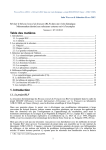
For a more complete understanding of the invention, its
objects and advantages, reference may be had to the folloW
ing speci?cation and draWings and to the pseudocode listing
in the Appendix.
prompts in response to keyed-in or voice commands, as Will
be described in detail beloW.
10
sWitched telephone netWork. HoWever, the telephone 10
may be connected to the public sWitched telephone netWork
BRIEF DESCRIPTION OF THE DRAWINGS
directly or through Well-knoWn means other than the PBX
42.
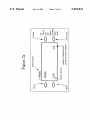
FIG. 1 is an elevation vieW of a multimodal voice dialing
digital telephone according to a preferred embodiment;
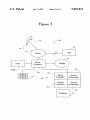
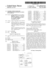
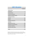
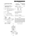
Referring to FIG. 3, an overall system block diagram of
the components of the telephone 10 shoWn generally at 40.
The telephone 10 communicates With a private branch
eXchange (PBX) 42, Which in turn is connected to a public
15
FIGS. 2a and 2b (collectively referred to as FIG. 2) are
vieWs of alternative displays that may be used in the
Still referring to FIG. 3, the telephone also has a phone
processor 46 that handles basic phone operation such as
telephone of FIG. 1;
handling keypad input and Writing to the display 24. The
FIG. 3 is a block diagram of the components comprising
the telephone shoWn in FIG. 1;
FIG. 4 is a diagram shoWing the data stored in the
telephone database shoWn in FIG. 3;
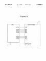
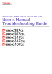
FIG. 5 is a schematic pin-out diagram of the processor and
the speech card of the telephone of FIG. 1;
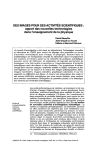
FIG. 6 is a data How diagram shoWing the major func
tional components of the multimodal telephone system and
hoW data ?oWs among those systems;
speech module 52 is connected to the phone processor 46 to
add voice command capability to the telephone that func
tions in parallel With the LCD 24 in accordance With the
present invention. The speech module includes a speech
processor 53 that handles speech recognition, synthesis and
operates the dialog manager. The speech processor 53
25
The speech module 52 also includes a speech recogniZer
56, a speech synthesiZer 58, and a dialog manager 54. The
FIG. 7 is an overvieW of a state machine diagram depict
ing hoW the respective state machines of the phone proces
sor and the dialog manager are integrated;
FIGS. 8 and 9 collectively represent the state machine of
the dialog manager, shoWing What control function states are
possible in the preferred embodiment and hoW those states
are hierarchically arranged;
FIG. 10 is a phoneme similarity time series for the Word
accesses database 44 to retrieve stored data used in inter
preting the user’s commands. Phone processor 46 is con
nected to the speech processor 53.
speech module can be implemented as a separate card that
connects to the phone processor 46. The speech recogniZer
56 is responsive to voice commands entered through the
voice data entry device in accordance With the speech
35
recognition logic described beloW. The speech synthesiZer
56 provides audible prompts to the user through the micro
phone 16 in response to commands from the processor and
“hill” spoken by tWo speakers;
the dialog manager 54.
FIG. 11 is a series of graphs shoWing the output of the
region picking procedure Whereby similarity values are
converted into high similarity regions;
As shoWn in FIG. 4, The database 44 is preferably
constructed using a combination of read-only memory for
static prompts and read/Write nonvolatile memory for
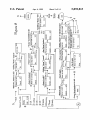
FIG. 12 is a block diagram of the presently preferred Word
recognizer system;
dynamic prompts. More speci?cally, the read-only memory
FIG. 13 is a block diagram illustrating the target congru
ence Word prototype training procedure.
stores the speaker-independent commands. These are key
Words that cause the system to perform various system
45
functions identi?ed in Table 1 beloW. The user may retrain
DETAILED DESCRIPTION
these speaker-independent commands, replacing them With
Amultimodal voice dialing digital telephone according to
speaker-dependent commands that are then stored in the
read/Write memory. When a speaker retrains a command, the
a preferred embodiment of the present invention is shoWn
generally at 10. The telephone 10 is of the type manufac
speaker-dependent command overrides the speaker
tured by Matsushita Electric Industrial Company, Ltd. and
independent one. Speaker-dependent commands are entered
includes a handset 12 With a speaker 14 and a mouthpiece
microphone 16. The telephone also includes a keypad 18 for
entering alphanumeric data into the phone, as is Well knoWn
in the telephonic art. AtWo Way transceiver 20 located beloW
the key pad alloWs hands free tWo Way communication
betWeen a telephone user (not shoWn) and the telephone, as
is also Well knoWn in the telephonic art.
The telephone 10 also includes a liquid crystal display
(LCD) 24 that displays commands entered through a plu
rality of buttons or keys 26. The siZe of the display Will
through the microphone 16 of the telephone handset. The
read-only memory also stores the phone models that are
55
also stores static prompts. These are prompts that are sup
plied to the user via the LCD display 24. Dynamic prompts,
representing prompts that can be altered by the user are
stored in read/Write memory. Also stored in read-Write
memory are the speaker-dependent names and associated
telephone numbers that serve as the user’s personal phone
book. Speaker-dependent names are entered using micro
depend upon the styling and functionality desired. The
presently preferred embodiment uses a tWo line LCD, shoWn
in greater detail in FIG. 2a. The LCD shoWn at 24 in FIG.
2a is a tWo line LCD capable of displaying a total of 16
characters on each line. An alternate seven line, 16 charac
ters per line LCD is shoWn at 24 in FIG. 2b. The LCD
used by the speech recogniZer 56. The read-only memory
phone 16; the associated telephone numbers are entered
using keypad 18.
65
The database preferably has enough memory to store at
least 100 names and telephone numbers, along With the other
information illustrated in FIG. 4.
5,892,813
5
6
TABLE 1
manager through its state machine 92 maintains a record of
the current interaction between the user and the telephone,
including how the user arrived at that point in the dialog,
where applicable. For example, if the user has entered the
command “call” followed by the name “Carl,” the state
machine 92 stores the fact that the user is attempting to place
a call, as opposed to storing a telephone number for the party
KEYWORDS
System
Add
Cancel
Delete
Call
Lookup
Verify
Reset
List
Restore
Program
Complete
Edit
All names
Yes
Adapt
No
Go back
“Carl.” The dialog context is used by the speech recognizer
to help determine which is the most likely candidate for
selection as the recognized word. Thus, in the preceding
example, the speech recognizer would not confuse the word
“Carl” for the word “call” because the word “Carl” followed
the word “call,” signifying that the word “Carl” is not a
Next one
Restart
command but a name. The dialog context is also used to
identify which commands are allowed at any given level in
15
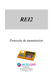
Aschematic pin out diagram showing the interconnection
of the processor 46 with the speech module 52 is shown in
FIG. 5. Signal functions of the processor 46 and the speech
module 52 are given below in Table 2.
the possible commands at this point in the dialog.
TABLE 2
SIGNAL
IN
OUT
FUNCTION
ALUN
X
X
Speech card unit sign
ALBO
ALB1
ALBZ
ALB3
X
X
X
X
X
X
X
X
ASTR
AACK
X
Interface control signal
Speech card ACK
AARQ
X
Speech card access
X
Data
Data
Data
Data
INT
ACT
NOTE
L
L:Installed
DO
D1
D2
D3
25
H
H
L
L
H
L
L:On
access
The digital voice telephone of the present invention may
be operated through use of the keys 26 through voice
commands processed by the speech module 52, or through
The connection between dialog manager 54 and APU 46
ensures that these two processors operate in synchronism.
Thus, if a user selects a soft key 26 associated with a given
prompt on the display 24, that selection is sent to the dialog
manager 54, where the information is used to cycle state
machine 92 to the proper dialog context. Alternatively, if the
user enters a verbal command that is recognized by speech
recognizer 56, a dialog manager sends the command to APU
46, where it is carried out just as if the user had entered it
through the soft key 26 or keypad 18. The dialog manager
is capable of sophisticated processing of a user’s input
signal
request signal
the dialog. By virtue of the bidirectional connection between
the dialog manager 54 and the APU 46, the allowed com
mands at any stage in the dialog are also furnished to the
display 24. This gives the user a visual indication of what are
35
a combination of both the keys and voice commands.
Therefore, if, for some reason the speech module 52 is
disabled, the telephone 10 may function as a conventional
before transmitting control commands to the APU. For
example, the dialog manager upon receipt of a command
“call Carl” would look the name “Carl” up in database 44
and obtain the telephone number stored for that party. The
dialog manager would then send commands to APU 46 that
are interpreted by APU 46 as numeric digits entered via
keypad 18. In this way, the telephone performs a voice
dialing function.
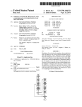
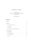
FIG. 7 shows in greater detail how the state machine 90
and state machine 92 integrate with one another. In FIG. 7
the states of state machine 90 are depicted using circles and
the top level states of state machine 92 are depicted using
digital telephone without voice command capability.
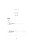
Refer now to FIG. 6. FIG. 6 illustrates the major func
tional components of the multimodal telephone of the inven
tion. The phone processor or APU 46 supports the display 24
and also the keypad 18. The speech module 52 comprises the
speech synthesizer 58. If the speech module 52 is not
rectangles. For example, when the user ?rst lifts the handset
of a telephone to use it, the state machine of APU 46 (state
machine 90) is in the ready call state 200. The user will hear
a dial tone through the speaker of the handset. From this
connected to the APU 46, the APU 46 will nevertheless
state the user may use the keypad buttons 18 to dial a number
function as a standard touchtone telephone. The APU
includes its own processor and associated memory that
de?ne a state machine 90. Speci?cally, state machine 90
read call state 200 the user may activate the redial button on
the telephone to enter redial state 204. In this state the APU
dialog manager 54, including the speech recognizer 56 and
45
and enter the conversation state 202. Alternatively, from the
describes the various telephone operating states that the user
automatically dials the last dialed number, whereupon the
may place the telephone system in. These states include, for
example, placing a call on hold, forwarding an incoming call
conversation state 202 is entered. Similarly, the user can
press a speed dial button that has been previously pro
grammed with a frequently used phone number. This causes
to another number, transferring a call, and so forth. These
states are typically those provided by conventional digital
55
the state machine 90 to enter state 206. In this state the APU
telephones for use with PBX systems. The keypad 18 serves
dials the stored number and then enters the conversation
as the user input to APU 46 and the display 24 serves as the
user output.
state 202. While in the conversation state the user may press
the hold button, causing the state machine to index to the
The telephone of the present invention differs signi?
cantly from conventional digital telephones by virtue of the
dialog manager 54 and its associated speech recognizer and
speech synthesizer modules. The dialog manager is coupled
to the APU to support bidirectional communication with the
APU. The speech recognizer 56 serves as the user input and
the speech synthesizer 58 serves as the user output. The
dialog manager de?nes its own state machine 92. This state
machine maintains the dialog context. That is, the dialog
hold state 208. While in the conversation state the user may
also transfer a call by pressing the transfer button on the
telephone, causing state machine 90 to index to the transfer
state 210. Similarly, while in the conversation state, the user
can press the conference call button, causing the state
65
machine to index to the conference call state 212. The
transfer and conference call buttons place the call on hold
while allowing the user to establish contact with another
party.
5,892,813
7
8
The presently preferred telephone unit includes as one of
its function key buttons, a voice key button that, When
activated from certain states, Will invoke the services of the
dialog manager and its associated state machine 92. In FIG.
7 the voice key state 214 may be entered from some (but not
all) of the states of state machine 90. As illustrated, the voice
key state 214 may be entered from the ready call state 200,
from the hold state 208, from the transfer state 210 and from
the conference call state 212. Entering this state, in effect,
HoWever, because state machine 92 adds functionality to the
telephone system that is not found in the APU-driven system
alone, state machines 90 and 92 do not entirely overlap one
another.
Referring to FIGS. 8 and 9, the ready call state 220 serves
as the starting point from Which the basic top level func
tional states 222—236 can be selected. See pseudocode in
Appendix for an example of hoW this top level state may be
activates the dialog manager. The dialog manager begins in
the ready call state 220, Which is the primary access point for
the remaining states of state machine 92 illustrated at
222—236. Each of the states of state machine 92 are
described in detail in connection With FIGS. 8 and 9.
From a functional standpoint, the ready call state 200 of
state machine 90 and the ready call state 220 of state
10
15
programmed. Each of these functional states leads to a
plurality of additional states that the user Will enter and exit
While conducting a dialog With the dialog manager. The
timeout timer 240 (FIG. 7) is set at every state in the dialog
unless otherWise speci?ed. In the state diagrams of FIGS. 8
and 9, the designation “K” stands for “keyWord.” In the
preferred embodiment, the commands displayed on the LCD
are listed by decreasing likelihood order. The preferred
embodiment uses soft keys to effect scroll up and scroll
doWn functions, alloWing the user to vieW more options than
can be displayed at any one time on the liquid crystal display
machine 92 coincide. Stated differently, When the voice key
state is entered, the functional states 222—236 of state
machine 92 are, in effect, added to the functionality of the
telephone unit as de?ned by state machine 90. Thus, for
example, from the call state 222, the dialog manager Will
screen. By using a list display technique, the system can be
easily upgraded to add additional commands or functions,
obtain the name to lookup by performing speech
simply by adding those additional keyWords to the displayed
list. This approach avoids the necessity of reprogramming
recognition, look up the name in the database and then dial
the entire state machine system When neW functions are
the number by sending the appropriate dialing commands to
the APU. Having done this, the system Would then be in the
added.
25
The present invention employs a unique compact speech
representation based on regions of high phoneme similarity
conversation state 202, just as if the user had manually
dialed the number from the ready call state 200. Although
values. As shoWn in FIG. 10, there is an overall consistency
some of the functional states 222—236 of state machine 92
Will cause state changes to occur in state machine 90 (as the
in the shape of the phoneme similarity time series for a given
Word. In FIG. 10 phoneme similarity time series for the Word
voice dialing function does), not all of the them do.
“hill” spoken by tWo speakers are compared. Although the
HoWever, state machine 92 serves the additional function of
precise Wave shapes differ betWeen the tWo speakers, the
maintaining a record of the current dialog context; that is,
the context in Which the user’s input is to be interpreted. The
phoneme similarity data nevertheless exhibit regions of
similarity betWeen the speakers. Similar behavior is
observed in the phoneme plausibility time series that has
dialog manager maintains a data structure that de?nes the
possible states of state machine 92 as Well as hoW those 35 been described by Gong and Haton in “Plausibility Func
states are hierarchically related. This data structure thus
tions in Continuous Speech Recognition: The VINICS
serves to de?ne What commands are possible from any given
System,” Speech Communication, Vol. 13, October 1993,
state Within the state machine. The dialog manager main
pp. 187—196.
tains a pointer to the currently active state (that is, the state
Conventional speech recognition systems match each
that the user most recently selected). Knowing the currently
input utterance to reference templates, such as templates
composed on phoneme similarity vectors, as in the model
speech method (MSM) of Hoshimi et al. In these conven
active state, the dialog manager consults the data structure to
determine What are the possible operations that can be
performed from the active state and What prompts are
appropriate for the active state. The dialog manager com
municates the dialog context to the phone processor that in
tional systems the reference speech representation is frame
45
turn displays What commands are possible upon the liquid
crystal display. In this Way, the user Will alWays knoW What
commands are possible by looking at the LCD display.
computationally costly and makes this approach unsuitable
for larger vocabularies, especially When using small hard
The presently preferred implementation Will automati
Ware.
cally revert from the ready call state 220 to the ready call
state 200 after a predetermined time has elapsed Without any
action being taken. This is illustrated diagrammatically by
the timer 240 in FIG. 7. The timeout duration Will depend on
the particular dialog context. For example, the system Will
Wait for a longer time (eg 2 minutes) in the top level states,
55
such as the ready call state 220. The system Will Wait a
shorter time (eg 2 seconds) When the system is in a loWer
state that provides a default action to automatically take
place if the user does not respond.
The state machine 92 of the presently preferred embodi
betWeen the dialog manager and the APU, these tWo state
machines Work in full synchronism With one another.
The present system uses a multistage Word recogniZer that
is applied prior to a frame-by-frame alignment, in order to
reduce the search space and to achieve real time perfor
mance improvements. The number of stages in the
recogniZer, as Well as the computational complexity of each
stage and the number of Word candidates preserved at each
stage, can be adjusted to achieve desired goals of speed,
memory siZe and recognition accuracy for a particular
application. The Word recogniZer uses an initial representa
tion of speech as a sequence of multiple phoneme similarity
values. HoWever, the Word recogniZer further re?nes this
speech representation to preserve only the interesting
regions of high phoneme similarity. Referring to FIG. 11, the
interesting regions of high phoneme similarity value are
represented as high similarity regions. By representing the
ment is illustrated in FIGS. 8 and 9. As indicated above, state
machine 92 is implemented by the dialog manager 54.
Essentially, dialog manager 54 augments the states available
through the APU 46 (state machine 90) With additional states
(state machine 92). By virtue of the bidirectional link
based and requires a high data rate, typically 8 to 12
parameters every 10 to 20 milliseconds. The frame-by-frame
alignment that is required With these conventional systems is
65
speech as features at a loWer data rate in the initial stages of
recognition, the complexity of the matching procedure is
greatly reduced.
5,892,813
10
The multistage Word recognizer also employs a unique
scoring procedure for propagating and combining the scores
HS regions over a prede?ned number of time intervals. The
presently preferred embodiment divides Words into three
equal time intervals in Which each phoneme interval is
described by (1) the mean of the number of HS regions
occurring in that interval and (2) a Weight that is inversely
proportional to the square of the variance, Which indicates
obtained at each stage of the Word recogniZer in order to
produce a ?nal Word decision. By combining the quasi
independent sources of information produced at each stage,
a signi?cant gain in accuracy is obtained.
The system’s architecture features three distinct compo
nents that are applied in sequence on the incoming speech to
compute the best Word candidate.
Referring to FIG. 12, an overvieW of the presently pre
ferred system Will be presented. The ?rst component of the
present system is a phoneme similarity front end 110 that
converts speech signals into phoneme similarity time series.
Speech is digitiZed at 8 kilohertZ and processed by 10th
order linear predictive coding (LPC) analysis to produce 10
hoW reliable the region count is. Speci?cally for a score
normaliZed betWeen 0 and 100, the Weight Would be 100/
(variance2+2). These parameters are easily estimated from
10
each Word requires exactly 330 parameters, Which corre
sponds to tWo statistics, each over three intervals each
comprising 55 phoneme units (2 statistics><3 intervals><55
phoneme units).
15
cepstral coef?cients every 100th of a second. Each block of
The region count prototype is constructed as folloWs. A
?rst utterance of a training Word or phrase is represented as
20
phoneme similarity values each centisecond (each 100th of
a second). As illustrated in FIG. 12, the phoneme similarity
intervals, With each time interval being represented by data
corresponding to the 55 phonemes. Thus the presently
front end Works in conjunction With a phone model database
preferred implementation represents each utterance as a
112 that supplies the phoneme reference templates. The
output of the phoneme similarity front end may be stored in
3x55 vector. In representing the utterance as a 3x55 vector,
each vector element in a given interval stores the number of
a suitable memory for conveying the set of phoneme simi
larity time series so generated to the Word recogniZer stages.
similarity regions that are detected for each given phoneme.
30
phoneme similarity values are discarded, as illustrated in
FIG. 11. In the preferred embodiment regions are charac
An inductive or iterative process is then performed for
each of the successive utterances of the training Word or
phrase. Speci?cally, each successive utterance is represented
35 as a vector like that of the ?rst utterance. The tWo vectors are
then combined to generate the vector sum and the vector
sum of the squares. In addition, a scalar count value is
teriZed by 4 parameters: phoneme symbol, height at the peak
maintained to keep track of the current number of utterances
that have been combined.
location and time locations of the left and right frames. Over
our data corpus, an average of 60 regions per second of
speech is observed. In FIG. 12 the high similarity region
extraction module 116 performs the peak driven procedure.
The output of the HS region extraction module is supplied
to tWo different Word recogniZer stages that operate using
40
The process proceeds inductively or iteratively in this
fashion, each neW utterance being combined With the pre
vious ones such that the sum and sum of squares vectors
ultimately represent the accumulated data from all of the
utterances.
different recogniZer techniques to provide a short list of
Word candidates for the ?ne match ?nal recogniZer stage
126.
The ?rst of the tWo stages of Word recogniZer 114 is the
Region Count stage or RC stage 118. This stage extracts a
short list of Word candidates that are then supplied to the
Thus if three occurrences of the phoneme “ah” occur in the
?rst interval, the number 3 is stored in the vector element
corresponding t the “ah” phoneme.
driven procedure extracts High Similarity Regions (HS
Regions). In this process, loW peaks and local peaks of
time-dependent phoneme similarity data. In the presently
preferred embodiment each utterance is divided into N time
intervals. Presently each utterance is divided into three time
shifted by one frame at a time to produce a vector of
The Word recogniZer stages, depicted in FIG. 12 generally
at 114, comprise the second major component of the system.
A peak driven procedure is ?rst applied on the phoneme
similarity time series supplied by front end 110. The peak
Region count modeling Was found to be very effective due
to its fast alignment time (0.33 milliseconds per test Word on
a Sparc10 Workstation) and its high top 10% accuracy.
10 successive frames of cepstral coef?cients is compared to
55 phoneme reference templates (a subset of the TIMIT
phoneme units) to compute a vector of multiple phoneme
similarity values. The block of analysis frames is then
training data. In the currently preferred implementation,
Once all training utterances have been processed in this
fashion the vector mean and vector variance are calculated.
The mean vector is calculated as the sum vector divided by
the number of utterances used in the training set. The vector
variance is the mean of the squares minus the square of the
50 means. The mean and variance vectors are then stored as the
next stage of the Word recogniZer 114, the Target Congru
region count prototype for the given Word or phrase. The
ence stage or TC stage 120. The RC stage 118 has an RC
same procedure is folloWed to similarly produce a mean and
variance vector for each of the remaining Words or phrases
in the lexicon.
When a test utterance is compared With the RC prototype,
the test utterance is converted into the time dependent
phoneme similarity vector, essentially in the same Way as
each of the training utterances Were converted. The Euclid
Word prototype database 122 that supplies compact Word
representations based on the novel compact speech repre
sentation (regions of high phoneme similarity values) of the
55
invention. Similarly, the TC stage 120 also includes a TC
Word prototype database 124 that supplies a different com
pact Word representation, also based on the compact speech
representation of the invention. The TC stage provides a
more selective short list of Word candidates, essentially a
ean distance betWeen the test utterance and the prototype is
60
further re?nement of the list produced by the RC stage 118.
The Word decision stage 126, the ?nal major component
of the present system selects the Word With the largest score
from the short list supplied by TC stage 120.
Region Count Modeling
The RC stage 118 of Word recogniZer 114 represents each
reference Word With statistical information on the number of
computed by subtracting the test utterance RC data vector
from the prototype mean vector and this difference is then
squared. The Euclidean distance is then multiplied by a
Weighting factor, preferably the reciprocal of the prototype
65
variance. The Weighted Euclidean distance, so calculated, is
then converted into a scalar number by adding each of the
vector component elements. In a similar fashion the Weight
ing factor (reciprocal of the variance) is converted into a