1
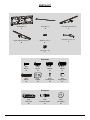
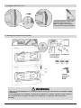
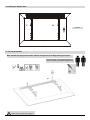
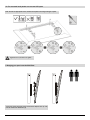
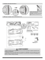
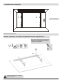
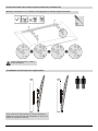
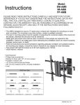
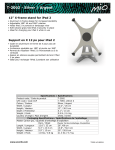
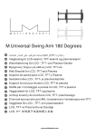
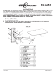
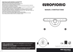
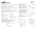
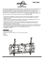
EM-T2000
INSTRUCTIONS
PLEASE READ THESE INSTRUCTIONS CAREFULLY AND KEEP FOR FUTURE REFERENCE! IF
YOU DO NOT UNDERSTAND THE INSTRUCTIONS, OR DO NOT FEEL THAT YOU CAN
FOLLOW THEM SAFELY, CONTACT A QUALIFIED CONTRACTOR. THE WARRANTY WILL BE
HONOURED IF ACCOMPANIED BY AN ORIGINAL SALES RECEIPT, AND ONLY IF THE
INSTRUCTIONS HAVE BEEN FOLLOWED EXACTLY. To acquire missing parts please visit
http://www.everik.com/en-CA/Parts-Request.html or call 1-866-604-6966.
• These mounts are designed to mount a panel onto a vertical wall. Hardware for mounting to a
wood stud is included. For mounting to any other surface, it is recommended you contact a
qualified contractor.
• The wall or mounting surface must be capable of supporting the combined weight of the mount
and the flat panel, otherwise the structure must be reinforced.
• Safety gear and proper tools must be used. A minimum of two people are required for this
installation. Failure to use safety gear and/or attempting this installation alone can result in
property damage, serious injury, or death.
• Follow all instructions and recommendations regarding adequate ventilation and suitable locations
for mounting your flat panel. Consult the owner’s manual of your flat panel for more information.
• This product will hold flat panels up to 70” and weighing up to 88 lbs.
• VESA 600mm x 400mm
Tools Required
• Phillips head screwdriver
• M6 socket and wrench
• Electric drill and 10mm masonry bit for concrete wall installation
• Pencil
• Hammer
• Stud finder
1
EM-T1000..LU.092013.IM
PARTS LIST
Wall Mount (1)
A
Safety Bar (1)
B
Left Adapter Bracket (2)
C
Right Adapter Bracket (2)
D
Bubble Level (1)
E
Decorative Covers (2)
F
ST2.9 x 6.5 (4)
G
Package M
M-A
M5x14
x4
M-B
M6x14
x4
M-C
M8x20
x4
M-D
M6x30
x4
M-E
M8x30
x4
M-F
Washer
x4
M-G
Small spacer
x8
M-H
Large spacer
x4
Package W
W-A
ST6.3x55
x6
2
W-B
Concrete anchor
x6
W-C
D6 washer
x6
EM-T1000..LU.092013.IM
1. Installing the Decorative Covers
Attach the decorative covers to the
wall plate using screws (G) x4.
Note: The gap on the decorative
covers should be facing downwards.
2a. Mounting the wall plate into wooden studs
* Make sure that the mounting screws are anchored into the center of the studs. The use of a stud finder is highly
recommended.
* It is recommended to use a drill driver to tighten bolts. Tighten bolts so that the wall plate is firmly attached to
the wall, but DO NOT over-tighten. The bolts can be damaged by over-tightening which will strip their
threading.
3
EM-T1000..LU.092013.IM
2b. Mounting the wall plate into concrete
* When installing wall mounts on cinder block, verify the actual concrete thickness is at least 1-3/8” (35mm) for
using the concrete anchors. Do not drill into mortar joints! Be sure to mount in a solid part of the block,
generally 1” (25mm) minimum from the side of the block. It is suggested to use an electric drill on slow setting to
drill the hole instead of a hammer drill to avoid breaking out the back of the hole when entering a void or cavity.
* It is recommended to use a drill driver to tighten bolts. Tighten bolts so that the wall plate is firmly attached to
the wall, but DO NOT over-tighten. The bolts can be damaged by over-tightening which will strip their
threading.
4
EM-T1000..LU.092013.IM
3. Installing the Adaptor Arms
C
D
Top of TV
3a. For flat back panels
Note: Choose the appropriate screws, washers and spacers according to the type of panel.
Using two people, lay your flat panel down on a
clean, soft surface and install the Adaptor Arms
Tighten all screws, but do not over tighten.
5
EM-T1000..LU.092013.IM
3b. For recessed back panels or to access A/V inputs.
Note: Choose the appropriate screws, washers and spacers according to the type of panel.
Tighten all screws, but do not over tighten.
4. Hanging your panel onto the Wall Plate
*Using two people, lift panel slowly and hook the Adaptor Arms (C & D)
onto the head of the Wall Plate (A)
6
EM-T1000..LU.092013.IM
4. Hanging your panel onto the Wall Plate
Insert the safety bar
*Use a padlock to prevent theft. (The padlock is not included)
5. Final Adjustments
Push or pull from the top or bottom of the screen to obtain the desired angle.
7
EM-T1000..LU.092013.IM
EM-T2000
INSTRUCTIONS
VEUILLEZ LIRE CES INSTRUCTIONS ATTENTIVEMENT ET LES GARDER POUR Y RÉFÉRER AU
BESOIN. SI VOUS NE COMPRENEZ PAS LES INSTRUCTIONS OU SI VOUS NE CROYEZ PAS ÊTRE EN
MESURE DE LES SUIVRE EN TOUTE SÉCURITÉ, VEUILLEZ COMMUNIQUER AVEC UN TECHNICIEN
QUALIFIÉ. LA GARANTIE NE SERA HONORÉE QU'EN LA PRÉSENCE DU COUPON DE CAISSE
ORIGINAL ET UNIQUEMENT SI LES INSTRUCTIONS ONT ÉTÉ SUIVIES À LA LETTRE. Pour obtenir des
pièces manquantes, visitez www.everik.com/parts.html ou téléphonez au 1 866 604-6966.
• L'IM-ALB3 est conçu pour fixer un moniteur sur un mur vertical. Le matériel servant au montage sur mon•
•
•
•
•
tant de bois est inclus. Pour le montage sur toute autre surface, veuillez communiquer avec un
technicien qualifié.
Le mur ou la surface de montage doit être capable de supporter le poids combiné du support et du
moniteur, sinon la structure doit être renforcée.
Un équipement de sécurité et des outils appropriés doivent être utilisés. Un minimum de deux personnes
sont nécessaires pour cette installation. Ne pas utiliser d'équipement de sécurité et/ou tenter cette
installation seul peut entraîner des dommages matériels, des blessures graves ou la mort.
Suivez toutes les instructions et recommandations concernant la ventilation adéquate et le choix d'un
emplacement approprié pour le montage de votre moniteur. Consultez le manuel de l'utilisateur de votre
moniteur pour plus d'informations.
Ce produit peut supporter des moniteurs jusqu'à 70 po, pesant jusqu'à 88 lb.
VESA 600 mm x 400 mm
Outils nécessaires
• Tournevis à tête cruciforme
• Clé et douille M6
• Perceuse électrique avec foret de maçonnerie 10 mm pour installation sur un
mur de béton
• Marqueur ou crayon
• Marteau
• Détecteur de montant
8
EM-T1000..LU.092013.IM
LISTE DES PIÈCES
Plaque murale (1)
A
Barre de sécurité (1)
B
Bras adaptateur gauche (2)
C
Bras adaptateur droit (2)
D
Niveau à bulle (1)
E
Plaque décorative (2)
F
ST2.9 x 6.5 (4)
G
Package M
M-A
M5x14
x4
M-B
M6x14
x4
M-C
M8x20
x4
M-D
M6x30
x4
M-E
M-F
M-G
M-H
M8x30
x4
Rondelle
x4
Cale (petit)
x8
Cale (grand)
x4
Package W
W-A
ST6.3x55
x6
9
W-B
Cheville pour béton
x6
W-C
Rondelle D6
x6
EM-T1000..LU.092013.IM
1. Installation des plaques décoratives
Fixez les caches décoratifs à la plaque
murale avec les vis (G) x4.
Remarque : l'ouverture sur les caches
décoratifs doit être orientée vers le
bas.
2a. Montage de la plaque murale sur montants en bois
Trouvez et marquez
l'emplacement exact
des trous de montage
Percez des rous
Vissez le sup-port
mural au mur
AVERTISSEMENT
* Assurez-vous que les vis de montage sont bien ancrées au centre des montants. L'utilisation d'un détecteur de
montants est recommandée.
* L'utilisation d'une perceuse-visseuse pour visser les boulons est recommandée. Serrez les boulons de sorte que
la plaque murale soit fermement fixée au mur, mais NE les serrez PAS trop fort. Cela pourrait endommager les
boulons et en abîmer le filetage. threading.
10
EM-T1000..LU.092013.IM
2b. Montage de la plaque murale sur mur de béton
Marquez
l'emplacement exact
des trous de montage
Percez des rous
Vissez le sup-port
mural au mur
AVERTISSEMENT
* Si vous installez le support mural sur un bloc de béton, assurez-vous de disposer d'une épaisseur de béton d'au
moins 1 3/8" (35 mm) pour les chevilles. Ne percez jamais dans un joint de mortier! Assurez-vous d'effectuer le
montage dans une partie pleine du bloc de béton, soit environ à 1 po (25 mm) du côté du bloc. Utilisez une perceuse électrique réglée à vitesse lente, plutôt qu’un marteau perforateur, pour éviter de briser le fond du trou
lorsque vous entrez un vide ou une cavité.
* L'utilisation d'une perceuse-visseuse pour visser les boulons est recommandée. Serrez les boulons de sorte que
la plaque murale soit fermement fixée au mur, mais NE les serrez PAS trop fort. Cela pourrait endommager les
boulons et en abîmer le filetage.
11
EM-T1000..LU.092013.IM
3. Installation des bras adaptateurs
C
D
Haut du téléviseur
3a. Pour les écrans à dos
Remarque : Choisissez les vis, rondelles et cales appropriés en fonction du type d'écran plat.
Avec l'aide d'une autre personne, placez votre
écran plat sur une surface propre et plane, et
installez la bras adaptateurs.
Assurez-vous de bien serrer les vis, mais ne
les serrez pas trop fort.
12
EM-T1000..LU.092013.IM
3b. Pour les écrans à dos concave ou pour accéder aux connexions A/V
Remarque : Choisissez les vis, rondelles et cales appropriés en fonction du type d'écran plat.
Assurez-vous de bien serrer les vis, mais ne
les serrez pas trop fort.
4. Installation de l'écran plat sur le support mural
Mur
Mur
*Avec l'aide d'une autre personne, soulevez lentement le
téléviseur et accrochez les bras d'adaptation (C & D) sur le
dessus de la plaque murale (A).
13
EM-T1000..LU.092013.IM
4. Installation de l'écran plat sur le support mural
Le pli est orienté
vers l'intérieur
Insérez la tige de sécurité (B)
*Utilisez un cadenas pour empêcher le vol (cadenas non fourni).
5: Derniers ajustements
Tirez ou poussez en haut ou en bas de l'écran pour obtenir l'angle désiré.
14
EM-T1000..LU.092013.IM