1
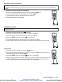
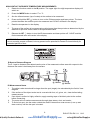
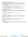
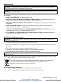
RESISTANCE MEASUREMENTS WARNING: To avoid electric shock, disconnect power to the unit under test and discharge all capacitors before taking any resistance measurements. Remove the batteries and unplug the line cords. 1. Rotate the function switch to the Ω position. 2. Insert the black test lead banana plug into the negative COM jack. Insert the red test lead banana plug into the positive jack. 3. Touch the test probe tips across the device under test. 4. Read the resistance in the display. CONTINUITY CHECK WARNING: To avoid electric shock, never measure continuity on circuits or wires that have a voltage potential. 1. Rotate the function switch to the position. 2. Insert the black lead banana plug into the negative COM jack. Insert the red test lead banana plug into the positive jack. 3. Press the MODE button to indicate“ "on the display 4. Touch the test probe tips to the circuit or wire you wish to check. 5. If the resistance is less than the continuity threshold, the audible signal will sound. DIODE TEST 1. Rotate the function switch to the green position. 2. Insert the black test lead banana plug into the negative COM jack and the red test lead banana plug into the positive jack. 3. Press the MODE button to indicate “ “and “V” on the display. 4. Touch the test probes to the diode under test. Forward voltage will typically indicate 0.400 to 0.700V. Reverse voltage will indicate “OL”. Shorted devices will indicate near 0V and an open device will indicate “OL” in both polarities. nd Quality Products Online at: 7 www. GlobalTestSupply.com EX210T-EU-EN V1.1 8/12 [email protected]