1
CL2XY16-DTP1C5V
CC-Link/LT Remote I/O Module
User’s Manual
(Hardware)
Thank you very much for purchasing this product.
Please read this manual thoroughly before starting to use the
product and handle the product properly.
MODEL CL2XY16-DTP1C5V-U
MODEL
13JP27
CODE
IB(NA)-0800260-C(1406)MEE
© 2003 MITSUBISHI ELECTRIC CORPORATION
SAFETY PRECAUTIONS
(Read these precautions before using this product.)
Before using this product, please read this manual and the relevant manuals
carefully and pay full attention to safety to handle the product correctly.
In this manual, the safety precautions are classified into two levels:
"
WARNING" and "
CAUTION".
WARNING
Indicates that incorrect handling may cause
hazardous conditions, resulting in death or severe
injury.
CAUTION
Indicates that incorrect handling may cause
hazardous conditions, resulting in minor or moderate
injury or property damage.
Under some circumstances, failure to observe the precautions given under
"
CAUTION" may lead to serious consequences.
Observe the precautions of both levels because they are important for personal
and system safety.
Make sure that the end users read this manual and then keep the manual in a safe
place for future reference.
[DESIGN PRECAUTIONS]
WARNING
● Refer to Chapter 3 of this manual for the operation status of the module in
case a communication error occurs in the data link.
● Output could be switched on or off when a problem occurs in the remote I/O
modules. So build an external monitoring circuit that will monitor any output
signals that could cause a serious accident.
CAUTION
● Do not have control cables and communication cables bundled with or
placed near by the main circuit and/or power cables. Wire those cables at
least 100mm(3.94 inch) away from the main circuit and/or power cables. It
may cause malfunction due to noise interference.
A-1
[INSTALLATION PRECAUTIONS]
CAUTION
● Use the module in an environment that meets the general specifications
contained in this manual. Using this module in an environment outside the
range of the general specifications could result in electric shock, fire,
erroneous operation, and damage to or deterioration of the product.
● Do not directly touch the module's conductive parts.
Doing so could cause malfunction or trouble in the module.
● Securely fix the module in place using the DIN rail. If the module is not
securely fixed, it may fall off or cause malfunction.
[WIRING PRECAUTIONS]
WARNING
● Perform installation and wiring after disconnecting the power supply at all
phases externally. If the power is not disconnected at all phases an electric
shock or product damage may result.
CAUTION
● Wire the module correctly upon verifying the product's rated voltage and the
connector pin arrangement. Connecting to a power supply different from
rating or miss-wiring may cause fire and/or product failure.
● Make sure foreign objects do not get inside the module, such as dirt and wire
chips. It may cause fire, product failure or malfunction.
[STARTING AND MAINTENANCE PRECAUTIONS]
WARNING
● Do not touch the connector pins when the power is on. It may cause an
electric shock or malfunction.
● Before cleaning the module, be sure to shut off all the phases of the power
supply externally.
Failure to do so may cause failure or malfunction of the modules.
A-2
[STARTING AND MAINTENANCE PRECAUTIONS]
CAUTION
● Do not disassemble or modify the module. Doing so may cause failure,
malfunction, injury, or fire.
● The module case is made of resin; do not drop it or subject it to strong shock.
A module damage may result.
● Make sure to switch all phases of the external power supply off before
installing or removing the module to/from the panel. Failure to do so may
cause failure or malfunction of the modules.
● Before touching the module, always touch grounded metal, etc. to discharge
static electricity from the human body, etc.
Not doing so can cause the module to fail or malfunction.
[DISPOSAL PRECAUTIONS]
CAUTION
● When disposing of this product, treat it as industrial waste.
A-3
PRÉCAUTIONS DE SÉCURITÉ
(Lire ces précautions avant toute utilisation du produit.)
Avant d'utiliser ce produit, lire attentivement ce manuel ainsi que les manuels
auxquels il renvoie, et toujours considérer la sécurité comme de la plus haute
importance en manipulant le produit correctement.
Dans ce manuel, les précautions de sécurité sont classées en deux niveaux, à
savoir : "AVERTISSEMENT" et "ATTENTION"
AVERTISSEMENT
ATTENTION
Attire l'attention sur le fait qu'une négligence peut
créer une situation de danger avec risque de mort
ou de blessures graves.
Attire l'attention sur le fait qu'une négligence peut
créer une situation de danger avec risque de
blessures légères ou de gravité moyennes ou
risque de dégâts matériels.
Dans certaines circonstances, le non-respect d'une précaution de sécurité
introduite sous le titre "ATTENTION" peut avoir des conséquences graves.
Les précautions de ces deux niveaux doivent être observées dans leur intégralité
car elles ont trait à la sécurité des personnes et aussi du système.
Veiller à ce que les utilisateurs finaux lisent ce manuel qui doit être conservé
soigneusement à portée de main pour s'y référer autant que de besoin.
[Précautions lors de la conception]
AVERTISSEMENT
● Pour l'état opérationnel du module en cas d'erreur de communication dans la
liaison de données, se reporter au Chapitre 3 du présent manuel.
● La sortie pourrait se trouver activée ou désactivée à la survenance d'un
problème dans le module E/S distant. On constituera donc un circuit de
surveillance externe couvrant tous les signaux de sortie qui pourraient être à
l'origine d'un accident grave.
ATTENTION
● Ne pas grouper ni placer à proximité les câbles de commande ou câbles de
communication avec les câbles des circuits principaux et/ou d'alimentation.
Câbler en plaçant ces câbles à une distance d'au moins 100mm (3,94
pouces) des câbles des circuits principaux ou de l'alimentation. Cela pourrait
être à l'origine d'un bruit parasite entraînant des dysfonctionnements.
A-4
[Précautions d'installation]
ATTENTION
● Utiliser le module dans un environnement conforme aux spécifications
générales présentées dans ce manuel. L'utilisation de ce module dans un
environnement autre que celui prévu dans les spécifications générales peut
être à l'origine d'un choc électrique, d'un départ de feu ou d'un
dysfonctionnement, ou peut endommager ou détériorer le produit.
● Éviter tout contact direct avec les parties conductrices du module.
Cela pourrait être à l'origine de dysfonctionnements ou autres problèmes
avec le module.
● Fixer fermement le module en place sur le rail DIN. Si le module n'est pas
fermement fixé, il risque de tomber ou il peut y avoir des dysfonctionnements.
[Pécautions de câblage]
AVERTISSEMENT
● Effectuer l'installation et le câblage après avoir déconnecté l'alimentation
externe sur toutes les phases. Si l'alimentation n'a pas été coupée sur toutes
les phases, il y a risque d'électrocution ou d'endommagement du produit.
ATTENTION
● Câbler le module correctement après vérification de la tension nominale du
produit et de l'affectation des broches de connecteur. Le raccordement d'une
alimentation de tension nominale différente ou une erreur de câblage peuvent
être à l'origine d'un départ de feu et/ou d'une panne du produit.
● Veiller à éviter toute pénétration d'impuretés, copeaux de câblage ou autre
corps étranger dans le module. Cela pourrait être à l'origine d'un départ de
feu, ou du panne ou d'un dysfonctionnement du produit.
[Précautions de démarrage et de maintenance]
AVERTISSEMENT
● Ne pas toucher aux broches de connecteur quand l'appareil est sous tension.
Cela pourrait être à l'origine d'un choc électrique ou d'un dysfonctionnement.
● Avant de nettoyer le module, vérifier sur l'alimentation externe a bien été
coupée sur toutes les phases.
Faute de quoi, il y a risque de panne ou de dysfonctionnement des modules.
A-5
[Précautions de démarrage et de maintenance]
ATTENTION
● Ne pas démonter ni modifier le module. Cela pourrait être à l'origine de
pannes, de dysfonctionnements, de blessures ou d'un départ de feu.
● Ne pas faire tomber ou soumettre le module à des chocs car son boîtier en
plastique est fragile. Il pourrait en résulter un endommagement du module.
● Avant d'installer le module dans le tableau ou de l'en retirer, il est
indispensable de couper l'alimentation externe sur toutes les phases. Faute
de quoi, il y a risque de panne ou de dysfonctionnement des modules.
● Avant de toucher au module, se débarrasser de la charge électrostatique
qu'accumule le corps humain en touchant un objet métallique raccordé à la
terre.
Faute de quoi, il y a risque de panne ou de dysfonctionnement du module.
[Précaution de mise au rebut]
ATTENTION
● Lors de sa mise au rebut, ce produit doit être traité comme un déchet
industriel.
A-6
CONDITIONS OF USE FOR THE PRODUCT
(1) Mitsubishi programmable controller ("the PRODUCT") shall be used in
conditions;
i) where any problem, fault or failure occurring in the PRODUCT, if any,
shall not lead to any major or serious accident; and
ii) where the backup and fail-safe function are systematically or
automatically provided outside of the PRODUCT for the case of any
problem, fault or failure occurring in the PRODUCT.
(2) The PRODUCT has been designed and manufactured for the purpose of
being used in general industries.
MITSUBISHI SHALL HAVE NO RESPONSIBILITY OR LIABILITY
(INCLUDING, BUT NOT LIMITED TO ANY AND ALL RESPONSIBILITY
OR LIABILITY BASED ON CONTRACT, WARRANTY, TORT, PRODUCT
LIABILITY) FOR ANY INJURY OR DEATH TO PERSONS OR LOSS OR
DAMAGE TO PROPERTY CAUSED BY the PRODUCT THAT ARE
OPERATED OR USED IN APPLICATION NOT INTENDED OR
EXCLUDED BY INSTRUCTIONS, PRECAUTIONS, OR WARNING
CONTAINED IN MITSUBISHI'S USER, INSTRUCTION AND/OR SAFETY
MANUALS, TECHNICAL BULLETINS AND GUIDELINES FOR the
PRODUCT.
("Prohibited Application")
Prohibited Applications include, but not limited to, the use of the PRODUCT
in;
• Nuclear Power Plants and any other power plants operated by Power
companies, and/or any other cases in which the public could be
affected if any problem or fault occurs in the PRODUCT.
• Railway companies or Public service purposes, and/or any other cases
in which establishment of a special quality assurance system is
required by the Purchaser or End User.
• Aircraft or Aerospace, Medical applications, Train equipment, transport
equipment such as Elevator and Escalator, Incineration and Fuel
devices, Vehicles, Manned transportation, Equipment for Recreation
and Amusement, and Safety devices, handling of Nuclear or
Hazardous Materials or Chemicals, Mining and Drilling, and/or other
applications where there is a significant risk of injury to the public or
property.
A-7
Notwithstanding the above, restrictions Mitsubishi may in its sole discretion,
authorize use of the PRODUCT in one or more of the Prohibited
Applications, provided that the usage of the PRODUCT is limited only for
the specific applications agreed to by Mitsubishi and provided further that
no special quality assurance or fail-safe, redundant or other safety features
which exceed the general specifications of the PRODUCTs are required.
For details, please contact the Mitsubishi representative in your region.
A-8
REVISIONS
* The manual number is noted at the lower right of the front cover.
Print Date
Aug., 2003
Dec., 2011
*Manual Number
IB(NA)-0800260-A
IB(NA)-0800260-B
Jun., 2014
IB(NA)-0800260-C
Revision
First printing
Addition of descriptions of SAFETY
PRECAUTIONS(Chinese)
Addition of descriptions of cUL
This manual confers no industrial property rights or any rights of any other kind, nor does it
confer any patent licenses. Mitsubishi electric Corporation cannot be held responsible for any
problems involving industrial property rights which may occur as a result of using the contents
noted in this manual.
© 2003 MITSUBISHI ELECTRIC CORPORATION
A-9
CONTENTS
1. OVERVIEW..................................................................................................... 1
2. SPECIFICATIONS .......................................................................................... 1
2.1 General Specifications.............................................................................. 1
2.2 Performance specifications ...................................................................... 3
3. PART NAMES................................................................................................. 5
4. HANDLING PRECAUTIONS .......................................................................... 9
5. WIRING......................................................................................................... 10
5.1 External wiring ........................................................................................ 10
5.2 Connection and wiring of the connector for I/O interface ...................... 12
6. EXTERNAL DIMENSIONS ........................................................................... 13
A-10
1. OVERVIEW
This user's manual explains specifications and names of individual parts
of the CL2XY16-DTP1C5V type CC-Link/LT remote I/O module
(hereinafter abbreviated as remote I/O module).
2. SPECIFICATIONS
2.1 General Specifications
The General specifications for the remote I/O module are shown in the
following table.
Item
Operating
ambient
temperature
Specifications
0 to 55°C
Température
ambiante de
fonctionnement
Storage ambient
temperature
Operating
ambient humidity
Storage
ambient humidity
0 à 55 °C
-25 to 75°C
5 to 95%RH, non-condensing
Constant
Half
acceleration amplitude
5 to 8.4Hz
———
3.5mm
Frequency
Vibration
resistance
Shock
resistance
Operating
atmosphere
Operating altitude
Installation
location
Overvoltage
category *1
Pollution
degree *2
Compliant
Under
with JIS B intermittent
8.4 to
3502
9.8m/s2
———
vibration
150Hz
and IEC
61131-2
5 to 8.4Hz
———
1.75mm
Under
continuous
8.4 to
4.9m/s2
———
vibration
150Hz
Compliant with JIS B 3502 and IEC 61131-2
(147 m/s2, 3 times each in 3 directions X, Y, Z)
No corrosive gases
0 to 2000m
Inside a control panel *3
II or less
2 or less
1
Sweep
count
10 times
each in
X, Y, Z
directions
———
*1
*2
*3
This indicates the section of the power supply to which the equipment is
assumed to be connected between the public electrical power distribution
network and the machinery within premises. Category II applies to
equipment for which electrical power is supplied from fixed facilities.
The surge voltage withstand level for up to the rated voltage of 300 V is 2500
V.
This index indicates the degree to which conductive material is generated in
terms of the environment in which the equipment is used.
Pollution level 2 is when only non-conductive pollution occurs. A temporary
conductivity caused by condensing must be expected occasionally.
It can also be used in an environment other than on the control panel if the
conditions such as usage ambient temperature and humidity are satisfied.
2
2.2 Performance specifications
The performance specifications for the remote I/O module are shown in
the following table.
Type
CL2XY16-DTP1C5V
Item
Input specifications
Number of inputs
Isolation method
Rated load voltage
Rated input current
Max. simultaneous ON
input points
ON voltage/ON current
OFF voltage/OFF
current
Input resistance
Protect function
Response
time setting
Response
OFF
time
→ON
ON→
OFF
TYP.
MAX.
TYP.
MAX.
Input method
Common wiring method
Number of stations
occupied
Voltage
Module Current
power consumption
supply Current on
startup
Noise durability
Output specifications
Number of
8 points
outputs
Photocoupler
Photocoupler isolation
Isolation method
isolation
24V DC (Common
24V DC (Common with the Rated load
with the module
module power supply)
voltage
power supply)
0.1A/point 0.8A/1
Approx. 4mA
Max. load current
common
Max. inrush
100%
0.7A 10ms or lower
current
Leakage current
19V or more/3mA or more
0.1mA or lower
at OFF
0.3V or lower (TYP.)
11V or lower/1.7mA or
Voltage drop at
0.1A, 0.6V or lower
lower
ON
(MAX.) 0.1A
5.6kΩ
Output method
Sink type
Overload protection
Protect function
function ,Overheat
protection function
0.5ms
1.5ms
(High speed (Standard
OFF
response type)
type)
0.5ms or lower
1.5ms
→ON
0.05ms
(Standard
0.1ms
1.5ms type)
0.2ms
ON→ 0.5ms or lower
OFF (Resistive load)
0.5ms
1.5ms
Surge
Positive common
Zener diode
suppression
8 points/1 common
8 points/1 common
Common wiring
(sensor connector 3-wire
(sensor connector 2method
type)
wire type)
In 4-point mode: Occupies 2 stations
In 8 or 16-point mode: Occupies 1 station
24V DC (-15 to +20%) (ripple ratio : within 5%)
8 points
50mA or lower (When 24V DC and all point is on)
70mA or lower (24V DC)
DC type noise voltage 500Vp-p, noise width 1µs,
noise carrier frequency 25 to 60Hz (noise simulator condition)
First transient/noise burst IEC 61000-4-4 : 1kV
3
Type
CL2XY16-DTP1C5V
Item
Withstand voltage
Insulation resistance
Protection class
Weight
I/O part connection
method
Module installation
method
500V AC for 1 minute between primary (external DC terminal) and
secondary (internal circuit)
10MΩ or more between primary (external DC terminal) and
secondary (internal circuit) when measured with a 500V DC
insulation resistance tester
IP2X
0.08kg
Open sensor connector (e-CON)×16
(Connector plugs are sold separately (compatible wire size: 0.08 to
2
0.5 mm , depending on the connector plug used). Refer to the CCLink/LT Catalog.)
DIN rail installation, Can be installed in six directions
4
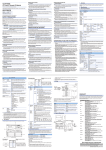
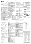
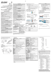
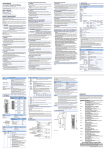
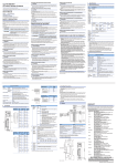
3. PART NAMES
This section explains the names of the components for the remote I/O
module.
5)
4)
3) 2)
1)
6)
7)
Connector for I/O
interface
Connecteur pour
interface E/S
4321
Pin
No.
4321
CON1
CON9
CON2
CON10
CON3
CON11
CON4
CON12
CON5
CON13
CON6
CON14
CON7
CON15
CON8
CON16
Signal
name
Broche
N°
Nom
de
signal
1
2
3
4
1
2
3
4
1
2
3
4
1
2
3
4
+24V
+V
24G
X0
+24V
+V
24G
X1
+24V
+V
24G
X2
+24V
+V
24G
X3
C
O
N
1
C
O
N
2
C
O
N
3
C
O
N
4
Pin
No.
Broche
N°
C
O
N
5
C
O
N
6
C
O
N
7
C
O
N
8
5
1
2
3
4
1
2
3
4
1
2
3
4
1
2
3
4
Signal
name
Nom
de
signal
Pin
No.
Signal
name
Broche
N°
Nom
de
signal
+24V C 1
+V
O 2
24G N 3
9 4
X4
+24V C 1
+V
O 2
24G N 3
X5 10 4
+24V C 1
+V
O 2
24G N 3
X6 11 4
+24V C 1
+V
O 2
24G N 3
X7 12 4
+24V
NC
NC
Y0
+24V
NC
NC
Y1
+24V
NC
NC
Y2
+24V
NC
NC
Y3
Pin
No.
Signal
name
Broche
N°
Nom
de
signal
1
2
3
4
C 1
O 2
N 3
14 4
C 1
O 2
N 3
15 4
C 1
O 2
N 3
16 4
+24V
NC
NC
Y4
+24V
NC
NC
Y5
+24V
NC
NC
Y6
+24V
NC
NC
Y7
C
O
N
13
Connector for CC-Link/LT interface
Connecteur pour interface
CC-Link/LT
Pin No.
Signal name
Broche N°
Nom de signal
1
+24V
2
DA
LINK/PW
6
3
DB
4
24G
No.
Item
Description
Confirmation details
On:
Power supply on.
PW
Off:
The power supply is turned off or the voltage drop
is too large.
On:
Normal communication.
L RUN
Off:
Communication cutoff
(time expiration error).
On:
Indicates that a communication data error has
occurred or the setting switch is outside the
allowable range.
Flicker at regular intervals:
Indicates that the setting switch has been changed
while current is being conducted.
(The module continues to operate even while the
L ERR.
LED is flickering. The changed settings will be
reflected when the power has been restored.)
Flicker at irregular intervals:
Indicates that the terminal resistor is left
unconnected or that the module or connection
cable are affected by noise.
Off:
Normal communication.
Displays the ON/OFF status of the input (turned on in the
0 to 7
ON status and turned off in the OFF status).
Displays the ON/OFF status of the output (turned on in the
0 to 7
ON status and turned off in the OFF status).
Specifies whether to maintain or turn off the output of the remote I/O
module in case the communication stops.
The switch is set to OFF at shipment from the factory.
ON: Maintain output
OFF: Turn output off
Set the response time (OFF→ON/ON→OFF time) of the remote I/O
module.
OFF is set as default (factory-set).
Noise may be taken in as input, if high speed response type is set.
Be sure to set response time in consideration of the environment.
ON: 0.5ms (High speed response type)
OFF: 1.5ms (Standard type)
Select "10", "20" or "40" to set the ten's place of the station number.
Select "1","2","4" or "8" to set the one's place of the station number.
All switches are set to OFF at shipment from the factory.
Always set the station number within the range of 1 to 64.
A setting error occurs and "L ERR." LED flickers if the value outside the
range 1 to 64 is set.
(Example) Set the switches as below when setting the station number to
32:
Ten's place
One's place
Station
40
20
10
8
4
2
1
number
(SW1) (SW2) (SW3) (SW4) (SW5) (SW6) (SW7)
32
OFF
ON
ON
OFF
OFF
ON
OFF
LED name
1)
Operating
status indicator
LEDs
2)
Output hold
setting switch *
(SW9)
3)
Response time
setting switch *
(SW8)
4)
Station number
setting
switches *
(SW1 to 7)
7
No.
5)
6)
7)
Item
Connector for
CC-Link/LT
interface
Connector for
I/O interface
Hook for
DIN rail
Description
Connector for connecting the CC-Link/LT communication line, module
power supply and load power supply.
Sensor connector for connecting output signals.
Hook for installing the module on a DIN rail.
*Set up using a slotted screwdriver with a tip width of 0.9 mm or less.
8
4. HANDLING PRECAUTIONS
(1) When using a DIN rail, attach the DIN rail after taking the following
items into consideration:
(a) Applicable DIN rail types (conform to JIS C 2812)
TH35-7.5Fe
TH35-7.5Al
(b) Interval between the DIN rail's installation screws
Tighten the screws using a pitch of 200mm (7.87in.) or less
when attaching a DIN rail.
(2) To attach the remote I/O module to the DIN rail, press the
centerline area of the DIN rail hook beneath the module until a click
is heard.
(3) When installing the remote I/O module into a panel, etc., provide
15mm (0.59 in.) or more of space between the top and bottom of
the module and other structures or parts so that good ventilation
and ease of operation when exchanging modules can be secured.
9
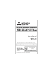
5. WIRING
5.1 External wiring
Câblage externe
Connector for
CC-Link/LT
interface
1
2
3
4
3-wire sensor
(Sink output)
(NPN output type)
2-wire sensor
(Sink output)
CL2XY16-DTP1C5V
Insulation
+24V
DA
DB
24G
Connector for
interface
CON1
1 +24V
2 +V
3 24G
4 X0
Direction
circuit
1
2
3
4
CON2
+24V
+V
24G
X1
1
2
3
4
CON8
+24V
+V
24G
X7
Direction
circuit
(Sink output)
Load
Load
Load
1
2
3
4
CON 9
+24V
NC
NC
Y0
CON 10
+24V
NC
NC
Y1
1
2
3
4
CON 16
+24V
NC
NC
Y7
1
2
3
4
Constant
voltage circuit
10
French
English
Connector for CC-Link/LT interface
Connecteur pour interface CCLink/LT
Insulation
Isolation
Connector for interface
Connecteur pour interface
3-wire sensor(Sink output)(NPN output
type)
Capteur 3-fils(Sortie
dissipateur)(type de sortie NPN)
2-wire sensor(Sink output)
Capteur fil-2(Sortie dissipateur)
Direction circuit
Circuit à direction
(Sink output)
(Sortie dissipateur)
Load
Charge
Constant voltage circuit
Circuit à tension constante
All +24V pin are connected within the module (common).
The module power and load power are supplied via the power adapter.
Toutes les broches +24V sont connectées à l'intérieur du module (commun).
L'alimentation du module et l'alimentation de la charge se font via l'adaptateur
d'alimentation.
11
5.2 Connection and wiring of the connector for I/O interface
Wire the connector for I/O Interface according to the following
procedure:
(1) Verify that the plug cover is installed in the plug unit.
Caution: Do not push the plug cover into the plug unit before the
cable is inserted.
Once a plug is pressure-displaced, it can no longer be
reused.
(2) Insert the cable until it makes contact with the plug unit.
Point
• When inserting the cable, confirm that it has been inserted completely.
If the cable is not ins+erted completely, it may cause contact failures.
• If the cross section of the cable is not round, the cable cannot be inserted smoothly. Cut
the cable tip using pliers, etc., and make it as round as possible, then insert it.
• When inserting the cable, the cable may stick out from the front of the cover. In such a
case, pull the cable backward so that the tip of the cable stays within the plug cover.
(3) Using a pliers or special tool, push the plug cover into the plug unit,
and pressure-displace it. After performing pressure displacement,
verify that the plug cover is securely attached to the plug unit, as
shown in the figure at right.
Point
While performing pressure displacement, the plug cover may rise because it is not latched
against the plug unit correctly. This condition indicates that pressure displacement is
incomplete. Push the plug cover until it is securely installed in the plug unit.
12
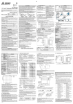
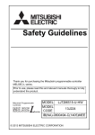
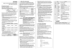
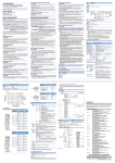
6. EXTERNAL DIMENSIONS
39 (1.54)
85 (3.35)
43 (1.69)
48 (1.89)
Center of DIN rail
4
(0.16)
4
(0.16)
Unit: mm (inch)
13
MEMO
14
WARRANTY
Mitsubishi will not be held liable for damage caused by factors found not to be the cause of
Mitsubishi; machine damage or lost profits caused by faults in the Mitsubishi products; damage,
secondary damage, accident compensation caused by special factors unpredictable by
Mitsubishi; damages to products other than Mitsubishi products; and to other duties.
Country/Region Sales office/Tel
Country/Region Sales office/Tel
USA
Mitsubishi Electric Automation lnc.
500 Corporate Woods Parkway, Vernon
Hills, IL 60061, USA
Tel : +1-847-478-2100
South Africa
CBI-Electric.
Private Bag 2016, ZA-1600 Isando,
South Africa
Tel : +27-11-977-0770
Brazil
MELCO-TEC Representacao Comercial
e Assessoria Tecnica Ltda.
Av. Paulista, 1439, cj74, Bela Vista,
Sao Paulo CEP: 01311-200-SP Brazil
Tel : +55-11-3146-2200
China
Mitsubishi Electric Automation (China) Ltd.
No.1386 Hongqiao Road, Mitsubishi
Electric Automation Center, Changning
District, Shanghai, China
Tel : +86-21-2322-3030
Germany
Mitsubishi Electric Europe B.V. German
Branch
Gothaer Strasse 8, D-40880 Ratingen,
Germany
Tel : +49-2102-486-0
Taiwan
Setsuyo Enterprise Co., Ltd.
6F., No.105, Wugong 3rd Road, Wugu
District, New Taipei City 24889, Taiwan,
R.O.C.
Tel : +886-2-2299-2499
UK
Mitsubishi Electric Europe B.V. UK Branch
Travellers Lane, Hatfield, Hertfordshire,
AL10 8XB, UK.
Tel : +44-1707-27-6100
Korea
Italy
Mitsubishi Electric Europe B.V. Italian
Branch
Viale Colleoni 7-20864 Agrate Brianza
(Milano), Italy
Tel : +39-039-60531
Mitsubishi Electric Automation
Korea Co., Ltd.
3F, 1480-6, Gayang-Dong, Gangseo-Gu,
Seoul, 157-200, Korea
Tel : +82-2-3660-9530
Singapore
Mitsubishi Electric Europe B.V. Spanish
Branch
Carretera de Rubi 76-80.AC.420, E-08190
Sant Cugat del Valles (Barcelona), Spain
Tel : +34-93-565-3131
Mitsubishi Electric Asia Pte, Ltd. Industrial
Division
307, Alexandra Road, Mitsubishi Electric
Building, Singapore, 159943
Tel : +65-6470-2308
Thailand
Mitsubishi Electric Automation (Thailand)
Co., Ltd.
Bang-Chan Industrial Estate No.111
Soi Serithai 54,
T.Kannayao, A.Kannayao, Bangkok
10230 Thailand
Tel : +66-2906-3238
Indonesia
P. T. Autoteknindo Sumber Makmur
Muara Karang Selatan, Block A / Utara
No.1 Kav. No. 11,
Kawasan Industri Pergudangan,
Jakarta-Utara 14440, P.O, Box 5045,
Indonesia
Tel : +62-21-663-0833
India
Mitsubishi Electric India Pvt. Ltd.
2nd Floor, Tower A & B, Cyber Greens,
DLF Cyber City, DLF Phase-III,
Gurgaon-122002 Haryana, India
Tel : +91-124-463-0300
Australia
Mitsubishi Electric Australia Pty. Ltd.
348 Victoria Road PO BOX11,
Rydalmere, N.S.W 2116, Australia
Tel : +61-2-9684-7777
Spain
France
Mitsubishi Electric Europe B.V. French
Branch
25, Boulevard des Bouvets, F-92741
Nanterre Cedex, France
Tel : +33-1-5568-5568
Czech Republic Mitsubishi Electric Europe B.V.-o.s.Czech
office
Avenir Business Park, Radicka 751/113e,
158 00 Praha5, Czech Republic
Tel : +420-251-551-470
Poland
Mitsubishi Electric Europe B.V. Polish
Branch
ul. Krakowska 50, 32-083 Balice, Poland
Tel : +48-12-630-47-00
Russia
Mitsubishi Electric Europe B.V. Russian
Branch St.Petersburg office
Piskarevsky pr. 2, bld 2, lit "Sch", BC
"Benua", office 720; 195027,
St. Petersburg, Russia
Tel : +7-812-633-3497
HEAD OFFICE : TOKYO BUILDING, 2-7-3 MARUNOUCHI, CHIYODA-KU, TOKYO 100-8310, JAPAN
NAGOYA WORKS : 1-14, YADA-MINAMI 5-CHOME, HIGASHI-KU, NAGOYA, JAPAN
When exported from Japan, this manual does not require application to the Ministry
of Economy, Trade and Industry for service transaction permission.
Specifications subject to change without notice.