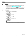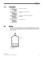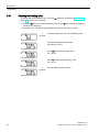
1
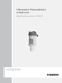
Ultrasonic Transmitters SITRANS LU150 Operating Instructions 03/2015 SITRANS Safety Guidelines Warning notices must be observed to ensure personal safety as well as that of others, and to protect the product and the connected equipment. These warning notices are accompanied by a clarification of the level of caution to be observed. Qualified Personnel This device/system may only be set up and operated in conjunction with this manual. Qualified personnel are only authorized to install and operate this equipment in accordance with established safety practices and standards. Unit Repair and Excluded Liability: The user is responsible for all changes and repairs made to the device by the user or the user’s agent. All new components are to be provided by Siemens Milltronics Process Instruments. Restrict repair to faulty components only. Do not reuse faulty components. Warning: Cardboard shipping package provides limited humidity and moisture protection. This product can only function properly and safely if it is correctly transported, stored, installed, set up, operated, and maintained. This product is intended for use in industrial areas. Operation of this equipment in a residential area may cause interference to several frequency based communications. Note: Always use product in accordance with specifications. Copyright Siemens AG 2013. All Rights Reserved Disclaimer of Liability This document is available in bound version and in electronic version. We encourage users to purchase authorized bound manuals, or to view electronic versions as designed and authored by Siemens Milltronics Process Instruments. Siemens Milltronics Process Instruments will not be responsible for the contents of partial or whole reproductions of either bound or electronic versions. While we have verified the contents of this manual for agreement with the instrumentation described, variations remain possible. Thus we cannot guarantee full agreement. The contents of this manual are regularly reviewed and corrections are included in subsequent editions. We welcome all suggestions for improvement. Technical data subject to change. MILLTRONICS®is a registered trademark of Siemens Milltronics Process Instruments. Contact SMPI Technical Publications at the following address: European Authorized Representative Technical Publications Siemens AG Siemens Milltronics Process Instruments 1954 Technology Drive, P.O. Box 4225 Peterborough, Ontario, Canada, K9J 7B1 Email: [email protected] Siemens AG Industry Sector 76181 Karlsruhe Deutschland For a selection of Siemens Milltronics level measurement manuals, go to: www. siemens.com/processautomation. Under Process Instrumentation, select Level Measurement and then go to the manual archive listed under the product family. For a selection of Siemens Milltronics weighing manuals, go to: www. siemens.com/processautomation. Under Weighing Technology, select Continuous Weighing Systems and then go to the manual archive listed under the product family. © Siemens AG 2013 SITRANS LU150 1 ___________________ Introduction 2 ___________________ Installation SITRANS Ultrasonic Transmitters SITRANS LU150 3 ___________________ Mounting 4 ___________________ Interconnection 5 ___________________ Operation ___________________ 6 Adjustments Operating Instructions ___________________ 7 Supplement ___________________ 8 Technical data 03/2015 A5E34590123-AA Legal information Warning notice system This manual contains notices you have to observe in order to ensure your personal safety, as well as to prevent damage to property. The notices referring to your personal safety are highlighted in the manual by a safety alert symbol, notices referring only to property damage have no safety alert symbol. These notices shown below are graded according to the degree of danger. DANGER indicates that death or severe personal injury will result if proper precautions are not taken. WARNING indicates that death or severe personal injury may result if proper precautions are not taken. CAUTION indicates that minor personal injury can result if proper precautions are not taken. NOTICE indicates that property damage can result if proper precautions are not taken. If more than one degree of danger is present, the warning notice representing the highest degree of danger will be used. A notice warning of injury to persons with a safety alert symbol may also include a warning relating to property damage. Qualified Personnel The product/system described in this documentation may be operated only by personnel qualified for the specific task in accordance with the relevant documentation, in particular its warning notices and safety instructions. Qualified personnel are those who, based on their training and experience, are capable of identifying risks and avoiding potential hazards when working with these products/systems. Proper use of Siemens products Note the following: WARNING Siemens products may only be used for the applications described in the catalog and in the relevant technical documentation. If products and components from other manufacturers are used, these must be recommended or approved by Siemens. Proper transport, storage, installation, assembly, commissioning, operation and maintenance are required to ensure that the products operate safely and without any problems. The permissible ambient conditions must be complied with. The information in the relevant documentation must be observed. Trademarks All names identified by ® are registered trademarks of Siemens AG. The remaining trademarks in this publication may be trademarks whose use by third parties for their own purposes could violate the rights of the owner. Disclaimer of Liability We have reviewed the contents of this publication to ensure consistency with the hardware and software described. Since variance cannot be precluded entirely, we cannot guarantee full consistency. However, the information in this publication is reviewed regularly and any necessary corrections are included in subsequent editions. Siemens AG Division Process Industries and Drives Postfach 48 48 90026 NÜRNBERG GERMANY Order number: A5E32243983 Ⓟ 01/2015 Subject to change Copyright © Siemens AG 2014. All rights reserved Table of contents 1 Introduction ............................................................................................................................................. 5 2 Installation .............................................................................................................................................. 7 3 4 5 6 7 2.1 Environmental ........................................................................................................................... 7 2.2 Location .................................................................................................................................... 7 Mounting ................................................................................................................................................. 9 3.1 3.1.1 Threaded ................................................................................................................................... 9 Flange adapter (optional) ........................................................................................................11 3.2 4" Sanitary ...............................................................................................................................12 Interconnection ..................................................................................................................................... 15 4.1 Cable entry ..............................................................................................................................15 4.2 System diagram ......................................................................................................................16 4.3 Wiring connection ...................................................................................................................16 Operation .............................................................................................................................................. 17 5.1 Start up ...................................................................................................................................17 5.2 Calibration ...............................................................................................................................18 5.3 Calibration: reference method ................................................................................................18 5.4 4 mA calibration ......................................................................................................................19 5.5 20 mA calibration ....................................................................................................................19 5.6 Operation status ......................................................................................................................20 Adjustments .......................................................................................................................................... 21 6.1 6.1.1 6.1.2 Calibration ...............................................................................................................................22 4 mA calibration ......................................................................................................................22 20 mA calibration ....................................................................................................................23 6.2 6.2.1 Blanking ..................................................................................................................................23 Adjusting the blanking value ...................................................................................................24 6.3 6.3.1 Speed of response ..................................................................................................................25 Adjusting the speed of response ............................................................................................26 6.4 6.4.1 Fail-safe ..................................................................................................................................26 Adjusting the fail-safe setting ..................................................................................................27 6.5 6.5.1 Fail-safe timer .........................................................................................................................27 Adjusting the fail-safe timer ....................................................................................................27 6.6 6.6.1 Units ........................................................................................................................................28 Adjusting the units ...................................................................................................................28 Supplement .......................................................................................................................................... 29 SITRANS LU150 Operating Instructions, 03/2015, A5E34590123-AA 3 Table of contents 8 7.1 Measurement interval ............................................................................................................ 29 7.2 Troubleshooting ..................................................................................................................... 30 Technical data ...................................................................................................................................... 31 8.1 Specifications ......................................................................................................................... 31 SITRANS LU150 4 Operating Instructions, 03/2015, A5E34590123-AA 1 Introduction Note For industrial use only This product is intended for use in industrial areas. Operation of this equipment in a residential area may cause interference to several frequency based communications. WARNING SITRANS LU150 is to be used only in the manner outlined in these operating instructions. The SITRANS LU150 is an ultrasonic level monitor combining sensor and electronics in a single package. It is designed to measure liquid levels in open or closed vessels. The process part (sensor) is PVDF, allowing the SITRANS LU150 to be used in a wide variety of industries, especially food and chemical. The sensor houses the ultrasonic transducer and temperature sensing element. The SITRANS LU150 emits a series of ultrasonic pulses from the transducer. Each pulse is reflected as an echo from the material and sensed by the transducer. The echo is processed by the SITRANS LU150 using Siemens Milltronic’s proven ‘Sonic Intelligence’ techniques. Filtering is applied to help discriminate between the true echo from the material, and false echoes from acoustical and electrical noises and agitator blades in motion. The time for the pulse to travel to the material and back is temperature compensated and then converted into distance for the mA output. SITRANS LU150 Operating Instructions, 03/2015, A5E34590123-AA 5 Introduction SITRANS LU150 6 Operating Instructions, 03/2015, A5E34590123-AA 2 Installation 2.1 Environmental The SITRANS LU150 should be mounted in an area that is within the temperature range specified, and that is suitable to the housing rating and materials of construction. It is advisable to keep the SITRANS LU150 away from high voltage or current runs, contactors and SCR control drives. 2.2 Location Locate the SITRANS LU150 so that it will have a clear sound path that is perpendicular to the liquid surface. ① ② ③ Sanitary ferrule Pipe The SITRANS LU150 sound path should not intersect the fill path, rough walls, seams, rungs, etc. ④ ⑤ Seams Fill Rungs SITRANS LU150 Operating Instructions, 03/2015, A5E34590123-AA 7 Installation 2.2 Location SITRANS LU150 8 Operating Instructions, 03/2015, A5E34590123-AA 3 Mounting 3.1 Threaded ① ② ③ Electronics Mounting thread Sensor SITRANS LU150 Operating Instructions, 03/2015, A5E34590123-AA 9 Mounting 3.1 Threaded The SITRANS LU150 is available in three thread types: 1. 2" NPT ((Taper), ANSI/ASME B1.20.1) 2. R 2" ((BSPT), EN 10226) 3. G 2" ((BSPP), EN ISO 228-1 Note Before inserting the SITRANS LU150 into its mounting hole, ensure that the threads are of the same type to avoid damaging the device. Note Mount the SITRANS LU150 so that the face of the sensor is at least 25 cm above the highest anticipated level. SITRANS LU150 10 Operating Instructions, 03/2015, A5E34590123-AA Mounting 3.1 Threaded 3.1.1 Flange adapter (optional) The SITRANS LU150 can be fitted with the optional 75 mm (3") flange adapter for mating to 3" ANSI, DIN 65PN10 and JIS 10K3B flanges. ① ② SITRANS LU150 Optional flange adapter SITRANS LU150 Operating Instructions, 03/2015, A5E34590123-AA 11 Mounting 3.2 4" Sanitary 3.2 4" Sanitary Note Mount the SITRANS LU150 so that the face of the sensor is at least 25 cm above the highest anticipated level. Note • The sanitary version is suitable for chemical clean-in-place applications to 60 °C (140 °F) only. Ensure your cleaning chemicals are compatible with PVDF. ① ② ③ Electronics Mounting thread Sensor Mounting the sanitary version 1. Mount the SITRANS LU150 onto the top of the tank’s sanitary ferrule. 2. Secure mating by surrounding the joint with the clamp. 3. Tighten adjusting wing nut. SITRANS LU150 12 Operating Instructions, 03/2015, A5E34590123-AA Mounting 3.2 4" Sanitary ① ② ③ SITRANS LU150 Clamp ④ ⑤ Ferrule Tank Adjusting wing nut 4" Sanitary ferrule Note The inside of sanitary ferrule must be smooth, and free of burrs, seams or ridges. SITRANS LU150 Operating Instructions, 03/2015, A5E34590123-AA 13 Mounting 3.2 4" Sanitary SITRANS LU150 14 Operating Instructions, 03/2015, A5E34590123-AA Interconnection 4.1 Cable entry 4 1. Loosen lid and remove it. 2. Install cable gland or conduit. 3. Insert wires through gland or conduit and up through cable guide. 4. Connect wiring. 5. Replace lid and tighten it. * Lid removed for clarity Note • To maintain IP and NEMA ratings, tighten the lid between 4 to 4.5 Nm. • Ensure the cable gland is screwed in to the enclosure tightly and the cable is within the specified clamping range (6.5 to 12 mm). • User supplied cable glands must meet IP68/NEMA 6 ratings and be installed according to the manufacturers instructions. SITRANS LU150 Operating Instructions, 03/2015, A5E34590123-AA 15 Interconnection 4.2 System diagram 4.2 System diagram ① ② 4.3 SITRANS LU150 Loop instrumentation Wiring connection ① ② ③ SITRANS LU150 ④ V supply Loop instrumentation R max Note Power supply is reverse polarity protected. SITRANS LU150 16 Operating Instructions, 03/2015, A5E34590123-AA 5 Operation 5.1 Start up 1. With the SITRANS LU150 correctly installed (or aimed at a wall 0.25 to 5 m away), apply power. The device starts up, displaying the following: • ① ② ③ ④ '4' key '20' key Program mode ⑤ ⑥ ⑦ Units LOE/fault Operation status Alphanumeric 2. It then defaults to the Run mode, which is the measurement reading of the distance from the transducer face to the material level in the units indicated as shown: 3. If the default display differs from that shown, refer to SITRANS LU150. SITRANS LU150 Operating Instructions, 03/2015, A5E34590123-AA 17 Operation 5.2 Calibration 5.2 Calibration The calibration of the mA output may be done such that its span will be either proportional or inversely proportional to the material level. Note The 4 and 20 mA levels may be calibrated in any order. 5.3 Proportional span Inversely proportional span high level = 20 mA high level = 4 mA low level = 4 mA low level = 20 mA Calibration: reference method 1. Adjust the material level (or target) to the desired distance from the sensor face. 2. Press the “4” or “20” key (as appropriate) to view the stored distance associated with that mA output value. 3. Press the key a second time to set the new distance reference. 4. After viewing or calibrating, the unit operation automatically reverts to the Run mode (6 sec). The calibration value is referenced from the face of SITRANS LU150 sensor, in the units displayed. SITRANS LU150 18 Operating Instructions, 03/2015, A5E34590123-AA Operation 5.4 4 mA calibration 5.4 4 mA calibration Press "4" Press "4" again 4 mA calibration calibration invalid if new 4 mA calibration retry 5.5 20 mA calibration Press "20" Press "20" again 20 mA calibration calibration invalid if new 20 mA calibration retry Note Calibration bypasses the measurement response rate. SITRANS LU150 Operating Instructions, 03/2015, A5E34590123-AA 19 Operation 5.6 Operation status 5.6 Operation status The graphic portion of the display gives the user a visual indication of the SITRANS LU150 operating status. During commissioning, viewing the graphic can assist the user in properly locating and installing the unit to achieve optimum performance. ① ② ③ GOOD WAITING LOE / FAULT The graphic will change from full to partial to indicate operation status. After the 'Waiting' period, the '?' icon will appear for an 'LOE / FAULT' indication. When a valid echo is again received, a 'Good' indication will resume. Refer to Troubleshooting (Page 30). SITRANS LU150 20 Operating Instructions, 03/2015, A5E34590123-AA 6 Adjustments There are several operating adjustments that can be made to the SITRANS LU150. To access the operating adjustments, simultaneously press the "4" and "20" keys until the desired adjustment is obtained. A viewing sequence of the stored value is automatically initiated. During this time the value can be changed by pressing either the "4" or "20" key. After viewing or changing, operation automatically reverts to the Run mode (6 secs). Adjustment Display 4 mA calibration (Page 22), scrolling 20 mA calibration (Page 23), scrolling Blanking (Page 23) Speed of response (Page 25) Fail-safe (Page 26) Fail-safe timer (Page 27) Units (Page 28) Note Calibration bypasses the measurement response rate. SITRANS LU150 Operating Instructions, 03/2015, A5E34590123-AA 21 Adjustments 6.1 Calibration 6.1 Calibration The 4 and 20 mA calibration values can be selected where reference levels, either from the material in the vessel or from a target, cannot be provided. This method can also be used to trim the output levels obtained by the Calibration: reference method (Page 18). To change the stored calibration value, obtain the 'c 4' or 'c 20' display. The calibration value may be increased by pressing the "20" key or decreased by pressing the "4" key. When the display has scrolled to the desired value, stop pressing the key. The display automatically reverts to the Run mode (6 secs). 6.1.1 4 mA calibration 4 mA calibration initiated view stored 4 mA calibration value (i.e. 4.50 m) press ”20” to increase to new calibration value (i.e. 4.60 m) new calibration value Note For faster scrolling, hold the key, and release it when the appropriate value is shown. SITRANS LU150 22 Operating Instructions, 03/2015, A5E34590123-AA Adjustments 6.2 Blanking 6.1.2 20 mA calibration 20 mA calibration initiated view stored 20 mA calibration value (i.e. 0.50 m) press ”4” to increase to new calibration value (i.e. 0.45 m) new calibration value 6.2 Blanking Blanking is used to ignore the zone in front of the transducer where false echoes are at a level that interfere with the processing of the true echo. It is measured outward from the sensor face. The minimum recommended blanking value is 0.25 m (0.82 ft) but can be increased in order to extend the blanking. ① ② SITRANS LU150 Blanking SITRANS LU150 Operating Instructions, 03/2015, A5E34590123-AA 23 Adjustments 6.2 Blanking 6.2.1 Adjusting the blanking value To change the stored blanking value, go to the 'bL' display (as described in Adjustments (Page 21)), and proceed as follows: 1. Press the "20" key to increase the blanking value, or the "4" key to decrease it until the correct value is displayed. 2. Release the key. The display automatically returns to the Run mode (6 secs). 3 seconds Indicates that the device is now in blanking mode. The stored blanking value is shown (for example 0.25 m) Press “20” to increase blanking value (i.e. 0.36 m) Press “4” to decrease the blanking value (i.e. 0.35 m) 6 seconds The new blanking value is shown. SITRANS LU150 24 Operating Instructions, 03/2015, A5E34590123-AA Adjustments 6.3 Speed of response 6.3 Speed of response The speed of response adjustment allows the user to collectively set a number of operating parameters. measurement response: is the limit to which the SITRANS LU150 will be able to keep up with rates of change. If the unit's measurement cannot keep up with the rate of level change, set the adjustment from '1' to '2'. If it still cannot keep up with the rate of level change, set the adjustment option to '3'. Avoid choosing an option that is too fast for your application. agitator discrimination: discriminates between agitator blades in motion, and the material (target) surface. filter: discriminates between false echoes from acoustical and electrical noise, and the material (target) surface. fail-safe timer: establishes the 'Waiting' period from the time a loss of echo or operating fault condition starts, until the fail-safe default is effected. Adjusting the speed of response will set the fail-safe timer to the default values in the chart. If a different response is required, adjust the ‘FSt’ option (Fail-safe (Page 26)). SP measurement response agitator discrimination filter fail-safe timer 1* 1 m/min (3.3 ft/min) on on 10 minutes 2 5 m/min (16.4 ft/min) on on 3 minutes 3 immediate off off 3 minutes 4 0.03 m/min (0.1 ft/min) on on 10 minutes * = factory setting SITRANS LU150 Operating Instructions, 03/2015, A5E34590123-AA 25 Adjustments 6.4 Fail-safe 6.3.1 Adjusting the speed of response To change the speed of response, go to the 'SP'' display (as described in Adjustments (Page 21)), and proceed as follows: 1. Press the "20" key to scroll forward through the available values (1-2-3), and press the "4" key to scroll backwards. 2. Once you have reached the appropriate value, stop pressing the key. The display automatically returns to the Run mode (6 secs). 3 seconds Indicates that the device is now in speed of response mode. The current option is shown (i.e. 1m/min) Press “20” for option 2 (i.e. 5 m/min) 6 seconds 6.4 Option 2 has now been selected. Fail-safe In the event a loss of echo or fault condition exceeds the 'Waiting' period (see Speed of response (Page 25), or Fail-safe timer (Page 27)), the '?' icon appears and one of the following fail-safe defaults is immediately effected. SP default mAp mAi reading 1 full 22 4 hold 2 empty 4 22 hold 3* hold hold hold hold p = proportional span i = inverseley proportional span * = factory setting SITRANS LU150 26 Operating Instructions, 03/2015, A5E34590123-AA Adjustments 6.5 Fail-safe timer 6.4.1 Adjusting the fail-safe setting To change the fail-safe setting, go to the 'FLS'' display (as described in Adjustments (Page 21)), and proceed as follows: 1. Press the "20" key to scroll forward through the available values (1-2-3), and press the "4" key to scroll backwards. 2. Once you have reached the appropriate value, stop pressing the key. The display automatically returns to the Run mode (6 secs). 3 seconds Indicates that the device is now in fail-safe mode. The current option is shown (i.e. full) Press “20” for option 2 (i.e. empty) 6 seconds 6.5 Option 2 has now been selected. Fail-safe timer The fail-safe timer allows the user to vary the ‘waiting’ period from the time a loss of echo or operating fault condition begins, until the fail-safe default is effected. The ‘waiting’ period is adjustable from 1 to 15 minutes, in 1 minute increments. The fail-safe timer value will default to settings determined by the Speed of response (Page 25). If a different value is desired, the fail-safe timer should be adjusted after the speed of response is set. 6.5.1 Adjusting the fail-safe timer To change the fail-safe setting, go to the 'FSt'' display (as described in Adjustments (Page 21)), and proceed as follows: 1. Press the "20" key to increase the 'waiting' period, and press the "4" key to decrease it. 2. Once you have reached the appropriate value, stop pressing the key. The display automatically returns to the Run mode (6 secs). SITRANS LU150 Operating Instructions, 03/2015, A5E34590123-AA 27 Adjustments 6.6 Units 6.6 Units The units of the measurement reading can be selected as follows: 1 = metres, m (factory setting) 2 = feet, ft The selected units are also applicable to the 'Blanking' adjustment. 6.6.1 Adjusting the units To change the units, go to the 'Un'' display (as described in Adjustments (Page 21)), and proceed as follows: 1. Press the "20" key to scroll forward through the available options (1-2), and press the "4" key to scroll backwards. 2. Once you have reached the appropriate value, stop pressing the key. The display automatically returns to the Run mode (6 secs). Indicates that the device is now in units mode. 3 seconds The current option is shown (i.e. m) Press “20” for option 2 (i.e. ft) Option 2 has now been selected. 6 seconds SITRANS LU150 28 Operating Instructions, 03/2015, A5E34590123-AA 7 Supplement 7.1 Measurement interval ① ② Interval (in seconds) mA loop current SITRANS LU150 Operating Instructions, 03/2015, A5E34590123-AA 29 Supplement 7.2 Troubleshooting 7.2 Troubleshooting The echo is not reliable and the SITRANS LU150 is waiting for a valid echo before updating the measurement. Probable causes are: • Material or object in contact with sensor face • The SITRANS LU150 is too close to the fill point • The SITRANS LU150 is not perpendicular to the liquid surface • Change in level too fast • Measurement out of range • Foam on liquid surface • High level of vibration in the mounting structure • Level inside the blanking zone The 'Waiting' period has expired. Investigate the probable causes listed above. Refer to Speed of response (Page 25) or Fail-safe timer (Page 27) for duration of 'Waiting' periods. SITRANS LU150 30 Operating Instructions, 03/2015, A5E34590123-AA 8 Technical data 8.1 Specifications Power Environmental 12 to 30 V DC (at terminal blocks), 0.1 A surge loop current: 4 to 20 mA max location: indoor / outdoor altitude: 2000 m max ambient temperature: continuous: relative humidity: suitable for outdoor (Type 6/NEMA 6/IP68 (2 meters for 24 hours)) installation category: I pollution degree: 4 -30 to +60 °C (-22 to +140 °F) -20 °C (-5 °F) if metal mounting Range 0.25 to 5 m ( 0.8 to 16.4 ft ) (liquids only) Beam angle 12° at -3 dB boundary Memory non-volatile EEPROM, no battery required Programming 2 tactile buttons Temperature compensation built-in to compensate over the operating range. Display liquid crystal three 9 mm (0.35") digits for reading of distance between sensor face and material multi-segment graphic for commissioning and troubleshooting mA output Construction range 4 to 20 mA span proportional or inversely proportional accuracy 0.25% of full scale at reference conditions resolution 3 mm (0.125") loading 600 ohms max loop load at 24 V DC supply cable Twisted pair, AWG 28 to 16 (0.34 to 1.5 mm) or equivalent combined sensor and electronics package sensor housing: material: PVDF mounting: threaded 2" NPT ((Taper), ANSI/ASME B1.20.1) R 2" ((BSPT), EN 10226) G 2" ((BSPP), EN ISO 228-1 4" Sanitary optional flange adapter material PBT connection 1 x M20 or 1/2" NPT conduit entry 2 screw terminal block for 2.5 mm2 (14 ga) solid wire / 1.5 mm2 (16 ga) stranded wire max SITRANS LU150 Operating Instructions, 03/2015, A5E34590123-AA 31 Technical data 8.1 Specifications Enclosure rating Type 6/NEMA 6/IP68 (2 meters for 24 hours) Weight 1.3 kg Approvals CE, CCSAUS SITRANS LU150 32 Operating Instructions, 03/2015, A5E34590123-AA www.siemens.com/processautomation For more information www.siemens.com/level www.siemens.com/weighing Siemens Canada Limited Siemens Milltronics Process Instruments 1954 Technology Drive P.O. Box 4225 Peterborough, ON Canada K9J 7B1 email: [email protected] Subject to change without prior notice A5E34590123 Rev. AA © Siemens AG 2014 www.siemens.com/processautomation *A5E34590123* Printed in Canada