Transcript
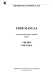
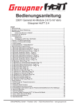
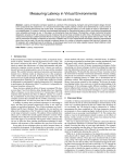
08 Programmable Items
01 Declaration
USER MANUAL
ATTENTION
Platinum 100A-HV-V3
“*”in explanations below indicate factory defaults.
1, Brake: *Off / Soft / Hard / Very hard
have no control over the correct use, installation, application, or maintenance of our
2, Battery Type: *LiPo / NiMH
products, no liability shall be assumed nor accepted for any damages, losses or costs
3, Cutoff Mode: *Soft cut / Hard cut. Soft means gradually reduce the output power. Hard means cut off the output immediately.
resulting from the use of the product. Any claims arising from the operating, failure or
4, Low-voltage Cutoff Threshold: Off / Low / *Middle / High / Customized: 16.8-50.4V,Step: 0.1V .
malfunctioning etc. will be denied. We assume no liability for personal injury, property
damage or consequential damages resulting from our products or workmanship.
CAUTIONS
Attention! It is necessary to reset the throttle range when using a new ESC or changed another transmitter.
RC models can be very dangerous, so please read this manual carefully. In that we
Thanks for purchasing our Electronic Speed Controller (ESC). High power system for
Brushless Electronic Speed Controller
13 Set The Throttle Range
As far as is legally permitted, the obligation to compensation is limited to the invoice
2 seconds later, the motor
emits 2 short “beep-beep-”
indicating the top position
is calibrated successfully.
Move the throttle stick to the bottom
position, await 1 second
then the bottom position
is calibrated Successfully.
14 Parameters Programming / setting Via The Transmitter
on the LCD program box to connect the ESC to a PC, then set relevant parameters via a special program (Hobbywing USB Link Software).
5, Flight Mode: Airplane Fixed Wing / Heli Governor Off / *Heli Governor (Elf) / Heli Governor Store
II, Select Items
After entered the “programming” mode, you can hear 12 sets of tone repeat
sequentially. Move the throttle stick to the bottom position in 3 seconds after the
motor emitted certain set of tone, and then you enter the corresponding item.
1. Brake
(1 short)
“B”
2. Battery Type
(2 short)
“BB”
3. Cutoff
(3 short)
“BBB”
4. Low-voltage Cutoff Threshold (4 short)
“BBBB”
5. Flight Mode
(1 long)
“B—”
6. Auto Rotation Restart Time
(1 long & 1 short)
“B—B”
7. Timing
(1 long & 2 short)
“B—BB”
8. PWM Frequency
(1 long & 3 short)
“B—BBB”
9. BEC Voltage
(1 long & 4 short)
“B—BBBB”
10.LiPo Cells
(2 long)
“B—B—”
11. Reset to Factory Default
(3 long & 1 short)
“B—B—B—B”
12.Exit
(3 long & 2 short)
“B—B—B—BB”
Note: Generally 1 long “Beep—” equals to 5 short “beep-”, e.g, in step II “Select
Items” , 1 long & 1 short (“Beep—Beep”) represents option 6.
4 steps to set parameters via the throttle stick:
1) Airplane Fixed Wing: The motor starts to spin at 5% throttle, then speeds up quickly and reaches the full speed from standstill in 300µs. In this mode, the ESC will be enforced to set the “Auto
I, enter “programming” mode,
II, select item(s),
Rotation Restart Time” to “OFF”.
III, select option(s) / parameters under item(s),
2) Heli Governor Off: When the motor starts at 5% throttle, the startup is very soft and it takes 11 seconds to reach the full speed from standstill. In this mode, if the transmitter is in NORMAL state,
IV, exit “setting”.
then usually the throttle curve is a slash (the start point is the lowest point / 0% throttle, the end point is the highest point / 100% throttle of the throttle range. And this throttle curve is often used
by beginners). As the start point is only 5% of the full throttle, the motor rotates slowly that greatly reduces psychological pressure for beginners, so pilots can select this mode for basic practices like
I, Enter “Programming / Setting” Mode
1. Turn on the transmitter, move the throttle stick to the top position (full throttle);
2. Connect battery to the ESC, then the motor emits “♪ 123” indicating the ESC is powered on normally .
3. 2 seconds later, the motor emits two short “beep-beep- ”;
..
4. 5 seconds later, the motor emits “♪ 56712” indicating it’s already entered the “programming” mode.
“frog leap”. In this mode, the ESC will automatically set the “Auto Rotation Restart Time” to “Off”.
3) Heli Governor (Elf) & Heli Governor Store:The motor only starts at 40% (or above) throttle (in governor mode, the motor won’t start when the throttle value is within 0%-40%); its startup is very
soft and needs 11 seconds to reach the full speed from standstill. Besides, it has speed-governing function (works at 40%-100% throttle). As the motor rotates quickly in “governor” mode, so it isn’t
suitable for beginner anymore but experienced pilots. In these two modes, the setting about “Auto Rotation Restart Time” comes into effect (please refer to “Auto Rotation Restart Time” for more
• High-performance microprocessor with the operating frequency up to 50MHz brings excellent compatibility (with most motors in the market) and high driving efficiency.
information).
• The maximum motor speed can reach 210000 RPM (for 2-poles), 70000 RPM (for 6-poles) and 35000 RPM (for 12-poles).
4) Heli Governor (Elf) & Heli Governor Store have different ways of storing target rev data. In “Governor Store” mode, the data are saved into the FLASH of the microprocessor (and the data won’t
• Multiple flight modes: Airplane Fixed Wing / Heli Governor Off / Heli Governor (Elf) / Heli Governor Store.
disappear after powered off); while in “Governor (Elf)” mode, data of the nominal target rev are saved into the RAM of the microprocessor (and the data will disappear after powered off).
• Adjustable throttle range, compatible with various transmitters. It brings smooth, soft & linear speed adjustment and rapid throttle response.
III, Select Options / Parameter Values
The motor beeps in loops, move the throttle stick to the top position when heard some “beep(s)” tone
. .
indicating you selected its corresponding option value; then the motor will sound “♪ 1515” means the
value has been saved. (And if you don’t want to set other items but quickly exit “setting”, please move the
throttle stick to the bottom position in 3 seconds ; while if you still want to set other items, please wait for
returning to Step II and choose other items.
• In “Governor (Elf)” mode, the ESC will automatically start the RPM standardization & regain the target rev data after powered on.
• Microprocessor powered by independent DC regulator has better anti-interference performance, which greatly reduces the risk of losing control.
• In “Governor Store” mode, if it needs to re-standardize the target RPM, pilots must modify and save the flight mode as any option except "Heli Govornor Store"first (without restarting the ESC at
• Brand new governor program, easy to operate; and its excellent speed-governing effect can make big rotor blades more stable even under rapid load change.
this moment), then modify and save it as "Heli Govornor Store"; the ESC will enter the RPM standardization and regain the target RPM data after it’s powered on. After the first activation of the
• "Restart in auto rotation" can manually interrupt the auto rotation and quickly restart the motor to avoid crashes caused by incorrect operations.
“speed-governing” function or changed accessories (like motor, battery cells amount, gear and different type of main/big rotor blades) on the plane, pilots need to standardize the RPM again next time.
• Independent output port for RPM (that is: motor speed) signals.
Here we suggest pilots take the “Governor Store” mode as their first option to avoid standardizing rev every time.
• Compatible LCD program box (optional accessory), its simple and visual interface allows users to set/revise all the ESC parameters easily.
a) RPM standardization in “Governor (Elf)” mode: when the throttle value switches to over 40% from 0%, the motor
(For detailed information, please refer to User Manual of LCD Program Box.)
starts in a super soft way and accelerates slowly; it completes RPM standardization in 11 seconds and then enters the
• Upgradeable firmware, you can upgrade the ESC after connecting it to a PC via the USB cable on the program box.
• The independent port, for connecting the program box and setting parameters, can also be the output port of the running status data of the ESC. When coordinating with the data transmission module,
it can make the real-time data monitoring and logging possible.
“governor” mode. After changed batteries, the ESC will standardize the RPM again.
-100%
After flight, please move the transmitter throttle stick to the bottom position, the motor stops spinning and the ESC will
50%
50%
100% Throttle
Stick
Position
-100%
(“*” in the form below indicate factory defaults)
100% Throttle
Stick
Position
12°
12°
FLASH, so there is no need to standardize the rev again.
Neutral
Point
Airplane
Fixed Wing
c) Example for RPM Standardization:
In this example, we take the neutral point (50%) of the throttle stick as reference points for standardizing RPM.
Model
Platinum-100A-HV-V3
Main Application
550-600 classes helicopter (600-620mm blade)
Input
5-12S LiPo, 16.8-50.4V
IV, Exit “Setting”
Two ways to exit “setting” mode:
a) In Step III, after heard the special tone
. .
“♪ 1515” while selecting optional
values, move the throttle stick to the
bottom position in 2 seconds, then you
exit “setting”.
b) After heard 3 long & 2 short beeps
which represent item 12 while selecting
options in Step II, move the throttle
stick to the bottom position in 3
seconds, then you exit “setting”.
Pitch(IDLE)
Pitch(NORMAL)
save the standardized (target) RPM into the FLASH. After changed batteries, the ESC will read the target RPM from the
03 Specifications
Throttle (IDLE)
100%
Neutral
Point
“governor” mode.
• The anti-spark circuit on the input wires eliminates the electro spark created when connecting the battery pack to the ESC.
Throttle (NORMAL)
100%
b) RPM standardization in “Governor Store” mode: when the throttle value switches to over 40% from 0%, the motor
starts in a super soft way and accelerates slowly; it completes RPM standardization in 11 seconds and then enters the
• Multiple protection features including input voltage abnormality protection / low-voltage cutoff protection / throttle signal loss protection effectively prolong the service life of the ESC.
Then a long “beep”
indicates the system
is ready and you can
fly the aircraft now.
3.00V /3.25V. For example, when using 8S LiPo, if this programmable item is set to “middle”, the cutoff threshold of this battery pack will be 3.00×8=24.00V.
2) When set as “NiMH battery”, then the low / middle / high cutoff voltage is 50% / 62.5% / 75% of the initial input voltage (at boot/starting up) . For example, when using a 20-cell NiMH battery pack,
3) When set as “Customized: 16.8-50.4V”, the cutoff threshold of the battery pack can be precisely set (the precision can reach 0.1V). But you need a LCD program box (optional accessory) or USB cable
02 Features
The motor emits N
beeps to indicate
the amount of
Lipo cells.
1) When set as “LiPo battery”, the ESC will automatically calculate the cutoff threshold of the battery pack according to the amount of LiPo cells. The low / middle / high cutoff voltage per cell is 2.75V /
the voltage at starting up is 1.44×20=28.8V; and if this programmable item is set to “low”, the cutoff threshold of this battery pack will be 28.8×50%=14.4V.
amount of the affected product.
Connect battery to the
ESC, and the motor emits
“♪123” indicating the ESC
is powered on normally.
Turn on the transmitter,
and move the throttle
stick to the top
position (full throttle).
• Set the throttle curve (throttle value at the neutral point=50%) & pitch curve (the pitch at the neutral point is 0) in
“NORMAL” mode, and keep the throttle HOLD switch “locked” to ensure safety.
Neutral
Point
-100%
100% Throttle
Stick
Position
-100%
Neutral
Point
100% Throttle
Stick
Position
• Connect the fully charged battery to the ESC, let the ESC complete the initialization, then move the transmitter
throttle stick to the neutral point (here the throttle value at the neutral point is 50% and the pitch of main rotor
The example of throttle curve and pitch curve for RPM standardization
Cont. / Burst Current
Cont. 100A / Burst 140A (in 10 sec)
BEC
Without built-in BEC
Programming Port
The programming port can provide 5.5V/100mA power supply to the program box or the external cooling fan
Throttle Signal and RPM signal
Signal transferred via optoelectronic coupler
5) As the battery voltage decreases & the pitch of main rotor blades varies in flight, so we recommend setting the throttle curve between 60%~85% (here we strongly suggest not set the value exceeds
Input / output Wires
Input:12AWG / Output:12AWG
85%) on the transmitter to guarantee the speed -governing effect and sufficient compensating room to keep the motor’s constant speed. If still can’t reach that target rev when the throttle value
Weight/Size
104g / 77x35x21mm(without cooling fan), 110g / 77x35x32mm(with cooling fan)
blades is 0 degree), and then “unlock” the throttle HOLD switch; the motor will start from standstill in a super soft
Note: After revised ESC parameters via the
transmitter throttle stick or program card/box, please
save those settings and exit; then the motor emits 5
long “beep-“ and 5 seconds later you can restart the
ESC.
Without built-in BEC
5 cells
way, accelerate slowly and completes the target rev standardization 11 seconds later.
6 cells
8 cells
10 cells
12 cells
• Trial flight. If the target rev is too low, then raise the throttle curve; if the target rev is too high, and then lower the throttle curve. E.g. set the throttle curve in IDLE1 / IDLE2 / IDLE3 mode to 65% /
75% / 85% respectively to experience different RPM, and then adjust the value according to the actual situation or preference.
exceeds 85%, please change the motor pinion.
6) For guaranteeing the speed-governing effect, we strongly recommend setting the PWM frequency as 32 kHz.
15 ESC Programming Sample
In the example below, it set the “flight mode” to “Heli Governor Off” , that is the 2nd parameter of item 5.
6, Autorotation Restart Time: Off / 5s / *10s / 15s / 30s / 90s.
04 Wiring Diagram
Platinum-100A-HV-V3
This parameter is only used in “Governor (Elf)” and “Governor Store” modes, and works when the throttle value is within 5%~40%.
I, Enter “programming” mode:Move the throttle stick to
II, Select items: motor starts to
III, Select Options:motor emits a short
IV, Exit “setting”:
During the period of auto rotating (to land), pilots still have the chance to cancel the operation by interrupting the process and restarting the motor quickly. E.g. when set the parameter to 10 seconds,
the top position and then turn on the transmitter, connect
sound, when heard a long “beep—”
“beep-“, 3 seconds later, two short
After the 3rd step
enabling the throttle HOLD switch (to activate the throttle protection) in flight, the motor will cut off the output and let the helicopter land. While, if you want to end this process immediately, then you
ESC to battery, the motor emits “♪ 123” indicating it’s
(which represent Item #5—flight
“beep-beep-“, then move the throttle stick
completed, move the
need to “unlock” the HOLD switch (to exit the throttle protection) and increase the throttle value to over 40%, and the ESC will temporarily switch the acceleration time to 1.5 seconds (that is: it
mode), move the throttle stick to the
bottom position, then you entered
to the top position, and the motor emits
. .
“♪ 1515” indicating it has set to “Heli
throttle to the bottom
reaches the full speed from standstill in 1.5s) and output power quickly. This action protects the helicopter from crashing caused by the motor’s slow acceleration. However, if “lock” the throttle HOLD
normally powered on. 2 seconds later, it emits “beep-beep-”
..
and then 5 seconds later it emits “♪ 56712 ” which indicates
switch over 10 seconds, the ESC will still output power slowly at a super soft acceleration rate (that means it will take 11s to reach the full speed from standstill) even if you “unlock” the throttle HOLD
it’s already entered the “programming” mode.
this item
Governor Off”.
seconds.
position again in 2
switch and increase the throttle value promptly.
Security Warning: For safety, please pay attention to the following points.
• When the landing process ends early and the helicopter gets back to ground before the “autorotation restart time”, it’s prohibited to “unlock” the throttle HOLD switch before disconnecting the
battery. Otherwise, the helicopter may rotate and accelerate to a high speed in 1.5s and cause accidents. E.g., if “unlock” the throttle HOLD switch in the “Auto rotation restart time” with the
helicopter is still in “IDLE” mode, main rotor blades will spin rapidly and the helicopter may drift and tilt even on the ground.
Battery
16 Troubleshooting
• If switch the flight mode from “IDLE” to “NORMAL” and move the throttle stick to the bottom position (0% throttle) or “lock” the “Throttle Cut” switch on the transmitter, main rotor blades will not
Trouble
rotate even if you accidentally “unlocked” the throttle HOLD switch.
• In “governor” mode, if set “Auto Rotation Restart Time” to “Off”, the motor will always restart at the super soft acceleration rate (it takes 11 seconds to reach the full speed from standstill). Please
attention!
Motor
7, Advanced Timing: 0deg / 4deg / 8deg / 12deg / *15deg / 18deg / 22deg / 26deg / 30deg / Customized: 0deg~30deg, step: 1 deg.
In general, the low timing works fine for most motors. While as great differences exist among motors, so please try different timing(s) to get the best driving effect. For increasing the speed, you can set
Cause
Solution
After powered on, the motor doesn’t rotate and there is no sound emitted.
Poor connection between power connectors.
Re-plug or change the connectors.
After powered on, the motor doesn’t spin, but emits the warning tone
“beep beep, beep beep, beep beep” (the interval between each group of
“beep beep” is 1 second).
The battery voltage is abnormal.
Please check the battery voltage.
No signal output from the throttle channel of the receiver.
Please check whether the communication between the transmitter
& receiver is normal or not, and if the control wire (that is, Rx wire) has
been firmly plugged into the throttle channel in the correct direction.
After powered on, the motor doesn’t run but emits “beep, beep, beep,
beep, beep” (each beep is very short and hurried).
After powered on, the motor doesn’t run but emits “beep-beep” then the
..
special tone “♪ 56712 ”.
Didn’t move the throttle stick to the bottom position or
the throttle range is too narrow.
Move the throttle stick to the bottom position or reset the throttle range.
Incorrect “Normal / Reverse” direction of the throttle channel.
Please refer to the transmitter’s user manual and reset the “Normal /
Reverse” direction of the throttle channel.
The motor rotates in the wrong direction.
Connected ESC output wires to motor wires in the wrong order.
Swap any of two wire connections.
Throttle signal loss protection is activated.
Please check the communication between the transmitter & receiver,
and also check the connection between ESC and the receiver.
Low-voltage cutoff protection is activated.
Charge the battery pack or change a new one.
Poor wire connections.
Please check the battery connector and the connection between ESC
output wires and motor wires.
the timing higher. After the timing adjustment, we recommend having a trial on the ground first, and then fly in the sky.
After powered on, the motor doesn’t spin but emits the warning tone
8, PWM Frequency: 8KHz / 16KHz / 24KHz / *32KHz
“beep-, beep-, beep-” (the time interval each “beep-” is 2 seconds).
The rise of PWM frequency can make the motor driving smoother and the noise lower; certainly, this will bring more switching loss for the MOSFET & more heat to the ESC.
RPM Signal Output
9, BEC Voltage: This programmable item is invalid for Platinum-100A-HV V3 ESC as there is no built-in BEC in this ESC.
10, LiPo Cells: *Auto calculation / 5S / 6S / 8S / 10S / 12S
Receiver
The parameter is valid only when the battery pack is LiPo. After powered on, the ESC will make the motor beep the amount of cells in your LiPo pack according to auto-detection or cell count
manually set.
The operation of anti-spark connectors.
• The tricolor (WRB) cable here is the throttle cable (throttle signal is transferred via optoelectronic coupler)
There are a pair of bullet connectors and a thin red wire attached to the
(WHITE: throttle signal wire, RED: Not used in this ESC, BLACK: ground wire);
• The thin Orange wire is for RPM signal output (the RPM signal is also transferred via optoelectronic coupler);
positive input wire (red color, thick) of the ESC. They eliminate sparks when
• The 3-pin port (marked with - + P) is an independent port for parameter setting; it can connect LCD Program
the battery pack is connecting to the ESC. Please follow the sequence
09 Begin To Use A New Brushless Esc
The motor stops halfway.
Box, or be the output port of the ESC running status data. 2 pins corresponding to “+” & “-” in the program port
below:
can provide 5.5V/100mA power supply to the LCD program box or the external cooling fan.
1. Disconnect the two bullet connectors on the positive input wire (red
Before using a new ESC, you need to check all the connections to make sure they are correct and reliable before connecting the ESC to the battery. When ensured everything is ok, then start the
color, thick) of the ESC.
ESC in the following sequence:
Note: Please ONLY use the cooling fans made by Hobbywing technology Co, ltd. Other
2. Connect battery to the ESC.
1, Move the throttle stick to the bottom position (throttle value=0%), then turn on the transmitter;
cooling fans may damage the built-in 5.5V DC regulator because of over-load.
3. Connect the bullet connectors on the positive input wire (red color, thick)
2, Connect the battery pack to the ESC, then the ESC starts self-test; the motor issues “♪ 123” indicating the system is powered on, and N short “beeps” indicating the amount of LiPo cells of
ATTENTION
of the ESC as soon as you hear the special tone “♪123”.
the battery pack, then a long “beep—“indicating the self-test is completed successfully and the system is ready to fly.
DEVELOPER’S GUIDE
• If no response is received, please check the battery and battery connections to ensure they are ok and reliable.
(Note: This guide is only for developers, common users needn’t read it.)
• If the motor doesn’t beep after powered on, it means the battery voltage is too low or too high. Please check the battery voltage.
05 Output Port For RPM Signals
..
• If the motor sounds “beep-beep-” 2 seconds after powered on, and “♪ 56712 ” 5 seconds later to indicate the ESC is entering the “programming” mode, it means the throttle channel
direction in your transmitter is reversed, in such a case you need to reset the “Normal / Reverse” direction of the throttle channel by referring to the transmitter’s manual.
To ensure the ESC fits well with the throttle range on your transmitter, you need to reset the throttle range when using this ESC for the first time or
Platinum V3 series speed controllers have independent output ports / interfaces for RPM signals, so it can connect to flybarless systems like Mikado V-Bar as RPM signal source. Undoubtedly, this reduces
peripheral devices which need to be connected to the flybarless helicopter and simplifies the wiring.
ATTENTION
changed another transmitter for the optimum throttle linearity. For detailed operation, please refer to the explanation in 《Set the Throttle Range》.
【Output the real-time running data of the ESC】
The PLATINUM V3 series of ESC has independent port for connecting the LCD program box and output the running status data of the ESC via the SCI (Serial Communication interface). When coordinating
with the data transmission module, they can make the real-time data monitoring and logging possible.
Here, we open this functionality to the public so users can redevelop this ESC to expand its application fields.
When motor rotates, the parameter setting port works as single-way mode SCI (Serial Communication Interface), the baud rate is 19200bps. The port outputs 1 data package (/frame) every 20 milliseconds.
The format of each data frame is shown as below:
06 Output The Real-time Running Status Data Of The ESC
1
First Byte
10 Explanations For Warning Tone
Platinum V3 series speed controllers have independent ports for parameter setting, which can also be the output ports of the running status data of the ESCs. When coordinating with the data transmission
For more information, please read detailed explanations in 《Developer’s Guide》.
1. Warning tone for abnormal input voltage: when powered on the ESC, it will start testing the input voltage. If the voltage is not in the normal scope, the motor will emit the warning
Option
Item
1
3
4
Hard
Very hard
1
Brake
*Off
Soft
2
Battery Type
*LiPo
NiMH
3
Cutoff Mode
*Soft cut
Hard cut
4
Low-voltage
Cutoff Threshold
5
Flight Mode
6
Auto Rotation Restart Time
7
5
6
9
10
*Middle
High
Customized:
16.8-50.4V, Step:0.1V
Airplane Fixed Wing
Heli Governor Off
Off
5sec
*10sec
15sec
30sec
Advanced Timing
0deg
4deg
8deg
12deg
*15deg
8
PWM Frequency
8KHz
16KHz
24KHz
*32KHz
9
BEC Voltage
10
Lipo Cells
18deg 22deg 26deg 30deg
Without built-in BEC
6 cells
8 cells
10 cells
12 cells
Customized:
0deg-30deg, Step:1deg
10
Last Byte
0x9B
0xXX
0xXX
0xXX
0xXX
0xXX
0xXX
0xXX
0xXX
0xXX
it’s 128, the throttle signal received from the receiver is 50% of the maximum.
• Actual Output PWM: throttle signal value actually output by the ESC. Its high octet is also temporarily set at 0, and the valid range of the low octet is 0~255, that means the entire output range
(0~100%) is equally divided into 255 parts.
• Actual RPM Cycle: actual electric RPM signal cycle of the motor (µs).
to the bottom position again and restart. (Causes to this problem: poor wire connection between the ESC and the motor or disconnection of some output wire, propellers are blocked by other
For example: The actual rev of a 8-pole motor is 600 RPM, then its electric rev is 600 x 8 ÷ 2 = 2400RPM, which means the ESC commutates 2400 times in 60 seconds to drive the motor,
and the commutation cycle = 60 ÷ 2400 = 0.025s = 25000µs. Therefore, the decimal digit represented by the actual RPM Cycle is 25000.
【Output Port for RPM Signals】
objects, gears are blocked and cannot move and etc.)
• Platinum V3 series of speed controllers have independent output ports for RPM signals.
to 50% to ensure that the motor still has some power for avoiding crash caused by insufficient power. And the ESC will gradually resume its maximum power after the temperature returns to
• Specification for interface signals: It is the periodic signal with duty ratio of 17%, and 0V for low level, 3.3V for high level.
the safe level.
• It represents the electric rev of the brushless motor (electric rev means the rev of a 2-pole brushless motor). And here is the formula used for converting the actual rev of multi-pole brushless motor into
the electric rev of 2-pole brushless motor:
Electric rev = Actual rev of the multi-pole brushless motor × Pole number ÷2
4. Overload Protection: The ESC will cut off the power or restart automatically when the load suddenly increases to a very high value. And the common cause of load soar is the lockout of propellers.
90sec
9
means the entire throttle range (0~100%) is equally divided into 255 parts. For example, when the low octet value is 85, it means the throttle signal got from the receiver is 33% of the maximum; when
high-speed rotation of propellers or rotor blades.
*Heli Governor (Elf ) Heli Governor Store
8
• Rx Throttle Value: throttle signal value got from the receiver. Now, the “high octet of the Rx throttle value” is temporarily set at 0, and the valid scope of the low octet of Rx Throttle Value is 0~255, that
3. Throttle Signal Loss Protection: When detected the signal loss for over 0.25 second, the ESC will cut off the output immediately to avoid even greater loss which may caused by the continuous
Low
5 cells
8
7
• Package Number: number of each data package.
2. Overheat Protection: When the internal operating temperature exceeds 110 Celsius degree, the ESC will reduce its output power and start protection; it won’t cut off the output, but reduce it
Off
*Auto calculate
7
6
3. Warning tone if the throttle stick is not at the bottom position when the ESC is powered up: When the throttle is not at the bottom position, the ESC will issue the following warning:
1. Startup Protection: the ESC will shut down the motor after failed to start the motor normally in 2 seconds by increasing the throttle value, then you need to move the transmitter throttle stick
2
5
2. Warning tone for throttle signal loss: when detected no throttle signal, the ESC will issue the following warning: “beep-, beep, beep-” (the time interval among these “beeps” is 2 seconds).
11 Explanation For Other Protections
“*”in the form below indicate factory defaults.
4
• Package Head: Each data package ( / frame) is always started with the code “0x9B”.
“beep-beep-beep-beep-beep-” (every “beep” is very short and hurried).
07 Programmable Items
3
Package Head Package Number Package Number Package Number Rx Throttle Value Rx Throttle Value Actual Output PWM Actual Output PWM Actual RPM Cycle Actual RPM Cycle
High Octet
Mid Octet
Low Octet
High Octet
Low Octet
High Octet
Low Octet
High Octet
Low Octet
“beep beep, beep beep, beep beep” till the voltage returns to normal (the time interval among each group of “beep beep” is 1 second).
module, it can make the real-time data monitoring and logging possible.
2
E.g. the actual rev of a 12-pole motor is 5000rpm, so its corresponding electric rev is: 5000 × 12 ÷ 2 = 30000rpm
【ESC throttle Rang & Throttle Signal Specification】
12 Normal Start-up Process
• Factory default of the ESC throttle range is 1100 ~1940µs, the acceptable minimum time of high level is 815µs and the acceptable maximum time of high level is 2256µs. The acceptable minimum signal
cycle equals to the high level time (µs) plus 10µs.
• In PPM throttle signals, only signal cycle & high level time impact; changes of the high level time correspond to the notion of throttle value (0%~100%), here whether the low level time changes or not is
Turn on the transmitter and move the
Connect battery to the ESC, the
Then motor emits several short
And a long “beep” indicating the
throttle stick to the bottom position
motor will emit “♪123” indicating the
“beeps” to indicate the amount
system is ready and you can fly the
(Throttle value=0%).
ESC is powered on normally.
of LiPo cells.
helicopter or airplane now.
not taken into consideration.
• Different manufacturers have varied definitions of the high level time of throttle signal. For FUTABA radio system, it is 1100µs~1940µs and 1520µs is the midpoint (or so called “neutral point”); while for
JR radio system, it’s 1100µs~1900µs and the midpoint is 1500µs.
• The receiver outputs analog signals, and the ESC converts the analog signals into 8 to 12bits digital signals (the resolution for 8 bits is 0~255, and it is 0~4095 for 12 bits.).
• Because of the above differences exist among different radio systems; so it’s necessary to calibrate the throttle range on the ESC if users want to utilize the whole throttle range of the transmitter.