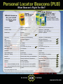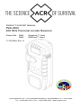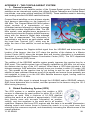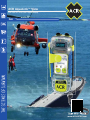
1
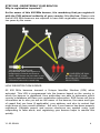
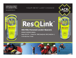
ACR AquaLink™ View 406 MHz GPS With New Digital Display PLB www.ACRARTEX.com ACR AquaLink™ View 406 MHz GPS Personal Locator Beacon Head offshore with confidence. With three levels of integrated signal technology — GPS positioning, a powerful 406 MHz signal, and 121.5 MHz homing capability — the AquaLink™ View quickly and accurately relays your position to a worldwide network of Search and Rescue satellites, reducing search time and increasing your chances of survival. It’s reliable signaling technology that has saved more than 30,000 lives since 1982. The AquaLink™ View broadcasts a unique registered distress signal that not only tells rescuers where you are, but who you are. The onboard GPS can fix your position to within 100 meters and then utilizes a powerful 406 MHz signal to relay your distress call to orbiting satellites. As local Search and Rescue is deployed, a separate homing signal and integrated LED strobe light guide rescuers to your exact location. The AquaLink™ View sports a digital display that allows you to see all of the beacon’s operational activities. The screen displays GPS LAT/LON, operating instructions, usage tips, transmission bursts as well as battery power. The digital display also makes self-testing your beacon simple and easy to understand by visually walking you through the self test step by step. No more relying on listening to beeps and looking for LEDs. The AquaLink™ View is small enough to be easily carried in a pack or pocket or can be worn on deck, at the helm, in quarters or on a life vest and will float if accidentally dropped overboard. Performing a full functional self test of the PLB’s internal circuitry, battery voltage & power, and 406 MHz transmission gives you peace of mind knowing your PLB will work the moment you need it most. ACR Exclusive: Built-in GPS acquisition test mode allows you to test GPS functionality up to 60 times over the life of the battery. Tap in to the same field-tested rescue technology used by the U.S. Military, U.S. Coast Guard, NATO Special Forces and Arctic explorers. SPECIFICATIONS Product Number 2884 Model Number PLB-350 C Size 2.3 x 5.8 x 1.45” (5.8 x 14.8 x 3.7 cm) Weight 9.2 oz (261 g) with lanyard Battery, Class Class 2 (non-hazmat) lithium batteries • No Subscription Fees • Floats Battery, Replacement Interval Replacement due six (6) years from date of manufacture or five (5) years after beacon is placed into service, whichever is first, or after emergency use • Super Bright LED Strobe • Built-in Digital Display Battery, Operational Life Exceeds 24 Hours @ -4°F (-20°C) • On Board 66 Channel GPS Battery, Typical Performance 30 Hours @ -4°F (-20°C) Battery, Storage -40°F to + 158°F (-40°C to +70°C) Material Engineered polycarbonate blend Color ACR-treuse™ (high visibility yellow) Activation Manual Operation 2 steps: deploy antenna, press ON button. Give clear view of sky Waterproof 16.40 ft (5 m) @ 1 hr., 33 ft (10 m) @ 10 min. Factory tested @ 70°F, exceeds RTCM waterproof requirements Radiated Power 6.3W (406 MHz), 50 mW +/-3dB (121.5 MHz) Accessories Attachment clip included Approvals Cospas-Sarsat, FCC, Canada, R&TTE 5.8” • Self-Test and GPS Test Features • Typical Performance 30 Hours • Non-Hazmat Battery • Made in the U.S.A 2.3” 1.45” Limited Warranty 5 years Lead Free Yes For further information please contact: It is mandatory that you register your PLB. It’s fast, easy and free www.beaconregistration.noaa.gov. When activated, the unique identification code in your PLB is linked to the registration database. This way authorities can retrieve valuable information about you and your trip. ACR Electronics, Inc. 5757 Ravenswood Road Fort Lauderdale, FL 33312 The AquaLink™ View is a satellite signaling device of last resort, for use when all other means of self rescue have been exhausted, where the situation is grave and imminent loss of life, limb, eyesight, or valuable property will occur without assistance. Tel: (954) 981.3333 Fax: (954) 983.5087 Email: [email protected] © 2012 ACR Electronics, Inc. 03/12 www.ACRARTEX.com Personal Locator Beacons (PLB) What Beacon’s Right For Me? Buoyant 406link.com** Made in USA Most Powerful Twice as likely to reach satellites in bad weather Sma Small Non Buoyant Low Power Which beacon on do you want nt to save your ur life? Manufacturer McMurdo, Based in UK ACR, Based in Fort Lauderdale, FL Product / Model FastFind / 210 AquaLink™ / PLB-350 B AquaLink™ View / PLB-350 C $299.99 $399.99 - $499.99 Street Price (plus $24.99 flotation pouch and $19.99 lanyard) Frequency 406 MHz / 121 MHz Homing 406 MHz / 121 MHz Homing GPS 50 Channel Receiver 66 Channel Receiver Digital Display No Available on AquaLink™ View Power Output 4.3 Watts* 6.3 Watts* Location Accuracy 110 Yards 110 Yards Size/Weight 1.3 x 1.9 x 4.2" / 5.3 oz 1.5 x 2.3 x 5.8" / 9.2 oz Notification Time 2-15 Minutes 2-15 Minutes Activation Manual Manual Typical Battery Life 24-40 Hours 30-35 Hours Waterproof Testing 33 Ft. (10m) for 5 minutes 33 Ft. (10m) for 10 minutes Buoyant Will not float (Pouch, sold separately) Yes- Self Buoyant Strobe Light Manual, Maximum 30 Operations Automatic, Continuous During Activation Antenna Single Use Blade Reusable Blade Lanyard No, sold separately Yes NEW - Advanced Satellite self test No, self test cannot reach satellites Yes, with 406Link.com** NEW - Advanced Satellite GPS self test No, self test cannot reach satellites Yes, with 406Link.com** Product Warranty 5 Years 5 years *From Cospas-Sarsat test results **Optional subscription fee required for non-distress messaging capabilities THE SCIENCE OF SURVIVAL www.acrartex.com PRODUCT SUPPORT MANUAL PLB-350C 406 MHz Personal Locator Beacons Product No.: 2884 2885 (AquaLink™ View) (SARLink™ View) Y1-03-0244, Rev. H ACR Electronics, Inc. // 5757 Ravenswood Road // Fort Lauderdale // FL // 33312-6645 Tel: +1 (954) 981-3333 // Fax: +1 (954) 983-5087 // www.acrartex.com About ACR Electronics ACR Electronics www.acrartex.com, designs and manufactures a complete line of safety and survival products including EPIRBs, PLBs, AIS, SARTs, Strobe Lights, Life Jacket Lights, Search Lights and safety accessories. The quality systems of this facility have been registered by TUV to the AS9100C/ISO 9001:2008 Series Standards. Recognized as the world leader in safety and survival technologies, ACR has provided safety equipment to the aviation and marine industries as well as to the military since 1956. CAUTION: Before proceeding to install, test or use your new ACR Electronics’ product, please read this Product Support Manual in its entirety. If you have questions regarding the contents of the manual or something not covered in the manual, please contact our Technical Service Department at ACR Electronics, Inc., Telephone +1 (954) 981-3333. You can also visit our website at www.acrartex.com and access the Frequently Asked Questions (FAQs) section for further information. If in the future you lose this manual, you may access and print a replacement on the ACR website. Y1-03-0244H 2 Table of Contents STEP ONE - REGISTERING YOUR BEACON _____________________ 4 STEP TWO - HOW THE BEACON WORKS ______________________ 6 STEP THREE - MAINTAINING YOUR PLB ______________________ 15 APPENDIX A - ACCESSORIES _______________________________ 19 APPENDIX B - USER INTERFACE: SPECIAL ICONS ________________ 20 APPENDIX C - USER INTERFACE: DIGITAL DISPLAY DURING OPERATION ____________________________________________ 21 APPENDIX D - USER INTERFACE: DIGITAL DISPLAY DURING SELF-TEST ______________________________________________________ 24 APPENDIX E - USER INTERFACE: DIGITAL DISPLAY DURING EXTENDED GPS TEST ______________________________________________ 27 APPENDIX F - THE COSPAS-SARSAT SYSTEM ___________________ 28 APPENDIX G - TECHNICAL SPECIFICATIONS ____________________ 29 APPENDIX H - WARRANTY, NOTICES _________________________ 30 APPENDIX I – RESTRICTIONS ON USE ________________________ 31 PLEASE READ ALL WARNINGS, CAUTIONS AND NOTES CARFULLY Y1-03-0244H 3 STEP ONE - REGISTERING YOUR BEACON Why is registration important? As the owner of this 406 MHz beacon, it is mandatory that you register it with the PLB national authority of your country: It is the law. Please note that all 406 MHz beacons are required to have their registration updated every two years by the owner. Your personalized ID code programmed inside each beacon is transmitted to Search and Rescue (SAR). SAR forces use this code to pull up your registration to find out valuable information about who needs help. YOUR RESCUE WILL BE DELAYED IF YOUR BEACON ISN’T PROPERLY REGISTERED! HOW REGISTRATION WORKS: All 406 MHz beacons transmit a Unique Identifier Number (UIN) when activated. This UIN is programmed into the beacon based on the country in which the beacon is registered, thus authorities are able to determine which country’s database will have your registration information. SAR forces will have information as to who you are as the owner of the beacon, the name and type of vessel that you have (if applicable), your address, and who to contact that might know of your current situation - but only if your beacon has been properly registered. Valuable search and rescue resources are wasted every year responding to false alerts, and registering your beacon helps to resolve this quickly. Y1-03-0244H 4 What country should I register in? The beacon must be registered in the country of the owner’s residence. If the beacon is not programmed to that country’s code and protocol, and the residence is outside of the USA, the beacon needs to be reprogrammed. Additionally, the beacon must be reprogrammed if you, as the owner, move out of the country where the beacon is registered. To verify the country for which a beacon is programmed, see the label with the UIN (Unique Identification Number) on the back of the unit. How do I register? Registration in the United States The national authority that accepts registrations in the United States is the National Oceanic and Atmospheric Administration (NOAA). There are three ways to register: 1. The fastest and easiest way www.beaconregistration.noaa.gov/. to register is online at 2. Faxing a registration is also acceptable. Fax the registration form to the fax number on the top of the registration form. NOTE: Do not confuse the registration form with the ACR Electronics warranty card. 3. If online or fax registration is not available, mail the registration form with the pre-addressed, postage paid envelope to: SARSAT Beacon Registration NOAA NSOF, E/SPO53 1315 East West Hwy Silver Spring, MD 20910-9684 All registration forms will be entered in the 406 MHz beacon registration database within 48 hours of receipt. The information you provide on the registration form is used for rescue purposes only. A confirmation letter, a copy of the actual registration and a proof-of-registration decal will be mailed to you within two weeks. When you receive these documents, please check the information carefully, and then affix the decal to your beacon in the area marked “BEACON DECAL HERE.” It is very important that the proof of registration decal matches the UIN on the beacon. If you do not receive confirmation back from NOAA within two weeks, call toll free (888) 212-7283 for assistance. Y1-03-0244H 5 Registration in Canada Canadian residents can register online at: http://canadianbeaconregistry.forces.gc.ca/ or contact the Canadian Beacon Registry by phone at: 877-406-7671 or by fax at: 877-406-3298. Canadian registration forms can also be mailed to: Canadian Beacon Registry CFB Trenton, PO Box 1000 Stn Forces Astra, Ontario K0K 3W0 Registration in Other Countries In countries other than the United States and Canada, 406 MHz beacons are registered with that country’s national authority at the time of purchase. The sales agent may have assisted you in filling out the forms and sending them to the country’s national authority. Alternatively, many countries allow online registration in the International 406 MHz Beacon Registration Database (IBRD) at www.406registration.com. To verify that the unit is properly programmed for your country, view the UIN label on the back of the unit. In the event that the beacon is not programmed for your country, the sales agent (if properly equipped) can reprogram the unit for the correct country. STEP TWO - HOW THE BEACON WORKS NOTE: Please be aware that, throughout your user manual, reference is made to the beacon ‘BEEPING’. Please note that the ‘beeps’ are of a very high pitched tone that some people are unable to hear. Be aware that the beeps are not the indication of a fully functional beacon but only a guidance to Technicians and Engineers to troubleshoot the unit. 1. How your beacon summons help 406 MHz beacons are a type of portable emergency equipment that transmits a distress signal to search and rescue (SAR) organizations. The purpose of these beacons is to aid SAR teams in tracking and locating ships or individuals in jeopardy as rapidly as possible. The 406 MHz frequency is a worldwide dedicated emergency frequency that is detected by a network of satellites called the Cospas-Sarsat system. This satellite system was established by, and continues to be supported by, its primary benefactors - the USA, Russia, Canada and France. The CospasSarsat system has saved over 28,400 lives - and counting - since its inception. See Appendix or the Cospas-Sarsat website for more information about the system at www.cospas-sarsat.org. Y1-03-0244H 6 When a 406 MHz beacon is activated, the digital distress message is sent to Cospas-Sarsat satellites and, in turn, the distress message is relayed to SAR. The distress message contains the beacon UIN and on some models the GPS location of the beacon. Additional information about the beacon is accessed by SAR from the beacon registration database. At the same time the 406 MHz signal is activated, a 121.5 MHz signal is turned on. The 121.5 MHz signal is used by SAR to home in on the beacon as they approach it. The 406 MHz signal is detected by multiple satellites and from that information the location of the beacon can be calculated. This data alone is sufficient for SAR to find persons or ships in distress in a reasonable timeframe. However, as a further enhancement, some beacons have a GPS engine onboard. This feature allows the beacon to acquire current location coordinates from an internal GPS receiver. The purpose of this feature is to send an even more precise location of the beacon to the satellites, i.e., latitude and longitude data. This helps SAR to reach the location even faster. 2. Internal GPS position system The PLB-350C is fitted with an internal GPS receiver that will download the coordinates (latitude and longitude) of the beacon’s position on the globe, to be transmitted to the Cospas-Sarsat emergency system. When the beacon is activated, the internal GPS immediately attempts to acquire positional coordinates. GPS coordinates can be acquired any time that the GPS is on, but only valid data is saved. Once the beacon acquires valid coordinates, the data is included as part of the next transmitted 406 MHz digital message. The internal GPS operates on a schedule during a beacon activation. The GPS is on for a time, actively acquiring coordinates, and off for 20 minutes, in a standby state. The schedule is designed to conserve battery but, at the same time, assure that navigational coordinates are regularly updated. 3. Optional beacon management and testing services Additional features and through satellite testing services are available for this beacon when you subscribe to the SafeLife System. When you sign up for this optional service you can test your beacon and have confirmation messages sent to your cell phone or email. Expanded services also will include friends and family contact information for check in messaging. Visit 406Link.com for complete details. (This service is not required for your beacon to function as a Personal Locator Beacon.) Y1-03-0244H 7 4. Anatomy of your beacon Digital display Antenna: Wrapped around beacon FRONT BACK UIN Label: Applied at the factory, the 15 character hexadecimal number is unique to each beacon. Multi-language label: This optional label may be applied for ease of use. Antenna latch Activation button cover Registration decal supplied by some countries: Once the beacon is registered, the label goes here. Keypad GPS antenna location Battery expiration label with the month/ year the battery needs to be replaced. Figure 1 NOTE: The appearance of your beacon may vary from this picture. Y1-03-0244H 8 5. Distinguishing PLB Features The distinguishing features available on your PLB vary with the particular model that you selected. The following table summarizes the similarities and differences in models. PLB-350C Product names ACR Product Number Unique features GPS engine Top case Buoyant Included Accessories Optional Accessories AquaLink™View 406 GPS PLB 2884 SARLink™ View 406 GPS PLB 2885 Digital display, LED strobe, 60 GPS acquisition tests Internal, 66-channel GPS receiver Clear Yes No Multi-Function Belt Clip Flotation pouch (ACR P/N 9504) 6. Digital Display The digital display in the beacon is used as a secondary visual aid, supporting the green/red LED and the audio tone, which indicate the status of the beacon during testing and during emergency operation. The messages on the digital display typically appear as one or two words at a time, until the entire message has been displayed. PLB ON Y1-03-0244H When the beacon is activated, the display will show the message PLB ON. The beacon will begin to send 406 MHz emergency signal bursts, at which time the display provides other messages including 406 SENT, 121.5 ON and GPS coordinates, provided the data was acquired. If GPS data has not been successfully downloaded into the beacon, the digital display will give you tips like “GIVE CLEAR VIEW TO SKY.” GPS √ 9 In Self-Test, the display illustrates the test result of each step with “√” indicating a pass and “X” indicating a failure. There are a total of five tests, including a battery check. If all tests pass, SELF-TEST PASS will be displayed at the end of the Self-Test mode. In the GNSS Self Test mode, the digital display will show the letters “GPS Test” moving left to right while the internal GPS receiver is acquiring the coordinate data. Once the data is acquired, the coordinates will display as a confirmation that the data was successfully acquired. This will be followed by the GPS coordinates horizontally scrolling through the display, provided the beacon has successfully downloaded an external GPS location. See Appendixes B through E for details about display messages. 7. Activating your beacon Warning: This transmitter is authorized for use only during situations of grave and imminent danger. Deliberate misuse may incur a severe penalty. Overview Personal Locator Beacons are designed to be manually activated. They are only to be activated when all other means of self-rescue have been exhausted. When properly registered as required, the activation of the beacon tells Search and Rescue who you are, where you are, and that you are facing a life threatening situation. Y1-03-0244H 10 NOTE: The appearance of your key pad may vary from this picture. Activation diagram ON / OFF Button (visible only when antenna is deployed) When activated: (Flashing Red LED) transmitting 406 MHz during activation (Flashing Green LED) 406 MHz includes GPS data (IR LED) Programming Interface (Not owner accessible) GPS Self-Test Button Self-Test Button PLB-350C Figure 2 - Key Pad Functions NOTE: If you notice the PLB is flashing the red or green LED and “beeping” periodically on its own, this likely means it has accidentally been activated and needs to be shut off and reported as a false alert see section on false alerts. Y1-03-0244H 11 Steps to activate (406 MHz and 121.5 MHz) To activate your beacon in a distress situation, follow these steps (see Figure 3 below). 1) Unclip the antenna from the case. 2) Move it into the upright position 3) Depress the ON/OFF ( ) button for 1 full second. You will see the Red LED flashing and the display reads “PLB ON”. Your beacon is now activated. While transmitting your distress signal, the red LED will flash once every 2 seconds, alerting you that your beacon is active. Figure 3 8. 406 MHz/121.5 MHz antenna position For maximum performance you must deploy the beacon antenna into the proper position as shown in Figure 3. If at all possible, be sure the antenna is positioned facing the sky and avoid submerging in water. This device is intended to operate on or above the ground or while attached to your person above the water line. 9. Activation with GPS If your unit is activated, the GPS receiver will start up, search to find your LAT/LON and incorporate it into your 406 MHz signal. As soon as the GPS receiver acquires valid positioning data, the red LED will stop blinking and the green LED will begin flashing once every 2 seconds. Y1-03-0244H 12 The same GPS data will be sent with each 406 MHz signal for the next twenty minutes. At that time the internal GPS will start up again, search to find your LAT/LON and incorporate it into your next 406 MHz signal. If for any reason the internal GPS cannot update your LAT/LON, your last position will be used for the next four hours. At that time the green LED will stop blinking and the red LED will flash once every 2 seconds until new GPS data is obtained. 10. GPS receiver orientation When activated, it is critical that you do not cover the beacon with any body part, water, clothing, etc. The GPS receiver is located under the bottom portion of the case behind the ACR Electronics’ logo (see Figure 4). To ensure optimum performance of the GPS receiver, the beacon needs to have an unobstructed view of the sky. Avoid submerging the GPS receiver in water if possible. Water will shield and inhibit the GPS receiver and may cause difficulties obtaining your GPS coordinates. Avoid leaning over the beacon to view blinking LED as you may shield the GPS reception. Figure 4 – GPS Receiver Location 11. Turning off the beacon To deactivate your beacon; depress the ON/OFF ( ) button for more than 4 seconds. Once the beacon is deactivated, all blinking LED’s will stop, signifying that the beacon is no longer sending your distress message. If deactivation should fail, remove the six screws holding the unit together and unplug the battery to disable the unit. Return the beacon to ACR Electronics for service. NOTE: Leave beacon on until rescued. Turning beacon off will prolong or prevent rescue. Repeated activations could be viewed as a hoax. Y1-03-0244H 13 12. Preventing false alerts A false alert is any activation of the beacon, intentional or otherwise, that does not result from a situation of grave and imminent danger. Be sure to do the following to help minimize false alerts: // Register your beacon. This does not reduce false alert rates; however, when the beacon is properly registered, the situation can usually be resolved with a phone call. // Be careful with whom you leave your beacon. Make sure that they know how to use it, and that they understand the ramifications of causing a false alert. A lot of false alerts are generated by curious individuals. If you notice the beacon is flashing the red or green LED and “beeping” periodically on its own, this likely means it has accidentally been activated and needs to be shut off and reported. // Do not stow beacon while other gear is in contact with the keypad. The Cospas-Sarsat satellites detect distress beacon transmissions immediately and locate the transmission within a few minutes of beacon activation. NOTE: If you report a false alert and the authorities have not received the signal, do not be concerned. This may mean that you were able to deactivate the beacon before transmitting the signal. 13. False alert A false alert must be reported to the search and rescue authorities. False alerts in the USA that are rectified must be reported to the US Air Force Rescue Coordination Center (AFRCC) to let them know that the situation has been corrected and everything is fine. Responsibly reporting these events to the AFRCC or your proper authority will not incur a penalty, but deliberate misuse or not notifying the proper authority may incur a severe penalty. Reporting Should there be a false alert for any reason, it must be reported to the nearest search and rescue authorities. The information that should be reported includes: // The PLB 15-digit Unique Identifier Number (UIN) // Time and date // Duration and cause of activation // Location of beacon at the time of activation Y1-03-0244H 14 To report false alert in the United States, contact the AFRCC: United States Air Force Rescue Tel: 1-800-851-3051 Coordination Center (AFRCC) To report false alerts outside of the USA, contact the national authority where your beacon is registered. STEP THREE - MAINTAINING YOUR PLB 1. Routine Maintenance Carefully inspect the beacon case for any visible cracks. Cracks may admit moisture, which could falsely activate the beacon or otherwise cause a malfunction. Any cracks observed should be immediately referred to ACR for evaluation by calling +1 (954) 981-3333. ACR Technical Support can also be reached by sending an email to [email protected]. After checking the beacon case for cracks, it may be wiped down with a clean, damp cloth. Do not use any type of cleaner on your beacon. 2. Battery Replacement Replace the battery no later than 6 years from date of manufacture, 5 years from date of install, or after emergency use. At each inspection, check the time remaining until replacement is required. The battery should be replaced if the beacon has been activated for any use other than the Self-test. Always refer battery replacements and other beacon service to a factory authorized Battery Replacement Center. Battery replacement includes servicing the beacon by replacing all o-rings, testing the water seal and the electrical properties. NOTE: There are no user serviceable items inside the beacon. DO NOT OPEN THE BEACON. Opening the beacon will void the warranty. For the nearest location of a Battery Replacement Center, visit our website at www.acrartex.com. Click on “Battery Replacement Center”. This beacon contains two (2) lithium metal battery packs that are less than 2 grams each. They are not classified as Hazmat for transportation. Prior to shipping beacon for service, alert your carrier about the batteries contained in this equipment to make sure they properly label your package. Call ACR’s Technical Service department at +1 (954) 981-3333 for proper shipping instructions or visit the ACR website in the Support section entitled “Hazmat, MSDS Sheets, & Info”. Y1-03-0244H 15 3. Self-test ACR strongly recommends performing the Self-test once per month, or at least two weeks prior to a trip allowing enough time for service should your beacon require it. A Self-test is initiated by holding the Self-test button for at least ½ second and less than 5 seconds. Your beacon will flash the green LED to signify the test has begun and the Digital Display will show Pass or Fail message. The green LED will flash a second time to indicate that the self test was successful. Components Tested: Data Integrity and Memory; 406 MHz Synthesizer; RF Power/Battery; GPS header If a red LED flashes at the completion of the Self-test, your beacon has failed. Repeat the Self-test. If the failure persists, contact ACR Electronics or an authorized Battery Replacement Center for servicing of your beacon. NOTE: During a Self-test your beacon will send a 406 MHz signal coded as Self-test to the satellite system. The 121.5 MHz homing signal is inhibited during Self-test; this allows you to test your beacon any time during the day without causing false alerts. Self Test Sequences Green LED, Display 4 Passes, Green LED Green LED, Less than 4 Passes, Red LED Red LED, Display 4 Passes, Green LED Red LED, Less than 4 Passes, Red LED Self Test Guide ( Red LED) Green LED Successful Self-test Failed Self-test – Return beacon to ACR Successful Self-test – At least 1 hour of battery power has been depleted, have battery replaced. Failed Self-test – Return unit to ACR for service. 4. Battery Witness Seal Life If your beacon flashes an initial red LED at the beginning of the Self- test, this indicates that your electronic witness has been broken and you have used more than 1 hour of battery life. While the beacon will still operate normally in a distress situation, ACR strongly recommends you have your battery replaced and the electronic witness reset to ensure that you will have 24 hours of battery power. Y1-03-0244H 16 5. GPS Testing (GNSS Self-Test) This test is NOT required as 100% of all GPS receivers that leave ACR have been tested to ensure they perform correctly. However, if you would like to ensure your GPS receiver is working, please follow these instructions very closely. CAUTION: For PLB-350C models, the following test cannot be performed more than sixty times during the life of the battery pack. Once this GPS testing feature reaches 60 times, the feature will be disabled by internal software. NOTE: The GPS receiver is located under the bottom front portion of the case. It is imperative that the receiver is not obstructed during Self-test or activation to ensure that the GPS receiver is acquiring your latitude (LAT) and longitude (LON) position. This test must be performed outside with a clear view of the sky. Press the GPS button for longer than 5 seconds. Observe the beacon for the entire GPS test. A green LED will indicate that the GPS has been turned ON. The beacon GPS will remain ON until LAT/LON coordinates have been obtained or until 2 minutes have elapsed. If good LAT/LON data has been obtained, a single 406 MHz test burst will be sent out with location data and the GPS will be turned OFF and the green LED will light for at least 3 seconds. This LAT/LON data is not saved for use. The green LED indicates that the GPS is functioning properly and that the beacon is in a location or environment where it can receive the necessary signals from satellites. If the GPS does not acquire good LAT/LON data, the GPS will turn OFF after 2 minutes, followed with a RED LED light up for 3 seconds, and no 406 MHz burst sent out. GPS Test Sequences duration 121 seconds) (maximum GPS Test Guide Green LED at start followed by “GPS TEST” displayed, Green LED and LAT/LON displayed Successfully acquired GPS data, 406 MHz burst sent out with location data Green LED at start followed by “GPS TEST” displayed, Red LED GPS data was successfully acquired, burst sent out. Y1-03-0244H not no 17 6. Changing ownership or contact information As the owner of the beacon, it is your responsibility to advise the national authority of any change in your registration information. If you are transferring the beacon to a new owner, you are required to inform the national authority. You can do this by using their online database or by letter, fax or telephone and informing the authority of the name and address of the new owner. The new owner of the beacon is required to provide the national authority with all of the information requested on the registration form. This obligation transfers to all subsequent owners. See earlier section, STEP ONE, for further details on this process. 7. Lost or stolen PLBs If your PLB is lost or stolen, do the following immediately: // Report to your local authorities that the PLB has been lost or stolen // Contact NOAA at (888) 212-7283 (212-SAVE), or your national authority, with the following information: o Police department name o Police department phone number o Police case number If your PLB were to be activated, the information you provided will be forwarded to the appropriate search and rescue authorities who will ensure that your PLB gets back to you. If someone attempts to register a PLB reported as stolen, NOAA or your national authority will notify the appropriate police department. Y1-03-0244H 18 APPENDIX A - ACCESSORIES 1. Multi-Function Belt Clip The SARLink™ View comes standard with a multifunction belt clip. To install the clip, simply align the bottom tabs on the clip with the insert holes located on the bottom of the beacon. Snap the clip in place by pressing the top of the clip so that the two top tabs engage in the two insert holes on the top of the beacon (see Figure 5). To remove the clip, push up and back on the top tabs one at a time to disengage the clip from the beacon. The belt clip has been designed to accommodate your extreme adventures. Figure 5 - Belt Clip You can secure your beacon directly to backpack webbing straps, life jackets or belts to ensure the beacon is close at hand. ACR recommends that you secure your beacon someplace on your person that is easily accessible in case of an emergency for rapid activation. Ensure the beacon is secured firmly and is protected before heading out to avoid damage or loss. NOTE: ACR recommends that once you have clipped your beacon in place that you also anchor the beacon with the lanyard to your life jacket, backpack, etc. to ensure the unit will not be lost if it should break out of the clip. Y1-03-0244H 19 APPENDIX B - USER INTERFACE: SPECIAL ICONS Characters displayed during beacon operation include the following: The battery gauge appears on certain screens to indicate the remaining level of battery charge The gauge illustrates the remaining charge in the battery as a percent of the total possible charge, e.g., The gauge will show the system to be charged in the following increments: 100, 75, 50 and 25%. The frequency transmission symbol appears on certain screens to indicate that the transmission has been sent G R The symbols for a green or a red LED light, respectively Indicates scrolling text Y1-03-0244H 20 APPENDIX C - USER INTERFACE: DIGITAL DISPLAY DURING OPERATION The following chart describes the audio-visual feedback the beacon provides during activation. The messages on the digital display typically appear as one or two words at a time, until the entire message has been displayed. AuquaLink™ View and SARLink™ View display, LED/ Audio Signaling and Description of Operation R R The beacon has been activated and the ACR Electronics Welcome Page appears PLB ON The system reports that the beacon is on and in activation mode GPS ON The system reports that the beacon has turned on the GPS engine GIVE CLEAR VIEW TO SKY The system reminds you that for optimum GPS performance, i.e., greatest likelihood of acquiring coordinates, position the beacon so that it has a clear view of the sky. DO HOLD NOT AERIAL The system reminds you that for optimum transmission of the emergency message, allow the beacon to float and do not hold the antenna (aerial). 406 SENT G R The system reports that the 406 MHz emergency message has been sent. If this message accompanied by a green LED flash, the GPS coordinates have been sent as well. If accompanied by a red LED flash, the GPS coordinates have not been sent. NOTE: If GPS coordinates were not sent, the system will continue to attempt to acquire the data and add it to the 406 MHz distress signal when available. Updated GPS coordinates are sent every twenty minutes. Y1-03-0244H 21 GPS SENT G This message appears only if GPS data was acquired 121.5 ON G R The system reports that the 121.5 MHz homing signal is on. Search and Rescue (SAR) personnel use this frequency when arriving close to the scene. If this message is accompanied by a green LED flash, the GPS coordinates have been sent. If accompanied by a red LED flash, the GPS coordinates have not been sent. NOTE: If GPS coordinates were not sent, the system will continue to attempt to acquire the data and add it to the 406 MHz distress signal when available. Updated GPS coordinates are sent every twenty minutes. GPS DATA XX.XXX’ G The system reports recently acquired GPS coordinates. You may be able to communicate the coordinates to SAR or other persons assisting in the rescue. The green LED flash indicates that GPS coordinates have been sent. Coordinates will scroll from right to left with the following information: LT: XXº XX.XX’,N and LG: XXXº XX.XX’,W GPS WEAK GIVE CLEAR VIEW TO SKY R The system alerts you that the GPS coordinates have not been acquired and therefore have not been sent. The system reminds you that GPS data acquisition is optimized by giving the beacon a clear view of the sky. Y1-03-0244H 22 LEAVE G PLB ON UNTIL RES Q R The system reminds you that leaving the beacon on continuously gives the best assurance of being rescued. SAR groups need the ongoing transmissions from the beacon to most effectively find you. If this message is accompanied by a green LED flash, the GPS coordinates have been sent. If accompanied by a red LED flash, the GPS coordinates have not been sent. NOTE: If GPS coordinates were not sent, the system will continue to attempt to acquire the data and add it to the 406 MHz distress signal when available. Updated GPS coordinates are sent every twenty minutes. KEEP PLB UP RIGHT G The system reminds you that optimum performance of the beacon is achieved when the antenna is pointed up and the keypad and GPS have a clear view to the sky. Y1-03-0244H 23 APPENDIX D - USER INTERFACE: DIGITAL DISPLAY DURING SELF-TEST The following chart describes the display and audio-visual feedback the beacon provides during Self-Test. The messages on the digital display typically appear as one or two words at a time, until the entire message has been displayed. AquaLink™ View and SARLink™ View Display, LED/ Audio Signaling and Description of Operation Beacon Self-Test has been initiated, and the ACR Electronics’ Welcome Page appears. BATT > 24HR √ G The first test checks the available hours of battery life (battery witness seal). If remaining battery life is greater than 24 hours at -20° C, the test passes. BATT > 24HR R The first test checks the available hours of battery life (battery witness seal). If remaining battery life is less than 24 hours at -20° C, the test fails. MEM √ G The second test checks the beacon message for absence of errors (EEPROM memory). If no errors are present the test passes. MEM R The second test checks the beacon message for absence of errors (EEPROM memory). If an error(s) is present, the test fails. BOARD TEST √ G The third test checks circuit board (lock circuit) functionality. If the board is performing properly, the board passes. BOARD TEST R The third test checks circuit board (lock circuit) functionality. If the board is not performing properly, the board fails. Y1-03-0244H 24 406 RF TEST √ G The fourth test checks for 406 MHz signal strength/RF power. If power is adequate the system passes. 406 RF TEST R The fourth test checks for 406 MHz signal strength/RF power. If power is not adequate the system fails. GPS TEST √ G The fifth test checks GPS engine readiness. If the GPS is ready the beacon passes. GPS TEST R The fifth test checks GPS engine readiness. If the GPS is not ready the beacon fails. SELF TEST PASS G If all six tests pass, the system advises you that Self-Test passed. SELF TEST FAIL If one of the six tests fails, the system advises you that Self-Test has failed. SEE USER BOOK This message appears if Self-Test failed. The system advises you to refer to this Product Support Manual (User Book) for information on what to do and who to contact. SEEK FIX NOW This message appears if Self-Test failed. The system advises you to seek service from an authorized Service Center. Not only should the beacon be fixed immediately, it also should not be placed into service until the problem is addressed. NOTE: “SEEK FIX NOW” has the same meaning as “FIX NOW” Y1-03-0244H 25 BATT LOW This message appears if Self-Test has passed, but the battery is low. Take the beacon to an authorized Service Center for a battery replacement. NOTES regarding Self-Test logic: 1.) When one of the tests fail, the system bypasses the remaining tests and goes to SELF-TEST FAIL 2.) The only exception to #1 is that if the battery fails, the other tests are still performed. The system will tell the user if there are other system failures by flashing SELF-TEST FAIL. If there are no failures other than battery life, the system flashes SELF-TEST PASS, then BATT LOW. Y1-03-0244H 26 APPENDIX E - USER INTERFACE: DIGITAL DISPLAY DURING EXTENDED GPS TEST The following chart describes the display and audio-visual feedback the beacon provides during extended GPS Test. The messages on the digital display typically appear as one or two words at a time, until the entire message has been displayed. AquaLink™ View and SARLink™ View display, LED/ Audio Signaling and Description of Operation LONG GPS DATA TEST START TO SKY GPS acquisition test has been initiated. GIVE CLEAR VIEW Reminder: GPS acquisition is optimized by giving the beacon a clear view of the sky. GPS TEST Reminder that the extended GPS acquisition test is active. This message repeats for approximately 100 seconds while the GPS is acquiring data. GPS TEST √ G The system informs you that the beacon has passed the extended GPS test. LT: 26.03.033N LG: 80.10.066W GPS coordinates acquired during a successful test will scroll from right-to left. NO GPS R Beacon has failed the extended GPS acquisition test after 10 minutes. SEE USER BOOK This message appears if extended GPS test failed. The system advises you to refer to this Product Support Manual (User Book) for information on what to do and who to contact. # GPS TEST LEFT Beacons built after 06/2010 will indicate the number of GPS acquisition test remaining and the system test is complete. Y1-03-0244H 27 APPENDIX F - THE COSPAS-SARSAT SYSTEM 1. General overview Beacons transmit to the satellite portion of the Cospas-Sarsat system. Cospas-Sarsat satellites are an international system that utilizes Russian Federation and United States’ low altitude, near-polar orbiting satellites (LEOSAR). These satellites assist in detecting and locating activated 406 MHz satellite beacons. Cospas-Sarsat satellites receive distress signals from beacons transmitting on the frequency of 406 MHz. The Cospas-Sarsat 406 MHz beacon signal consists of a transmission of nonmodulated carriers followed by a digital message format that provides identification data. The 406 MHz system uses satellite-borne equipment to measure and store the Doppler-shifted frequency along with the beacon’s digital data message and time of measurement. This information is transmitted in real time to an earth station called the Local User Terminal (LUT), which may be within the view of the satellite, as well as being stored for later transmission to other LUTs. The LUT processes the Doppler-shifted signal from the LEOSAR and determines the location of the beacon, then the LUT relays the position of the distress to a Mission Control Center (MCC) where the distress alert and location information is immediately forwarded to an appropriate Rescue Coordination Center (RCC). The RCC dispatches Search and Rescue (SAR) forces. The addition of the GEOSAR satellite system greatly improves the reaction time for a SAR event. This satellite system has no Doppler capabilities at 406 MHz, but will relay the distress alert to any of the LUT stations. When there is GPS data included in the distress message, SAR authorities instantly know your location to within 110 yards (100 m). This speeds up the reaction time by not having to wait for one of the LEOSAR satellite to pass overhead. Because most of the search and rescue forces presently are not equipped to home in on the 406 MHz Satellite beacons signal, homing must be accomplished at 121.5 MHz. Once the 406 MHz signal is relayed through the LEOSAR and/or GEOSAR network, SAR forces determine who is closest, and then proceed to the beacon using the 121.5 MHz homing frequency. 2. Global Positioning System (GPS) The GPS system is a satellite group that enables a GPS receiver to determine its exact position to within 30 m (100 ft.) anywhere on earth. With a minimum of 24 GPS satellites orbiting the earth at an altitude of approximately 11,000 miles they provide users with accurate information on position, velocity, and time anywhere in the world and in all weather conditions. Beacons that have GPS engines add this data to its distress transmission, allowing search and rescue forces to narrow the search to a very small area, thus minimizing the resources required, and dramatically increasing the effectiveness of the overall operation. Y1-03-0244H 28 APPENDIX G - TECHNICAL SPECIFICATIONS 406 MHz Transmitter Frequency 406 MHz Output Power greater than 5 watts (typical: 6.3 watts) Frequency Stability ±2 parts per billion/100ms Digital Message: Format 1* Long message Serialized Message protocol Standard Location Duration 520 ms Rate 400 bps Encoding Biphase L Modulation ±1.1 radians peak 1* Beacons are shipped from ACR with a Serialized code but can be reprogrammed at a service center to other coded formats including nationality of registration. 121.5 MHz Transmitter Frequency: 121.5 MHz Frequency Tolerance ±50 ppm Output Power >25 mW PEP (typical 80mW) Morse Code “P” ID Every 50 seconds (approximately) (U.S. Protocol) Modulation Type AM (3K20A3N) Sweep Range 400 to 1200 hZ Sweep Rate 3 Hz Duty Cycle 37.5% Morse P AM (2K00A2A) Antenna Frequency 406.037 & 121.5 MHz Polarization Vertical VSWR Less than 1.5:1 General/Environmental Minimum Battery Operating +24 hours minimum @ -4°F to +131°F (-20°C to +55°C) Life Battery replacement due no later than 6 years from date of manufacture, 5 Battery Replacement Interval years from date of install, or after emergency use *Batteries meet the UN Classification for Non-dangerous goods Size of beacon less Antenna Material Color Weight Strobe Light Digital Display Waterproof Buoyancy Temperature Range Operating Storage: 2.31 x 5.81 x 1.25 in (5.87 x 14.76 x 3.17 cm) (SARLink™ View) 2.31 x 5.81 x 1.45 in (5.87 x 14.76 x 3.68 cm) (AquaLink™ View) High-impact and UV-resistant plastic ACR-treuse™ (High-visibility yellow) 8.9 oz (252 g) without belt clip (SARLink™) 9.2 oz (260 g) without attachment clip (AquaLink™) Bright White, I flash per 3 seconds Blue, 1 inch Factory tested to 16.4 ft (5 m) for 1 hour and to 32.8 ft (10 m) for 10 minutes, both at room temperature See section 5 “Distinguishing PLB Features”, page 8 -4°F to +131°F (-20°C to +55°C) -40°F to +158°F (-40°C to +70°C) PLB350B meets the requirements of Federal Communications Commission (FCC) Part 95 Subpart K. For all other type approval information, please visit our website at www.acrartex.com. Hereby, ACR Electronics, Inc., declares that this personal locator beacon is in compliance with the essential requirements and other relevant provisions of Directive 1999/5/EC. Please see our website at www.acrartex.com for the latest declaration of conformity for this product. Y1-03-0244H 29 APPENDIX H - WARRANTY, NOTICES Limited Warranty This product is warranted against factory defects in material and workmanship for a period of 1 (one) year* from date of purchase or receipt as a gift. During the warranty period ACR Electronics, Inc. will repair or, at its option, replace the unit at no cost to you for labor, materials and return transportation from ACR. For further assistance, please contact our Technical Service Department at ACR Electronics, Inc., 5757 Ravenswood Road, Fort Lauderdale, FL 33312-6645. Email: [email protected], Fax: +1 (954) 983-5087, Telephone: +1 (954) 981- 3333. This warranty does not apply if the product has been damaged by accident or misuse, or as a result of service or modification performed by an unauthorized factory. Except as otherwise expressly stated in the previous paragraph, THE COMPANY MAKES NO REPRESENTATION OR WARRANTY OF ANY KIND, EXPRESS OR IMPLIED, AS TO MERCHANTABILITY, FITNESS FOR A PARTICULAR PURPOSE, OR ANY OTHER MATTER WITH RESPECT TO THIS PRODUCT. The Company shall not be liable for consequential or special damages. To place the warranty in effect, register online at www.acrartex.com or return the attached card within 10 days. *Five years for the following products: EPIRB, PLB, S-VDR, SSAS. Notices ACR Electronics diligently works to provide a high quality Product Support Manual, however, despite best efforts, information is subject to change without notice, and omissions and inaccuracies are possible. ACR cannot accept liability for manual contents. To ensure that you have the most recent version of the Product Support Manual, please visit the ACR website at www.acrartex.com. ©2010 by ACR Electronics, Inc. All rights reserved. Reproduction in whole or in part is permitted only with permission of ACR Electronics, Inc. Ongoing product improvements may change product specifications without notice. Trademarks or registered trademarks are the property of their respective owners. Y1-03-0244H 30 APPENDIX I – RESTRICTIONS ON USE Europe – R&TTE Directive The following countries place no restrictions on the use of this product: Austria Bulgaria Cyprus Czech Republic Denmark Estonia Finland Greece Iceland Ireland Italy The Netherlands Norway Portugal Romania Slovak Republic Sweden Switzerland/Liechtenstein United Kingdom The following countries require a license for this product: France Germany Hungary Latvia Lithuania Luxembourg Spain The following country only allows terrestrial use and requires a license for this product: Belgium The following countries currently do not allow PLBs, including this product: Malta Slovenia Y1-03-0244H 31