1
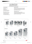
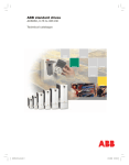
ABB component drives
ACS100, 0.12 to 2.2 kW
ABB general machinery drives
ACS140, 0.12 to 2.2 kW
ABB decentralized drives
ACS160, 0.55 to 2.2 kW
Technical Catalogue
BUSINESS
PROFILE
INDUSTRIES
PRODUCTS
APPLICATIONS
EXPERTISE
PARTNERS
SERVICES
11948_ACS_100_160_Rev_E.p65
1
5/30/2005, 1:25 PM
Products
Features and selection guide
Application macros
ABB component drives, ACS100
........................................................................................................... 4
.............................................................................................. 5
Technical specification
........................................................................................................... 6
Technical data
........................................................................................................... 7
Connection examples
........................................................................................................... 8
Options
........................................................................................................... 9 - 11
ABB general machinery drives, ACS140
.............................................................................................. 12
Technical specification
........................................................................................................... 13
Technical data
........................................................................................................... 14
Connection examples
........................................................................................................... 15
Options
........................................................................................................... 16 - 18
Brake options
.............................................................................................. 19
Brake units and choppers
ABB decentralized drives, ACS160
........................................................................................................... 19
.............................................................................................. 20
Technical specification
........................................................................................................... 21
Technical data
........................................................................................................... 22
Connection examples
........................................................................................................... 22
Electro magnetic compatibility
........................................................................................................... 23
Options
........................................................................................................... 24 - 25
Start-up and maintenance tool
DriveWindow Light 2
Contact and web information
2
.............................................................................................. 3
.............................................................................................. 26
........................................................................................................... 26
.............................................................................................. 27
3AFE 64564102 REV E EN 30.5.2005
11948_ACS_100_160_Rev_E_a.p65
2
5/30/2005, 1:20 PM
Features and selection guide
200-240 V
0.12-2.2 kW
200-480 V
0.12-2.2 kW
380-480 V
0.55-2.2 kW
ACS100
ACS140
ACS160
0.1 … 1800
0.1 … 1800
0.1 … 1800
0.1 … 1800
0.1 … 1800
Functions
Start; normal/flying/torque boost
Start; premagnetising
IR compensation
Stop; ramp/coasting
Stop; DC brake
DC hold
U/f -ratio; linear/square
Acceleration/deceleration 1 (s)
Acceleration/deceleration 2 (s)
S-ramp; fast/medium/slow
Preset speeds1)
Critical frequencies1)
Slip compensation
1
7
2
7
2
1
3
3
Application macros
Factory
ABB Standard
3-wire
Alternate
Motor potentiometer
Hand/Auto Control
PID Control (process)
Premagnetise
Pump and Fan Control (PFC)
Positioning
Protection, fault functions
Overload protection
Stall protection
Output overcurrent
Output short circuit
Ground fault, motor cable
Underload
Network failure
Low input signal level (AI<min)
Panel fault
Overvoltage
Undervoltage
External fault
Automatic fault reset, undervoltage
Automatic fault reset, overvoltage, overcurrent, AI<min
Fault history1)
Supervision functions (programmable) 2)
Speed
Current
Torque
Output power
Reference setpoint
1)
2)
The number indicates the amount of different speeds / frequencies / faults.
Many other signals can also be monitored, see the user's manual.
standard feature
3AFE 64564102 REV E EN 30.5.2005
11948_ACS_100_160_Rev_E_a.p65
3
5/30/2005, 1:20 PM
3
Application macros
What are application macros?
A wide selection of pre-set application macros have
been created to ensure fast and easy commissioning
of all ABB low voltage AC drives.
With application macros you can set up your drive
extremely fast for all the most common applications.
And of course you can fine tune the drive operation
by changing the pre-set parameters if needed.
The Factory application macro is intended for
applications where the drive is used without a control
panel, providing a general purpose I/O-configuration.
By changing only one parameter all the drive’s
macro-specific parameters are automatically set with
new pre-set values. The drive’s I/O-terminals are also
automatically configured to meet the demands set by
your application.
All the application macros which can be used with
ACS100, ACS140 and ACS160 drives are listed below
together with explanations.
ACS100
ACS140
The ABB Standard (typically used in Europe) and
the 3-wire (typically used in the United States)
application macros are configured for general purpose
applications, and offer two additional pre-set speeds
compared to the factory application macro.
The Alternate application macro has an I/Oconfiguration adopted to a sequence of DI-control
signals used when alternating the direction of the
drive.
The Motor Potentiometer application macro provides
a cost-effective interface for PLCs that vary the speed
of the drive using only digital signals.
The Hand/Auto application macro offers an I/Oconfiguration typically used in HVAC applications.
The PID Control application macro is intended for
use with closed-loop control systems such as pressure
and flow control.
The Premagnetise application macro enables rapid
starting by eliminating the delay normally experienced
while flux builds up in the motor.
The Positioning application macro is for simple
positioning tasks. Default operation is appropriate for
example for conveyer systems where items are moved
a certain distance.
4
3AFE 64564102 REV E EN 30.5.2005
11948_ACS_100_160_Rev_E_a.p65
4
5/30/2005, 1:20 PM
ACS160
ABB component drives, ACS100
0.12 kW - 2.2 kW supply voltage 200 - 240 V
Unique features
Mounting options
• The plug and produce construction
• Easy and simple to use
• Many installation possibilities
In addition to the conventional wall mounting and
time-saving DIN rail mounting, the ACS100 also offers
flange-mounting. The heatsink is located outside the
enclosure and hence the major share of the power loss
is external to the enclosure.
More value for money
• Parameter copy
• Wide range of protection
• Fast and accurate control
• Fast and accurate I/O response
• Cost optimization without the panel
Heatsinkless
In cases where space is a limitation, drives without a
heatsink can be delivered as standard. The user has to
provide an installation surface with sufficient cooling.
For more information, please refer to the ACS100
User's Manual.
Mounting options
wall mounting
heatsinkless
mounting on DIN rail
flange mounting
146 mm
146 mm
146 mm
218 mm
245 mm
Dimensions
176 mm
80 mm
80 mm
frame size H
frame size A
169 mm
186 mm
149 mm
119 mm
80 mm
frame size B
80 mm
80 mm
frame size C
frame size D
3AFE 64564102 REV E EN 30.5.2005
11948_ACS_100_160_Rev_E_a.p65
5
5/30/2005, 1:20 PM
5
ACS100 technical specification
Mains connection
Power range: 0.12 - 2.2 kW
Voltage: 1-phase and 3-phase, 200 to 240 V, ±10%
Frequency: 48 to 63 Hz
Power Factor: 0.98
Use 60°C rated power cable (75°C if Tamb above 45°C).
Max. wire sizes (mm2)
• 4 single core/torque 0.8 Nm
Serial communication for the control panel:
Modbus protocol
Protection limits
Motor connection
Overvoltage
• Running V DC:
• Start inhibit V DC:
Undervoltage
• Running V DC:
• Start inhibit V DC:
Voltage: 3-phase, from 0 to USUPPLY
Frequency: 0 to 300 Hz
Environmental limits
Continuous loading capability (constant torque at a max.
ambient temperature of 40°C): Rated output current I2N.
Overload capacity (at a max. ambient temp. of 40°C):
• at constant torque 1.5 x I2N, for 1 minute every
10 minutes
• at constant torque 1.25 x I2N, for 2 minutes every
10 minutes
Characteristic data for short-time, intermittent and
periodic load cycles are available on request.
Switching frequency:
Standard 4 kHz, Low-noise 8 kHz, Silent 16 kHz
Acceleration time: 0.1 to 1800 s
Deceleration time: 0.1 to 1800 s
For max. motor cable lengths see p. 11.
Programmable control connections
Max. wire sizes (mm2)
• 0.5-1.5 (AWG 22...AWG 16)/torque 0.4 Nm
One analog input:
• Voltage signal: 0 (2) to 10 V, 200 kΩ single-ended
• Current signal: 0 (4) to 20 mA, 500 Ω single-ended
• Potentiometer reference value:
10 V ±2% max. 10 mA, 1 kΩ ≤ R ≤ 10 kΩ
• Response time:
≤60 ms
• Resolution:
0.1%
• Accuracy:
±1%
Auxiliary voltage: 12 V DC, max. 100 mA
Three digital inputs:
• 12 V DC with internal or 12 V ... 24 V DC with external
supply, PNP and NPN
• Input impedance: 1.5 kΩ
• Response time:
≤ 9 ms
420 (corr. to 295 V input)
390 (corr. to 276 V input)
200 (corr. to 142 V input)
230 (corr. to 162 V input)
Ambient temperatures:
• Output current = I2, fswitch = 4 kHz: 0 to 40°C
• Output current = 0.8 · I2, fswitch = 4 kHz: 40 to 50°C
• Output current = I2, fswitch = 8 kHz: 0 to 30°C
• Output current = 0.9 · I2, fswitch = 8 kHz: 30 to 40°C
• Output current = 0.75 · I2, fswitch = 16 kHz: 0 to 30°C
Altitude:
• Output current = I2: 0 to 1000 m
• Output current reduced by 1% per 100 m over 1000 m
to 2000 m
Relative humidity: lower than 95%
(without condensation)
Protection class: IP 20
Paint colour: NCS 1502-Y, RAL 9002, PMS 420 C
Contamination levels: no conductive dust, corrosive liquids
or gases (IEC 721-3-3).
Product compliance
•
•
•
•
Low Voltage Directive 73/23/EEC with supplements
EMC Directive 89/336/EEC with supplements
Quality assurance system ISO 9001 and ISO 14001
CE, UL, ULc and C-Tick approvals
Options
• Control panel
• Extension cable 3 m with IP 65 Kit for control panels
PEC-98-0008
• EMC IP 20 input filters
• Brake units and choppers
• Input and output chokes
• NEMA 1/ IP 21 Installation kits
One fault relay:
• Switching voltage: 12 to 250 V AC or max 30 V DC/0.5 A
• Maximum continuous current: 10 mA to 2 A
6
3AFE 64564102 REV E EN 30.5.2005
11948_ACS_100_160_Rev_E_a.p65
6
5/30/2005, 1:20 PM
ACS100 technical data
Nominal ratings
OverNominal Frame
Input
Output
Max.
Over- temp. Line
Type code
motor
size/
current current output
current (heat fuse1)
P N 2)
weight
I 1N
I 2N
current
(peak) sink)
oC
kW
kg
A
A
A
A
A
With heatsink, 1-phase supply voltage 200 - 240 V ±10%, 0.12 - 2.2 kW
ACS101-K18-1
0.12
A/0.9
2.7
1.0
1.5
3.2
90
6
ACS101-K25-1
0.18
A/0.9
4.4
1.4
2.1
4.5
90
6
ACS101-K37-1
0.25
A/0.9
5.4
1.7
2.6
5.5
90
10
ACS101-K75-1
0.37
A/0.9
6.9
2.2
3.3
7.1
90
10
ACS101-1K1-1
0.55
A/0.9
9.0
3.0
4.5
9.7
90
10
ACS101-1K6-1
0.75
B/1.2
10.8
4.3
6.5
13.8
90
16
ACS101-2K1-1
1.1
C/1.6
14.8
5.9
8.9
19.0
95
16
ACS101-2K7-1
1.5
C/1.6
18.2
7.0
10.5
23.5
95
20
ACS101-4K1-1
2.2
D/1.9
22.0
9.0
13.5
34.5
95
25
Heatsinkless, 1-phase supply voltage 200 - 240 V ±10%, 0.12 - 2.2 kW
ACS101-H18-1
0.12
H/0.8
2.7
1.0
1.5
3.2
90
6
ACS101-H25-1
0.18
H/0.8
4.4
1.4
2.1
4.5
90
6
ACS101-H37-1
0.25
H/0.8
5.4
1.7
2.6
5.5
90
10
ACS101-H75-1
0.37
H/0.8
6.9
2.2
3.3
7.1
90
10
ACS101-1H1-1
0.55
H/0.8
9.0
3.0
4.5
9.7
90
10
ACS101-1H6-1
0.75
H/0.8
10.8
4.3
6.5
13.8
90
16
With heatsink, 3-phase supply voltage 200 - 240 V ±10%, 0.12 - 2.2 kW
ACS103-K75-1
0.37
A/0.8
3.2
2.2
3.3
7.1
90
6
ACS103-1K1-1
0.55
A/0.8
4.2
3.0
4.5
9.7
90
6
ACS103-1K6-1
0.75
B/1.1
5.3
4.3
6.5
13.8
90
6
ACS103-2K1-1
1.1
C/1.5
7.2
5.9
8.9
19.0
90
10
ACS103-2K7-1
1.5
C/1.5
8.9
7.0
10.5
23.5
95
10
ACS103-4K1-1
2.2
D/1.8
12.0
9.0
13.5
34.5
95
16
1)
2)
Power losses
Power Control
circuit circuit
W
W
7
10
12
13
19
27
39
48
70
8
10
12
14
16
17
18
19
20
7
10
12
13
19
27
8
10
12
14
16
17
13
19
27
39
48
70
14
16
17
18
19
20
Fuse type: UL class CC or T. For non-UL installations IEC269 gG.
PN rated motor power. The power ratings in kW apply to most 2- and 4-pole IEC 34 motors.
The current ratings are the same regardless of supply voltages. The rated current of the ACS100 drive
must be higher than or equal to the rated motor current to achieve the rated motor power given in the table.
3AFE 64564102 REV E EN 30.5.2005
11948_ACS_100_160_Rev_E_a.p65
7
5/30/2005, 1:20 PM
7
ACS100 connection examples
These connections are shown as examples only.
Please refer to the ACS100 User's Manual for more
detailed information.
ACS100
DI configuration
ABB standard
jogging
reversal
start/
stop
NPN connected
X1
1
2
3
4
5
6
7
8
9
10
11
12
13
14
15
SCR
Al
AGND
10 V
All
AGND
AGND
12 V
DCOM
Dl 1
Dl 2
Dl 3
RO 1
RO 2
RO 3
ACS100
DI configuration
3-wire
reversal
stop start
NPN connected
Frequency reference value
from an external current
source
SCR
Al
AGND
10 V
All
AGND
AGND
12 V
DCOM
Dl 1
Dl 2
Dl 3
RO 1
RO 2
RO 3
ACS100
0...20 mA
SCR
8
X1
1
2
3
4
5
6
7
8
9
10
11
12
13
14
15
1
2
3
4
5
6
SCR
Al
AGND
10 V
All
AGND
3AFE 64564102 REV E EN 30.5.2005
11948_ACS_100_160_Rev_E_a.p65
8
5/30/2005, 1:20 PM
ACS100 options
control
modes
fault
indicator
units
shaft
direction
display
modes
start/stop
menu
direction
enter
up/down
Control panel
Type code: ACS100 - PAN
ACS100 drives can be bought with or without a
detachable control panel. If you prefer to buy the
drive without the control panel we still offer you a
chance to have the panel as an option. Using the
control panel, parameters can be exchanged between
two ACS100 drives. This is called parameter upload/
download procedure.
mounting plate or door
mounting screws
with sleeve
clamp for cable
Panel extension cable kit
Type code: PEC-98-0008
This option includes a gasket, a 3 m connection cable
for control panels, fixing material for the cables and a
drilling jig. With this kit IP 65 protection class is
achieved.
gasket
cable hole
control panel
plastic clamp with tape
3AFE 64564102 REV E EN 30.5.2005
11948_ACS_100_160_Rev_E_a.p65
9
5/30/2005, 1:20 PM
9
ACS100 options
EMC filters
Instructions to comply with EN61800-3:
To comply with:
• 1st Environment, unrestricted distribution, please
contact your ABB distributor.
• 1st Environment, restricted distribution, always
use optional RFI filter as specified in the table
below.
To comply with:
• 2nd Environment, unrestricted distribution,
always use optional RFI filter as specified in the
table below
• 2nd Environment, restricted distribution, always
use optional RFI filter as specified in the table
below. If RFI filters are to be avoided, an EMC plan
has to be created between the customer and the
sales person.
1-phase supply voltage 200 - 240 V, 0.12 - 2.2 kW
Type code
ACS101-K18-1, -H18-1
ACS101-K25-1, -H25-1
ACS101-K37-1, -H37-1
ACS101-K75-1, -H75-1
ACS101-1K1-1, -1H1-1
ACS101-1K6-1, -1H6-1
ACS101-2K1-1
ACS101-2K7-1
ACS101-4K1-1
Filter type
ACS100/140-IFAB-1
ACS100/140-IFAB-1
ACS100/140-IFAB-1
ACS100/140-IFAB-1
ACS100/140-IFAB-1
ACS100/140-IFAB-1
ACS100/140-IFCD-1
ACS100/140-IFCD-1
ACS100/140-IFCD-1
Max. motor cable length m
Switching frequency
1st environment
2nd environment
4 kHz 8 kHz 16 kHz 4 kHz 8 kHz 16 kHz
30
20
10
50
50
10
30
20
10
50
50
10
30
20
10
50
50
10
30
20
10
75
75
10
30
20
10
75
75
10
30
20
10
75
75
10
30
20
10
75
75
10
30
20
10
75
75
10
30
20
10
75
75
10
Dimensions
A
mm
81
81
81
81
81
81
81
81
81
RFI filter type code ACS100 -FLT-C allows you to use longer motor cables.
Please contact your ABB distributor. IFAB, IFCD and FLT-C filters with protection class IP 20.
Note! With types ACS...H mount the filter next to the drive.
3-phase supply voltage 200 - 240 V,
0.37 - 2.2 kW
Use EMC filter type ACS140-FLT-C with all
ACS103-xKx-1 converter types. Maximum motor
cable length is 100 m in 1st Environment, restricted
distribution with 4 kHz and 8 kHz switching
frequency. For ACS103-4K1-1 with EMC filter the
maximum continuous load is 70% of nominal.
NEMA 1/ IP 21 installation kit
Type code: NEMA 1/ IP 21
With this installation kit NEMA 1/ IP 21 protection
class is achieved for ACS100 and for the EMC filter,
if the filter is attached directly to the drive.
10
3AFE 64564102 REV E EN 30.5.2005
11948_ACS_100_160_Rev_E_a.p65
10
5/30/2005, 1:20 PM
B
mm
186
186
186
186
186
186
286
286
286
C
mm
191
191
191
191
191
228
211
211
218
D
mm
42
42
42
42
42
42
42
42
42
ACS100 options
Input and output chokes
Output chokes are used when motor cables above
normal length are required. This is possible because
the output choke reduces capacitive currents and
voltage reflections. The maximum switching frequency
with output chokes is 4 kHz. Please note also your
local EMC regulations.
Type code
1-phase supply
ACS101-K18-1
ACS101-K25-1
ACS101-K37-1
ACS101-K75-1
ACS101-1K1-1
ACS101-1K6-1
ACS101-2K1-1
ACS101-2K7-1
ACS101-4K1-1
3-phase supply
ACS103-K75-1
ACS103-1K1-1
ACS103-1K6-1
ACS103-2K1-1
ACS103-2K7-1
ACS103-4K1-1
1-phase supply
ACS101-H18-1
ACS101-H25-1
ACS101-H37-1
ACS101-H75-1
ACS101-1H1-1
ACS101-1H6-1
1)
Optional input chokes can be used with the ACS100 in
case voltage fluctuation problems occur in the supply
net. The chokes eliminate converter trips caused by
overvoltage spikes. At the same time chokes reduce
line harmonics and therefore help to prevent other
sensitive equipment in the same net from tripping.
Choke type
Input choke
Output choke
voltage 200 SACL21
SACL21
SACL21
SACL21
SACL21
SACL22
SACL22
SACL23
SACL24
voltage 200 ACS-CHK-B3
ACS-CHK-B3
ACS-CHK-B3
ACS-CHK-B3
ACS-CHK-C3
ACS-CHK-C3
voltage 200 SACL21
SACL21
SACL21
SACL21
SACL21
SACL21
Max. motor cable length
with choke1) without choke1)
m
m
240 V, 0.12 - 2.2 kW
ACS-CHK-B3
75
50
ACS-CHK-B3
75
50
ACS-CHK-B3
75
50
ACS-CHK-B3
110
75
ACS-CHK-B3
110
75
ACS-CHK-B3
110
75
ACS-CHK-C3
110
75
ACS-CHK-C3
110
75
ACS-CHK-C3
110
75
240 V, 0.37 - 2.2 kW
ACS-CHK-B3
110
75
ACS-CHK-B3
110
75
ACS-CHK-B3
110
75
ACS-CHK-C3
110
75
ACS-CHK-C3
110
75
ACS-CHK-C3
110
75
240 V, 0.12 - 0.75 kW / heatsinkless
ACS-CHK-B3
75
50
ACS-CHK-B3
75
50
ACS-CHK-B3
75
50
ACS-CHK-B3
110
75
ACS-CHK-C3
110
75
ACS-CHK-C3
110
75
Without EMC filter
Technical data
Choke type
ACS-CHK-B3
ACS-CHK-C3
SACL21
SACL22
SACL23
SACL24
L/mH
Dimensions
HxWxD
mm
300x102x112
300x102x112
76x63x62
92x76x63
92x76x63
92x76x63
1.5
0.8
3.2
1.5
0.7
0.7
Weight
kg
Max. cable
mm 2
I/A
4.0
4.0
1.0
1.3
1.3
1.9
4
4
4
10
10
6
8.0
14.0
8.5
15
22
28
Brake options
The ACS100 can be equipped with a brake unit.
For more information please refer to page 19 for the
ACS100 brake options.
3AFE 64564102 REV E EN 30.5.2005
11948_ACS_100_160_Rev_E_a.p65
11
5/30/2005, 1:20 PM
11
ABB general machinery drives, ACS140
0.12 kW - 2.2 kW supply voltage 200 - 480 V
Unique features
Mounting options
• Fast and extensive I/O
• PID control
• Application macros
• Many installation possibilities
• 200 - 480 V, 1-phase or 3-phase
In addition to the conventional wall mounting and
time-saving DIN rail mounting, ACS140 also offers
flange-mounting. The heatsink is located outside the
enclosure and hence the major share of the power loss
is external to the enclosure.
More value for money
Heatsinkless series
• Possibility to have IP 21 enclosure
• Very fast and accurate control
• Extremely good repeatability
• Cost optimization without the panel
In cases where space is a limitation, drives without a
heatsink can be delivered as standard. The user has to
provide an installation surface with sufficient cooling.
For more information, please refer to the ACS140
User’s Manual.
Mounting options
wall mounting
heatsinkless
mounting on DIN rail
flange mounting
146 mm
146 mm
146 mm
218 mm
245 mm
Dimensions
176 mm
80 mm
80 mm
frame size H
12
frame size A
169 mm
186 mm
149 mm
119 mm
80 mm
frame size B
80 mm
frame size C
3AFE 64564102 REV E EN 30.5.2005
11948_ACS_100_160_Rev_E_a.p65
12
5/30/2005, 1:20 PM
80 mm
frame size D
ACS140 technical specification
Mains connection
Power range: 0.12 - 2.2 kW
Voltage: 1-phase and 3-phase, 200 to 240 V, ±10%
3-phase, 380 to 480 V, ±10%
Frequency: 48 to 63 Hz
Power Factor: 0.98
Use 60°C rated power cable (75°C if Tamb above 45°C).
Max. wire sizes (mm2)
• 4 single core/torque 0.8 Nm
Motor connection
Voltage: 3-phase, from 0 to USUPPLY
Frequency: 0 to 300 Hz
Continuous loading capability (constant torque at a max.
ambient temperature of 40°C): Rated output current I2N.
Overload capacity (at a max. ambient temp. of 40°C):
• at constant torque 1.5 x I2N, for 1 minute every
10 minutes
• at constant torque 1.25 x I2N, for 2 minutes every
10 minutes
Characteristic data for short-time, intermittent and
periodic load cycles are available on request.
Switching frequency:
Standard 4 kHz, Low-noise 8 kHz, Silent 16 kHz
Acceleration time: 0.1 to 1800 s
Deceleration time: 0.1 to 1800 s
Serial communication for the control panel or external
control: Modbus protocol
Protection limits
Overvoltage, 200 to 240 V units
• Running V DC:
420 (corr. to 295
• Start inhibit V DC: 390 (corr. to 276
Overvoltage, 380 to 480 V units
• Running V DC:
842 (corr. to 595
• Start inhibit V DC: 661 (corr. to 380
765 (corr. to 440
Undervoltage, 200 to 240 V units
• Running V DC:
200 (corr. to 142
• Start inhibit V DC: 230 (corr. to 162
Undervoltage, 380 to 480 V units
• Running V DC:
333 (corr. to 247
• Start inhibit V DC: 436 (corr. to 380
505 (corr. to 440
V input)
V input)
V input)
- 415 V input)
- 480 V input)
V input)
V input)
V input)
- 415 V input)
- 480 V input)
Environmental limits
Ambient temperatures:
• Output current = I2, fswitch = 4 kHz: 0 to 40°C
• Output current = 0.8 · I2, fswitch = 4 kHz: 40 to 50°C
• Output current = I2, fswitch = 8 kHz: 0 to 30°C
• Output current = 0.9 · I2, fswitch = 8 kHz: 30 to 40°C
• Output current = 0.75 · I2, fswitch = 16 kHz: 0 to 30°C 1)
Altitude:
• Output current = I2: 0 to 1000 m
• Output current reduced by 1% per 100 m over 1000 m
to 2000 m
For max. motor cable lengths see p. 18.
Relative humidity: lower than 95% (without condensation)
Programmable control connections
Max. wire sizes (mm2)
• 0.5-1.5 (AWG 22...AWG 16)/torque 0.4 Nm
Two analog inputs:
• Voltage signal: 0 (2) to 10 V, 200 kΩ single-ended
• Current signal: 0 (4) to 20 mA, 500 Ω single-ended
• Potentiometer reference value:
10 V ±2% max. 10 mA, 1 kΩ ≤ R ≤ 10 kΩ
• Response time:
≤ 60 ms
• Resolution:
0.1%
• Accuracy:
±1%
Protection class: IP 20
Paint colour: NCS 1502-Y, RAL 9002, PMS 420 C
Contamination levels: no conductive dust, corrosive liquids
or gases (IEC 721-3-3).
Product compliance
•
•
•
•
Low Voltage Directive 73/23/EEC with supplements
EMC Directive 89/336/EEC with supplements
Quality assurance system ISO 9001 and ISO 14001
CE, UL, ULc and C-Tick approvals
One analog output: 0 (4) to 20 mA, load <500 Ω
Options
Auxiliary voltage: 12 V DC, max. 100 mA
Five digital inputs:
• 12 V… 24 V DC with internal or external supply,
PNP and NPN
• Input impedance: 1.5 kΩ
• Response time:
≤ 9 ms
Two relay outputs:
• Switching voltage: 12 to 250 V AC or max 30 V
DC/0.5 A
• Maximum continuous current: 10 mA to 2 A
•
•
•
•
•
•
•
•
•
1)
Control panel
RS 485/232 adapter
DriveWindow Light 2
Extension cable 3 m with IP 65 Kit for control panels
PEC-98-0008
EMC IP 20 input filters
Brake units and choppers
Input and output chokes
NEMA 1/ IP 21 Installation kits
Fieldbus modules
Except ACS143-1K1-3 and ACS143-2K1-3 where
output current = 0.55 x I2 , fSWITCH =16 kHz: 0 to 30°C.
3AFE 64564102 REV E EN 30.5.2005
11948_ACS_100_160_Rev_E_a.p65
13
5/30/2005, 1:20 PM
13
ACS140 technical data
Nominal ratings
Nominal Frame
Input
Output Max.
OverType code
motor
size/
current current output
current
P N 2)
weight
I 1N
I 2N
current
(peak)
kW
kg
A
A
A
A
With heatsink, 1-phase supply voltage 200 - 240 V ±10%, 0.12 - 2.2 kW
ACS141-K18-1
0.12
A/0.9
2.7
1.0
1.5
3.2
ACS141-K25-1
0.18
A/0.9
4.4
1.4
2.1
4.5
ACS141-K37-1
0.25
A/0.9
5.4
1.7
2.6
5.5
ACS141-K75-1
0.37
A/0.9
6.9
2.2
3.3
7.1
ACS141-1K1-1
0.55
A/0.9
9.0
3.0
4.5
9.7
ACS141-1K6-1
0.75
B/1.2
10.8
4.3
6.5
13.8
ACS141-2K1-1
1.1
C/1.6
14.8
5.9
8.9
19.0
ACS141-2K7-1
1.5
C/1.6
18.2
7.0
10.5
23.5
ACS141-4K1-1
2.2
D/1.9
22.0
9.0
13.5
34.5
Heatsinkless, 1-phase supply voltage 200 - 240 V ±10%, 0.12 - 2.2 kW
ACS141-H18-1
0.12
H/0.8
2.7
1.0
1.5
3.2
ACS141-H25-1
0.18
H/0.8
4.4
1.4
2.1
4.5
ACS141-H37-1
0.25
H/0.8
5.4
1.7
2.6
5.5
ACS141-H75-1
0.37
H/0.8
6.9
2.2
3.3
7.1
ACS141-1H1-1
0.55
H/0.8
9.0
3.0
4.5
9.7
ACS141-1H6-1
0.75
H/0.8
10.8
4.3
6.5
13.8
With heatsink, 3-phase supply voltage 200 - 240 V ±10%, 0.12 - 2.2 kW
ACS143-K75-1
0.37
A/0.8
3.2
2.2
3.3
7.1
ACS143-1K1-1
0.55
A/0.8
4.2
3.0
4.5
9.7
ACS143-1K6-1
0.75
B/1.1
5.3
4.3
6.5
13.8
ACS143-2K1-1
1.1
C/1.5
7.2
5.9
8.9
19.0
ACS143-2K7-1
1.5
C/1.5
8.9
7.0
10.5
23.5
ACS143-4K1-1
2.2
D/1.8
12.0
9.0
13.5
34.5
With heatsink, 3-phase supply voltage 380 - 480 V ±10%, 0.37 - 2.2 kW
ACS143-K75-3
0.37
A/0.8
2.0
1.2
1.8
4.2
ACS143-1K1-3
0.55
A/0.8
2.8
1.7
2.6
5.6
ACS143-1K6-3
0.75
B/1.1
3.6
2.0
3.0
6.6
ACS143-2K1-3
1.1
C/1.1
4.8
2.8
4.2
9.2
ACS143-2K7-3
1.5
C/1.5
5.8
3.6
5.4
11.9
ACS143-4K1-3
2.2
D/1.8
7.9
4.9
7.4
16.3
Heatsinkless, 3-phase supply voltage 380 - 480 V ±10%, 0.37 - 2.2 kW
ACS143-H75-3
0.37
H/0.8
2.0
1.2
1.8
4.2
ACS143-1H1-3
0.55
H/0.8
2.8
1.7
2.6
5.6
ACS143-1H6-3
0.75
H/0.8
3.6
2.0
3.0
6.6
ACS143-2H1-3
1.1
H/0.8
4.8
2.8
4.2
9.2
1)
2)
14
Overtemp. Line
(heat fuse1)
sink)
oC
A
Power losses
Power Control
circuit
circuit
W
W
90
90
90
90
90
90
95
95
95
6
6
10
10
10
16
16
20
25
7
10
12
13
19
27
39
48
70
8
10
12
14
16
17
18
19
20
90
90
90
90
90
90
6
6
10
10
10
16
7
10
12
13
19
27
8
10
12
14
16
17
90
90
90
90
95
95
6
6
6
10
10
16
13
19
27
39
48
70
14
16
17
18
19
20
90
90
90
90
95
95
6
6
6
6
10
10
14
20
27
39
48
70
14
16
17
18
19
20
90
90
90
90
6
6
6
6
14
20
27
39
14
16
17
18
Fuse type: UL class CC or T. For non-UL installations IEC269 gG.
PN rated motor power. The power ratings in kW apply to most 2- and 4-pole IEC 34 motors.
The current ratings are the same regardless of supply voltages. The rated current of the ACS140
drive must be higher than or equal to the rated motor current to achieve the rated motor
power given in the table.
3AFE 64564102 REV E EN 30.5.2005
11948_ACS_100_160_Rev_E_a.p65
14
5/30/2005, 1:20 PM
ACS140 connection examples
These connections are shown as an example only.
Please refer to the ACS140 User's Manual for more
detailed information.
ACS140
DI configuration
default (0)
*)
jogging
reversal
start/
stop
NPN connected
X1
1
2
3
4
5
6
7
8
9
10
11
12
13
14
15
16
17
18
19
SCR
Al 1
AGND
10 V
Al 2
AGND
AO
AGND
12 V
DCOM
Dl 1
Dl 2
Dl 3
Dl 4
Dl 5
RO 1A
RO 1B
RO 2A
RO 2B
S1:1:U
S1:2:
ACS140
DI configuration
default (1)
*)
reversal
stop start
NPN connected
Frequency reference value
from an external current
source
X1
1
2
3
4
5
6
7
8
9
10
11
12
13
14
15
16
17
18
19
SCR
Al 1
AGND
10 V
Al 2
AGND
AO
AGND
12 V
DCOM
Dl 1
Dl 2
Dl 3
Dl 4
Dl 5
RO 1A
RO 1B
RO 2A
RO 2B
S1:1:U
S1:2:
ACS140
0...20 mA
SCR
X1
1
2
3
4
5
6
S1:1:I
S1:2:
SCR
Al 1
AGND
10 V
Al 2
AGND
*) If external voltages are used open
the jumper X1: 9,10.
Use the DCOM and digital inputs.
3AFE 64564102 REV E EN 30.5.2005
11948_ACS_100_160_Rev_E_a.p65
15
5/30/2005, 1:20 PM
15
ACS140 options
RS 485/232 adapter
Type code: ACS140 RS 485/232
If you want to control the ACS140 drive via Modbus
or use the DriveWindow Light 2 software you need
to replace the panel with the RS 485/232 adapter.
When the adapter is used, several ACS140 units can
be controlled using Modbus protocol. The modbus
communication also creates the base for controlling
the drive via other gateways.
RS 485 terminal X2
Control panel
control
modes
fault
indicator
units
display
modes
shaft
direction
start/stop
menu
direction
enter
up/down
Type code: ACS100 - PAN
ACS140 drives can be bought
with or without a detachable
control panel. If you prefer to
buy the drive without the
control panel we still offer
you a chance to have the
panel as an option. Using the
control panel, parameters can
be exchanged between two
ACS140 drives. This is called
parameter upload/download
procedure.
Panel extension cable kit
Type code: PEC-98-0008
This option includes a gasket, a 3 m connection cable
for control panels, fixing material for the cables and a
drilling jig. With this kit IP 65 protection class is
achieved.
mounting plate or door
1 (B)
ACS140 with RS
485/232 adapter
communication
speed setting
DIP-switch S1
RS 232
terminal X4
ABC fieldbus modules
Type codes: ABC-PDP and ABC-DEV
Up to ten drives can be controlled with one ABC
fieldbus module. The drives may be of type
ACS140 and/or ACS160. ABC modules are
available for Profibus (type code ABC-PDP) and
DeviceNet (type code ABC-DEV) fieldbus
protocols. The module is DIN rail mountable with
protection class IP 20. The ABC module requires
24 V DC power supply and provides an RS 485
Modbus interface for communication with the
drives. The response time on the Modbus
network is approximately 200 ms per drive.
clamp for cable
cable hole
3AFE 64564102 REV E EN 30.5.2005
16
RS 232/RS 485
mode select
jumper S5
RS 485 terminal X3
plastic clamp with tape
11948_ACS_100_160_Rev_E_a.p65
1 (B)
2 (C)
control panel
16
2 (C)
3 (A)
mounting screws
with sleeve
gasket
3 (A)
RS 485 bus
termination
jumpers S2
and S3
LEDs:
RxD
TxD
power
5/30/2005, 1:20 PM
ACS140 options
EMC filters
Instructions to comply with EN61800-3:
To comply with:
• 1st Environment, unrestricted distribution, please
contact your ABB distributor.
• 1st Environment, restricted distribution, always
use optional RFI filter as specified in the table
below.
To comply with:
• 2nd Environment, unrestricted distribution, always
use optional RFI filter as specified in the table below.
• 2nd Environment, restricted distribution, always use
optional RFI filter as specified in the table below. If
RFI filters are to be avoided, an EMC plan has to be
created between the customer and the sales person.
1-phase supply voltage 200 - 240 V, 0.12 - 2.2 kW
Type code
ACS141-K18-1, -H18-1
ACS141-K25-1, -H25-1
ACS141-K37-1, -H37-1
ACS141-K75-1, -H75-1
ACS141-1K1-1, -1H1-1
ACS141-1K6-1, -1H6-1
ACS141-2K1-1
ACS141-2K7-1
ACS141-4K1-1
Filter type
ACS100/140-IFAB-1
ACS100/140-IFAB-1
ACS100/140-IFAB-1
ACS100/140-IFAB-1
ACS100/140-IFAB-1
ACS100/140-IFAB-1
ACS100/140-IFCD-1
ACS100/140-IFCD-1
ACS100/140-IFCD-1
Max. motor cable length m
Switching frequency
2nd environment
1st environment
4 kHz 8 kHz 16 kHz 4 kHz 8 kHz 16 kHz
30
20
10
50
50
10
30
20
10
50
50
10
30
20
10
50
50
10
30
20
10
75
75
10
30
20
10
75
75
10
30
20
10
75
75
10
30
20
10
75
75
10
30
20
10
75
75
10
30
20
10
75
75
10
Dimensions
A
mm
81
81
81
81
81
81
81
81
81
B
mm
186
186
186
186
186
186
286
286
286
C
mm
191
191
191
191
191
228
211
211
218
D
mm
42
42
42
42
42
42
42
42
42
3-phase supply voltage 380 - 480 V, 0.37 - 2.2 kW
Type code
Filter type
ACS143-K75-3, -H75-3
ACS143-1K1-3, -1H1-3
ACS143-1K6-3, -1H6-3
ACS143-2K1-3, -2H1-3
ACS143-2K7-3
ACS143-4K1-3
ACS140-IFAB-3
ACS140-IFAB-3
ACS140-IFAB-3
ACS140-IFAB-3
ACS140-IFCD-3
ACS140-IFCD-3
Max. motor cable length m
Switching frequency
1st environment
2nd environment
4 kHz 8 kHz 16 kHz 4 kHz 8 kHz 16 kHz
30
20
10
30
30
10
30
20
10
50
50
10
30
20
10
50
50
10
30
20
10
50
50
10
30
20
10
50
50
10
30
20
10
50
50
10
Dimensions
A
mm
81
81
81
81
81
81
B
mm
186
186
186
286
286
286
C
mm
191
191
228
211
211
218
D
mm
42
42
42
42
42
42
RFI filter type code ACS100 -FLT-C allows you to use longer motor cables. Please contact
your ABB distributor. IFAB, IFCD and FLT-C filters with protection class IP 20.
Note! With types ACS...H mount the filter next to the drive.
3-phase supply voltage 200 - 240 V,
0.37 - 2.2 kW
Use EMC filter type ACS140-FLT-C with all
ACS143-xKx-1 converter types. Maximum motor cable
length is 100 m in 1st Environment, restricted
distribution, with 4 kHz and 8 kHz switching
frequency. For ACS143-4K1-1 with EMC filter the
maximum continuous load is 70% of nominal.
NEMA 1/ IP 21 installation kit
Type code: NEMA 1/ IP 21
With this installation kit NEMA 1/ IP 21 protection class
is achieved for ACS140 and for the EMC filter, if the
filter is attached directly to the drive.
3AFE 64564102 REV E EN 30.5.2005
11948_ACS_100_160_Rev_E_a.p65
17
5/30/2005, 1:20 PM
17
ACS140 options
Input and output chokes
Output chokes are used when motor cables above
normal length are required. The cable can be roughly
1.5 times the standard cable length. This is possible
because the output choke reduces capacitive currents
and voltage reflections. The maximum switching
frequency with output chokes is 4 kHz. Please note
your local EMC regulations.
Type code
1-phase supply
ACS141-K18-1
ACS141-K25-1
ACS141-K37-1
ACS141-K75-1
ACS141-1K1-1
ACS141-1K6-1
ACS141-2K1-1
ACS141-2K7-1
ACS141-4K1-1
3-phase supply
ACS143-K75-1
ACS143-1K1-1
ACS143-1K6-1
ACS143-2K1-1
ACS143-2K7-1
ACS143-4K1-1
1-phase supply
ACS141-H18-1
ACS141-H25-1
ACS141-H37-1
ACS141-H75-1
ACS141-1H1-1
ACS141-1H6-1
3-phase supply
ACS143-K75-3
ACS143-1K1-3
ACS143-1K6-3
ACS143-2K1-3
ACS143-2K7-3
ACS143-4K1-3
3-phase supply
ACS143-H75-3
ACS143-1H1-3
ACS143-1H6-3
ACS143-2H1-3
1)
2)
Optional input chokes can be used with the ACS140
in case of a bad supply net. The chokes eliminate
converter trips caused by overvoltage spikes. They
also reduce line harmonics and therefore help to
prevent other sensitive equipment in the same net
from tripping.
Choke type
Input choke
Output choke
voltage 200 SACL21
SACL21
SACL21
SACL21
SACL21
SACL22
SACL22
SACL23
SACL24
voltage 200 ACS-CHK-B3
ACS-CHK-B3
ACS-CHK-B3
ACS-CHK-B3
ACS-CHK-C3
ACS-CHK-C3
voltage 200 SACL21
SACL21
SACL21
SACL21
SACL21
SACL21
voltage 380 ACS-CHK-A3
ACS-CHK-A3
ACS-CHK-A3
ACS-CHK-B3
ACS-CHK-B3
ACS-CHK-C3
voltage 380 ACS-CHK-A3
ACS-CHK-A3
ACS-CHK-A3
ACS-CHK-A3
Max. motor cable length
with choke1) without choke1)
m
m
240 V, 0.12 - 2.2 kW
ACS-CHK-B3
75
50
ACS-CHK-B3
75
50
ACS-CHK-B3
75
50
ACS-CHK-B3
110
75
ACS-CHK-B3
110
75
ACS-CHK-B3
110
75
ACS-CHK-C3
110
75
ACS-CHK-C3
110
75
ACS-CHK-C3
110
75
240 V, 0.37 - 2.2 kW
ACS-CHK-B3
110
75
ACS-CHK-B3
110
75
ACS-CHK-B3
110
75
ACS-CHK-C3
110
75
ACS-CHK-C3
110
75
ACS-CHK-C3
110
75
240 V, 0.12 - 0.75 kW / heatsinkless
ACS-CHK-B3
75
50
ACS-CHK-B3
75
50
ACS-CHK-B3
75
50
ACS-CHK-B3
110
75
ACS-CHK-C3
110
75
ACS-CHK-C3
110
75
480 V, 0.37 - 2.2 kW
ACS-CHK-B3
45
30
ACS-CHK-B3
75
50
ACS-CHK-B3
110 2)
75
ACS-CHK-B3
110 2)
75
ACS-CHK-C3
110 2)
75
ACS-CHK-C3
110 2)
75
480 V, 0.37 - 2.2 kW / heatsinkless
ACS-CHK-B3
45
30
ACS-CHK-B3
75
50
ACS-CHK-B3
110 2)
75
ACS-CHK-B3
110 2)
75
Without EMC filter
If the supply voltage is higher or equal to 440 V the maximum cable length is 100 m.
Technical data
Choke type
ACS-CHK-A3
ACS-CHK-B3
ACS-CHK-C3
SACL21
SACL22
SACL23
SACL24
18
L/mH
Dimensions
HxWxD
mm
300x102x112
300x102x112
300x102x112
76x63x62
92x76x63
92x76x63
92x76x63
4.0
1.5
0.8
3.2
1.5
0.7
0.7
Weight
kg
Max. cable
mm 2
I/A
3.2
4.0
4.0
1.0
1.3
1.3
1.9
4
4
4
4
10
10
6
4.0
8.0
14.0
8.5
15
22
28
Brake options
The ACS140 can be equipped with a brake
unit. For more information please refer to
page 19 for the ACS140 brake options.
3AFE 64564102 REV E EN 30.5.2005
11948_ACS_100_160_Rev_E_a.p65
18
5/30/2005, 1:20 PM
Brake options
Brake units
Compact-sized brake units which include brake chopper
and resistor, can be used with ACS100 and ACS140.
For more information please refer to the ACS-BRK
Break Units Installation and Start-up Guide.
Brake units technical data
Brake unit
type code
ACS-BRK-A
ACS-BRK-B
ACS-BRK-C
ACS-BRK-D
ACS-BRK-E
ACS-BRK-F
Frequency converter
input voltage
200 – 240 V AC
380 – 480 V AC
200 – 240 V AC
380 – 480 V AC
200 – 240 V AC
380 – 480 V AC
200 – 240 V AC
380 – 480 V AC
200 – 240 V AC
200 – 240 V AC
–
Resistor
OHM
400
Continuous
output W
150
150
400
32
2000
10.5
7000
4
–
50
5000
Max. output
20 s W
350
1000
1000
2400
4500
12000
14000
42000
30000
400
2400
Dimensions
Brake unit
type code
ACS-BRK-A
ACS-BRK-B
ACS-BRK-C
ACS-BRK-D
ACS-BRK-E
ACS-BRK-F
Width
mm
90
90
150
270
270
90
Height
mm
240
300
500
600
600
300
Depth
mm
180
285
347
450
450
285
Weight
kg
1.2
1.5
7.5
20.5
18.5
1.5
Brake choppers
With a brake chopper the customer selects the resistor
used. This ensures an optimum match between the
equipment and the requirements.
Brake choppers technical data
Brake chopper
type code
ACS-BRK-BL
ACS-BRK-CL
Fequency converter
input voltage
200 - 240 V AC
380 - 480 V AC
200 - 240 V AC
380 - 480 V AC
Resistance
OHM
150
Continuous
output W
400
32
2000
Max. output
20 s W
1000
2400
4500
12000
Dimensions
Brake chopper
type code
ACS-BRK-BL
ACS-BRK-CL
Width
mm
93
125
Height
mm
250
360
Depth
mm
75
106.5
3AFE 64564102 REV E EN 30.5.2005
11948_ACS_100_160_Rev_E_a.p65
19
5/30/2005, 1:20 PM
19
ABB decentralized drives, ACS160
0.55 kW - 2.2 kW supply voltage 380 - 480 V
Unique features
Motor mounting
• Hard and tight aluminium IP 65 enclosure
• Can be installed in any position on the wall or on
the motor
• When on the motor, no room or cabinet space is
required
• Unit has built-in EMC filter and brake chopper
• Simple positioning tasks with Positioning application
macro
An excellent choice when a compact integrated drive
is needed. Using an ACS160 it is easy to convert a
fixed speed motor to regulated operation.
Wall mounting
A robust IP 65 drive in ABB’s low voltage range of
frequency converters. The control panel is included as
standard.
More value for money
• Robust and vibration tested tight IP 65 enclosure
with varnished electronic boards
• With the fieldbus options, can be part of every
major industrial and domestic control system
• Squared torque current raitings and PID control
macro for HVAC systems and applications
• In addition to ABB motors, compatibility with other
manufacturers’ motors
E
Dimensions of motor mounting unit
B
mm
112
112
149
149
C
mm
157
157
157
157
D
mm
221
261
221
261
E
mm
171
171
171
171
Weight
kg
3.9
4.6
5.5
6.3
B
Frame A
size mm
ACS163-1K1-3-A…2K7-3-A
R1
99
ACS163-4K1-3-A
R2
99
ACS163-1K1-3-B…2K7-3-B
R1
135
ACS163-4K1-3-B
R2
135
A
Type code
C
D
Dimensions of wall mounting unit
Frame
size
ACS163-1K1-3-D…2K7-3-D R1
ACS163-4K1-3-D
R2
ACS163-1K1-3-E…2K7-3-E
R1
ACS163-4K1-3-E
R2
A
mm
317
357
317
357
B
mm
134
134
171
171
C
mm
171
171
171
171
Weight
kg
5.1
5.8
6.7
7.5
C
Type code
B
20
A
3AFE 64564102 REV E EN 30.5.2005
11948_ACS_100_160_Rev_E_a.p65
20
5/30/2005, 1:20 PM
ACS160 technical specification
Mains connection
Power range: 0.55 - 2.2 kW
Voltage: 3-phase, 380 to 480 V ±10%
Frequency: 48 to 63 Hz
Power factor: 0.98
1)
Functions:
• Output current and frequency limit, Programmable
volts/herz ratio, IR compensation, Slip compensation,
PID-control with sleep function, Seven preset speeds,
Automatic fault reset, Two acceleration and two
deceleration ramps, Control for electromechanical brake
Motor connection
Voltage: 3-phase, from 0 to Usupply
Frequency: 0 to 250 Hz
Continuous loading capability (constant torque at
maximum ambient temperature of 40oC):
• Rated output current I2N
Overload capacity (at a max. ambient temperature
of 40oC):
• At constant torque: 1.5 · I2N for one minute every
10 minutes
• Starting torque: 1.8 · I2N for two seconds
Characteristic data for short time, intermittent and
periodic load cycles are available on request.
Switching frequency:
• Standard 4 kHz
• Low noise 8 kHz2)
Acceleration time: 0.1 to 1800 s
Deceleration time: 0.1 to 1800 s
Protection
Limits
• Overcurrent trip limit: 3.5 · I2N
• DC current regulation limit: 0.5...1.5 · I2N
• DC overvoltage trip limit: 875 V
• DC undervoltage trip limit: 333 V
• Power-loss ride-through: 500 ms
• Overtemperature limit: 105°C inside power module
Inverter protection:
• Output short circuit, Input phase loss, Inverter overload,
Output earth-fault, Serial communication error, Loss of AI
signal, I/O terminal short circuit, Auxiliary voltage short
circuit, Brake resistor overload
Motor protection:
• Stall protection, Overtemperature protection by I2t
estimation; In motor mounting version also by PTC
Environmental limits
Programmable control connections
Two analog inputs:
• Voltage signal: 0 (2) to 10 V, 200 kΩ single ended
• Current signal: 0 (4) to 20 mA, 500 Ω single ended
• Potentiometer reference: 10 V ±2% max. 10 mA,
1 kΩ ≤ R ≤ 10 kΩ
• Response time: < 64 ms
• Resolution: 0.1%
• Accuracy: ±1%
One analogue output: 0 (4) to 20 mA, load < 500 Ω
Auxiliary voltage: 24 V DC, max 180 mA
Five digital inputs: 12-24 V DC with internal or external
supply, PNP and NPN logic
• Input impedance: 1.5 kΩ
• Response time: < 5 ms
Two relay outputs:
• Switching voltage: 12 to 250 V AC or max. 30 V DC / 0.5 A
• Max. continuous current: 10 mA to 2 A
Built-in brake chopper
Pulse encoder: Connected to digital inputs DI4 and DI5, max.
25 V DC / 100 mA, max. pulse frequency 200 kHz
Serial communication for external control:
• Modbus protocol as standard, other fieldbus options
available: PROFIBUS-DP, InterBus-S, DeviceNet, CANopen,
LONWORKS®
Programmable features2)
Nine application macros for easy configuration:
• Factory, ABB Standard, 3-Wire, Alternate, Motor
Potentiometer, Hand-Auto, PID-Control, Pre-magnetize,
Positioning
Skip frequencies: Two bands
Start and stop: Flying start, Torque boosting, Premagnetising
function, DC hold function, DC injection braking
Ambient operating temperature3):
• Output current = I2 and fswitch = 4 kHz: -10 to 40°C
• Output current = 0.6 · I2 and fswitch = 4 kHz: 40 to 50°C
• Output current = 0.7 · I2 and fswitch = 8 kHz: -10 to 40°C
• Refer to page 31 for more derating information
Installation altitude:
• Output current = I2 : 0 to 1000 m
• Output current reduced by 1% for every 100 m above
1000 m. Max altitude 2000 m.
Protection class: IP 65
Colour: NCS 1502-Y, RAL 9002, PMS 420 C
Contamination levels: According to IEC 721-3-3
Electromagnetic Compatibility (EMC):
• Units with built-in filter: Fulfils EN61800-3 1st and
2nd Environment distribution limits
• Standard units: Fulfils EN61800-3 2nd Environment
restricted distribution limits
• Units without filter: For floating networks and to
EN61800-3 2nd Environment with EMC plan.
Harmonic emissions:
• Units with < 1 kW input power fulfil EN61000-3-2
• Units with > 1 kW input power are to be used only
in professional applications
Product compliance
•
•
•
•
Low Voltage Directive 73/23/EEC with amendments
EMC Directive 89/336/EEC with amendments
Quality Assurance systems ISO 9001 and ISO 14001
CE, UL, cUL and C-Tick approvals
1)
For ACS163-xKx-3-D units 380 to 500 V ±10%
Adjustable only with control panel.
3)
Minimum ambient temperature for wall mounting
version 0°C.
2)
3AFE 64564102 REV E EN 30.5.2005
11948_ACS_100_160_Rev_E_a.p65
21
5/30/2005, 1:20 PM
21
ACS160 technical data
0.55 kW - 2.2 kW supply voltage 380 - 480 V ±10%
Nominal ratings
Type code
Nominal Frame
motor
size/
PN6)
weight
3~ supply Input
voltage current
±10%
I1N
I 2N 1)
V
A
kW
kg
Motor mounting version, standard
ACS163-1K1-3-A
0.55
R1 / 3.9 380-480
ACS163-1K6-3-A
0.75
R1 / 3.9 380-480
ACS163-2K1-3-A
1.1
R1 / 3.9 380-480
ACS163-2K7-3-A
1.5
R1 / 3.9 380-480
ACS163-4K1-3-A
2.2
R2 / 4.6 380-480
Motor mounting version, with built-in filter
ACS163-1K1-3-B
0.55
R1 / 5.5 380-480
ACS163-1K6-3-B
0.75
R1 / 5.5 380-480
ACS163-2K1-3-B
1.1
R1 / 5.5 380-480
ACS163-2K7-3-B
1.5
R1 / 5.5 380-480
ACS163-4K1-3-B
2.2
R2 / 6.3 380-480
Wall mounting version, filterless
ACS163-1K1-3-D
0.55
R1 / 5.1 380-500
ACS163-1K6-3-D
0.75
R1 / 5.1 380-500
ACS163-2K1-3-D
1.1
R1 / 5.1 380-500
ACS163-2K7-3-D
1.5
R1 / 5.1 380-500
ACS163-4K1-3-D
2.2
R2 / 5.8 380-500
Wall mounting version, with built-in filter
ACS163-1K1-3-E
0.55
R1 / 6.7 380-480
ACS163-1K6-3-E
0.75
R1 / 6.7 380-480
ACS163-2K1-3-E
1.1
R1 / 6.7 380-480
ACS163-2K7-3-E
1.5
R1 / 6.7 380-480
ACS163-4K1-3-E
2.2
R2 / 7.5 380-480
1)
2)
3)
Power stages are designed for continuous
I2N/I2NSQ current. These values apply at altitudes
of less than 1000 m ASL. Current limits for
squared torque are not valid if the ACS160
drive is used on top of a non ABB motor.
150% of nominal current I2N allowed for one
minute every 10 minutes.
180% of nominal current I2N allowed for two
seconds.
4)
5)
6)
Cont.
output
current
Imax 2)
A
Max. Max. starting
current
current
150%
180% 3)
I2NSQ 1) 4) 6)
A
A
Cont.
output
current
(peak)
A
Overcurrent
limit
Line
fuse 5)
Power losses
A
Power
circuit
W
Control
circuit
A
W
1.6
2.2
3.2
4.1
6.0
1.8
2.4
3.4
4.1
5.4
2.7
3.6
5.1
6.2
8.1
3.2
4.3
6.1
7.4
9.7
2.2
2.8
3.8
5.0
6.6
7.1
9.5
13
16
21
4
4
6
10
10
17
23
33
45
66
16
17
18
19
20
1.6
2.2
3.2
4.1
6.0
1.8
2.4
3.4
4.1
5.4
2.7
3.6
5.1
6.2
8.1
3.2
4.3
6.1
7.4
9.7
2.2
2.8
3.8
5.0
6.6
7.1
9.5
13
16
21
4
4
6
10
10
17
23
33
45
66
18
19
20
21
22
1.6
2.2
3.2
4.1
6.0
1.8
2.4
3.4
4.1
5.4
2.7
3.6
5.1
6.2
8.1
3.2
4.3
6.1
7.4
9.7
2.2
2.8
3.8
5.0
6.6
7.1
9.5
13
16
21
4
4
6
10
10
17
23
33
45
66
16
17
18
19
20
1.6
2.2
3.2
4.1
6.0
1.8
2.4
3.4
4.1
5.4
2.7
3.6
5.1
6.2
8.1
3.2
4.3
6.1
7.4
9.7
2.2
2.8
3.8
5.0
6.6
7.1
9.5
13
16
21
4
4
6
10
10
17
23
33
45
66
18
19
20
21
22
No overloadability. Derate to 90% when using 8
kHz switching frequency. Rating is not valid if the
ACS160 is installed on top of a non ABB motor.
Fuse type: UL class CC or T. For non-UL
installations IEC269gG.
In squared torque applications use the values in
column Cont. output current I2NSQ to select the
nominal motor power.
Use 60°C rated power cable (75°C if Tamb above
45°C).
Follow local rules for cable cross-sections.
Shielded motor cable is recommended.
Max. wire sizes/Power terminals (mm2)
- single core: 4 (AWG 12), stranded:
2.5 (AWG 14)/torque 0.8 Nm
Max. wire sizes/Control terminals (mm2)
- 0.5-1.5 (AWG 22...AWG 16)/torque 0.4 Nm
ACS160 connection examples
These connections are shown as examples only. Please refer to the ACS160 User’s Manual for more detailed
information.
Analog
inputs
0-10 V
0(4)-20 mA
ACS160
X1
AI1
AGND
AGND
+10V
+10V
AI2
AI2
AGND
AGND
0...20 mA
Ground the cable screen
on the sourcing end.
AO1
AGND
DCOM
DI1
start/
stop
fwd/
rev
AO1
+24V
const.
speed 1
DCOM
ramp
pair sel. DI1
DI2
DI3
DI3
DI4
DI4
DI5
DI5
RO1B
DI configuration
NPN connected
RO1A
RO1B
RO2A
RO2A
RO2B
RO2B
3AFE 64564102 REV E EN 30.5.2005
11948_ACS_100_160_Rev_E_a.p65
22
+ 24 V
AGND
DI2
RO1A
Ω
1-10 kΩ
SCR
Ω
1-10 kΩ
AI1
+24V
0-10 V
0-10 V
ACS160
X1
SCR
22
ON ON
ON
ON
Analog
inputs
5/30/2005, 1:20 PM
start/ fwd/
stop rev
±0 V
const.
speed 1
DI configuration
PNP connected
with external
power supply
ACS160 electro magnetic compatibility
For floating networks or when EN61800-3
EMC standard is not required
In floating networks if the EN61800-3 EMC
requirements do not need be fulfilled, the
163-xKx-3-D units can be used. The maximum
motor cable length depends on the drive’s input
voltage and switching frequency.
Motor cable lengths (m) to ensure accurate
drive functionality
Wall mounting
without EMC
Filter
Type code
ACS163-1K1-3-D
ACS163-1K6-3-D
ACS163-2K1-3-D
ACS163-2K7-3-D
ACS163-4K1-3-D
Input voltage
Switching frequency
400 V
500 V
4 kHz 8 kHz 4 kHz 8 kHz
40
20
20
10
60
20
20
10
80
20
20
10
90
50
40
30
100
100
80
80
Selection table
With ACS163-xKx-3-D one can use output chokes
to increase maximum motor cable length or input
chokes to reduce problems caused by net voltage
variation. Please refer to page 24 for more technical
data about the chokes.
Type code
ACS163-1K1-3-D
ACS163-1K6-3-D
ACS163-2K1-3-D
ACS163-2K7-3-D
ACS163-4K1-3-D
1)
2)
To fulfil EN61800-3 EMC requirements
If the EN61800-3 2nd Environment EMC requirements
need to be fulfilled, the 163-xKx-3-A and 163-xKx-3-E
units can be used.
Input choke
ACS-CHK-A3
ACS-CHK-A3
ACS-CHK-B3
ACS-CHK-B3
ACS-CHK-C3
Output choke1) Max. motor cable
length m
ACS-CHK-B3
60
ACS-CHK-B3
80
ACS-CHK-B3
100
ACS-CHK-C3
120 2)
ACS-CHK-C3
140 2)
Supply voltage 380 - 480 V, switching frequency 4 kHz.
If the supply voltage is higher or equal to 440 V the maximum cable length is 100 m.
Motor cable lengths (m) to comply with
EN61800-3 2nd Environment restricted distribution
Type code
ACS163-1K1-3-E
ACS163-1K6-3-E
ACS163-2K1-3-E
ACS163-2K7-3-E
ACS163-4K1-3-E
Input voltage
380-480 V ±10%
Switching frequency
4 kHz
8 kHz
30
20
30
20
30
20
30
20
55
40
Motor cable lengths (m) to comply with
EN61800-3 1st Environment
If the EN61800-3 1st Environment EMC requirements
need to be fulfilled, the 163-xKx-3-B and 163-xKx-3-E
units can be used.
Type code
ACS163-1K1-3-E
ACS163-1K6-3-E
ACS163-2K1-3-E
ACS163-2K7-3-E
ACS163-4K1-3-E
Input voltage 380-480 V ±10%
Switching frequency
4 kHz
8 kHz
restricted/unrestricted restricted/unrestricted
distribution
distribution
10/5
10/5
10/5
10/5
10/5
10/5
10/5
10/5
10/5
10/5
3AFE 64564102 REV E EN 30.5.2005
11948_ACS_100_160_Rev_E_a.p65
23
5/30/2005, 1:20 PM
23
ACS160 options
IP 65 Control panel kit
Type code: CA-PAN-L
ACS160 drives can be bought with or without a
detachable control panel. In motor mounted units the
control panel is offered as an option and in wall
mounted units it is included automatically. Using the
control panel, parameters can be exchanged between
two ACS160 drives. This is called parameter upload/
download procedure.
Fieldbus gateways and RS 485/232 adapter
Type code: see the table below
The ACS160 can be connected to all major automation
systems with the help of the large variety of fieldbuses.
The fieldbus gateways are available in robust IP 65
boxes, which can be conveniently fitted on one side
of the drive. The Modbus protocol is as standard in all
ACS160 units and can be used by means of an
RS 485/232 adapter (CFB-RS).
Fieldbus technical data
Fieldbus
PROFIBUS
InterBus-S
DeviceNet
CANopen
Type code
CFB-PDP
CFB-IBS
CFB-DEV
CFB-CAN
LONWORKS®
CFB-LON
Modbus
CFB-RS
Protocol mode
Device profile
Baudrate (min.-max.)
DP
Profidrive V.2
9.6 kbit/s - 12 Mbit/s
PCP
Drivecom (Profile 21)
500 kbit/s
N.A.
AC Drive profile
125 - 500 kbit/s
N.A.
Drives and Motion control
10 - 1000 kbit/s
(DS402 V. 1.1)
LONTALK®
Variable Speed
78 kbit/s
Motor Drive 6010
RTU
Profidrive
300 - 19200 bit/s
N.A. = Not applicable
ABC fieldbus modules
Type codes: ABC-PDP and ABC-DEV
Up to ten drives can be controlled with one ABC
fieldbus module. The drives may be of type ACS140
and/or ACS160. ABC modules are available for Profibus
(type code ABC-PDP) and DeviceNet (type code
ABC-DEV) fieldbus protocols. The module is DIN rail
mountable with protection class IP 20. The ABC
module requires 24 V DC power supply and provides
an RS 485 Modbus interface for communication with
the drives. The response time on the Modbus network
is appr. 200 ms per drive.
Brake resistor technical data
Integral brake resistors
Type code: see the table below
The ACS160 offers an optimal solution for
braking, because brake choppers are built-in
as a standard feature in all ACS160 drives. The
IP 65 brake resistors can be fitted on one side
of the ACS160.
ACS160
Type code
ACS163-1K1-3-X
ACS163-1K6-3-X
ACS163-2K1-3-X
ACS163-2K7-3-X
ACS163-4K1-3-X
Type code
CA-BRK-R1-1
CA-BRK-R1-1
CA-BRK-R1-2
CA-BRK-R1-2
CA-BRK-R2
Resistance Max. average
Max.
Ohm
resistor
instantaneous
power resistor power
W
W
390
39
700
390
39
950
125
39
1500
125
39
2100
125
45
3080
X stands for type code A, B, D or E
24
3AFE 64564102 REV E EN 30.5.2005
11948_ACS_100_160_Rev_E_a.p65
24
5/30/2005, 1:20 PM
ACS160 options
Motor mounting kits
Type code: CMK-A-71 and CMK-A-80
Using a motor mounting kit, an ACS160 drive can be
retrofitted on an existing fixed speed motor to convert it
into an integral variable speed unit.
Cable gland set
Type code: CA-MGS
A selection of cable glands for ACS160 drives. The
glands are for the following cable diameters: 5-9 mm
(2 pcs), 6-12 mm (2 pcs) and 9-16 mm (2 pcs).
ACS160 Dimensions
with fieldbus adapter and brake resistor attached
3AFE 64564102 REV E EN 30.5.2005
11948_ACS_100_160_Rev_E_a.p65
25
5/30/2005, 1:20 PM
25
Start-up and maintenance tool
DriveWindow Light 2
DriveWindow Light 2
DriveWindow Light 2 is a set-up and control tool which
is Win98, WinNT, Win2000 and WinXP compatible.
DriveWindow Light 2 operates both off- and on-line.
No additional PC hardware required. DriveWindow
Light 2 uses the PC’s RS 232 port and Modbus serial
communication protocol. DriveWindow Light 2 is
available also for some handheld computers.
ABB’s DriveWindow Light 2 is an easy-to-use tool
for the commissioning and controlling of drives.
It provides even more flexibility and operating
possibilities for ABB drives. It has features for
programming, monitoring, trouble shooting and
maintenance. It is also an excellent training tool.
DriveWindow Light 2 operates with low voltage AC
drive types ACS140, ACS160 and DC drive DCS 400.
26
The ACS140 drive has to be equipped with an
ACS140 RS 485/232 adapter and the ACS160 has to
be equipped with the CFB-RS adapter when
DriveWindow Light 2 is used.
DriveWindow Light 2 features
• Off- and on-line viewing and changing of drive
parameters.
• Backup and restore parameters. In a fault situation
the parameters can be reloaded resulting in time
savings.
• Graphical monitoring of actual signal values.
• I/O mapping table
• Controlling of the drive
3AFE 64564102 REV E EN 30.5.2005
11948_ACS_100_160_Rev_E_a.p65
26
5/30/2005, 1:20 PM
Contact and web information
ABB’s worldwide presence is built on strong local
companies working together with the local distributor
and channel partner network across borders to achieve
a uniform level of services for all our customers. By
combining the experience and know-how gained in
local and global markets, we ensure that our customers
in all industries can gain the full benefit from our
products.
For further details about all our variable speed drive
products and services please contact your nearest ABB
drives channel partner or visit the ABB website
www.abb.com/motors&drives.
For orders, quotations, etc. please contact your local
ABB drives channel partner, ABB office, or visit the
website www.abb.com/drivespartners
Argentina (Valentin Alsina)
Tel: +54 (0)114 229 5707
Fax: +54 (0)114 229 5593
Croatia (Zagreb)
Tel: +385 1 600 8550
Fax: +385 1 619 5111
Italy (Milano)
Tel: +39 02 2414 3792
Fax: +39 02 2414 3979
Poland (Lodz)
Tel: +48 42 299 3000
Fax: +48 42 299 3340
Switzerland (Zürich)
Tel: +41 (0)58 586 0000
Fax: +41 (0)58 586 0603
Australia (Victoria)
Tel: 1800 222 435
Tel: +61 3 8544 0000
Fax: +61 3 8544 0004
Czech Republic (Prague)
Tel: +420 234 322 360
Fax: +420 234 322 310
Japan (Tokyo)
Tel: +81(0)3 5784 6010
Fax: +81(0)3 5784 6275
Portugal (Amadora)
Tel: +351 21 425 6239
Fax: +351 21 425 6392
Taiwan (Taipei)
Tel: +886 2 2577 6090
Fax: +886 2 2577 9467
Fax: +866 2 2577 9434
Denmark (Skovlunde)
Tel: +45 44 504 345
Fax: +45 44 504 365
Latvia (Riga)
Tel: +371 7 063 600
Fax: +371 7 063 601
Romania (Bucarest)
Tel: +40 21 310 4377
Fax: +40 21 310 4383
Estonia (Tallinn)
Tel: +372 6 711 800
Fax: +372 6 711 810
Lithuania (Vilnius)
Tel: +370 5 273 8300
Fax: +370 5 273 8333
Russia (Moscow)
Tel: +7 095 960 22 00
Fax: +7 095 913 96 96/95
Finland (Helsinki)
Tel: +358 10 22 11
Tel: +358 10 222 1999
Fax: +358 10 222 2913
Luxembourg (Leudelange)
Tel: +352 493 116
Fax: +352 492 859
Saudi-Arabia (Al Khobar)
Tel: +966 (0)3 882 9394
Fax: +966 (0)3 882 4603
Macedonia (Skopje)
Tel: +389 2 118 010
Fax: +389 2 118 774
Serbia and Montenegro
(Belgrade)
Tel: +381 11 324 4341
Fax: +381 11 324 1623
Austria (Vienna)
Tel: 0800 201 009
Tel: +43 1 60109-0
Fax: +43 1 60109-8312
Belarus (Minsk)
Tel: +375 172 236 711
Tel: +375 172 239 185
Fax: +375 172 239 154
Belgium (Zaventem)
Tel: +32 2 718 6313
Fax: +32 2 718 6664
Bolivia (La Paz)
Tel: +591 2 242 3636
Fax: +591 2 242 3698
Bosnia Herzegovina (Tuzla)
Tel: +387 35 255 097
Fax: +387 35 255 098
Brazil (Sao Paulo)
Tel: 0800 149 111
Tel: +55 11 3688 9282
Fax: +55 11 3684 1991
Bulgaria (Sofia)
Tel: +359 2 981 4533
Fax: +359 2 980 0846
Canada (Montreal)
Tel: +1 514 215 3006
Fax: +1 514 332 0609
Chile (Santiago)
Tel: +56 2 471 4391
Fax: +56 2 471 4399
China (Beijing)
Tel: +86 10 8456 6688
Fax: +86 10 8456 7636
Colombia (Bogota)
Tel: +57 1 417 8000
Fax: +57 1 413 4086
France (Champagne)
Tel: +33 (0)810 020 000
Fax: +33 (0)472 054 041
Germany (Lampertheim)
Tel: +01805 123 580
Tel: +49 (0)6206 503 503
Fax: +49 (0)6206 503 600
Greece (Athens)
Tel: +30 210 289 1900
Fax: +30 210 289 1999
Hungary (Budapest)
Tel: +36 1 443 2224
Fax: +36 1 443 2144
India (Bangalore)
Tel: +91 80 837 0416
Fax: +91 80 839 9173
Indonesia (Jakarta)
Tel: +62 21 590 9955
Fax: +62 21 590 0115
Fax: +62 21 590 0116
Ireland (Dublin)
Tel: +353 1 405 7300
Fax: +353 1 405 7312
Israel (Tirat Carmel)
Tel: +972 4 858 1188
Fax: +972 4 858 1199
Malaysia (Kuala Lumpur)
Tel: +60 3 5628 4888
Fax: +60 3 5631 2926
Mexico (Mexico City)
Tel: +52 55 5328 1400
Fax: +52 55 5328 1482/1439
Singapore
Tel: +65 6776 5711
Fax: +65 6778 0222
Slovakia (Banska Bystrica)
Tel: +421 48 410 2324
Fax: +421 48 410 2325
The Netherlands
(Rotterdam)
Tel: +31 (0)10 407 8362
Fax: +31 (0)10 407 8433
Slovenia (Ljubljana)
Tel: +386 1 587 5482
Fax: +386 1 587 5495
New Zealand (Auckland)
Tel: +64 9 356 2170
Fax: +64 9 357 0019
South Africa (Johannesburg)
Tel: +27 11 617 2000
Fax: +27 11 908 2061
Norway (Oslo)
Tel: +47 22 872 000
Fax: +47 22 872 541
South Korea (Seoul)
Tel: +82 2 528 2794
Fax: +82 2 528 2338
Peru (Lima)
Tel: +51 1 561 0404
Fax: +51 1 561 3040
Spain (Barcelona)
Tel: +34 (9)3 728 8700
Fax: +34 (9)3 728 8743
Philippines (Metro Manila)
Tel: +63 2 821 7777
Fax: +63 2 823 0309
Fax: +63 2 824 4637
Sweden (Västerås)
Tel: +46 (0)21 32 90 00
Fax: +46 (0)21 14 86 71
Thailand (Bangkok)
Tel: +66 (0)2665 1000
Fax: +66 (0)2665 1042
Turkey (Istanbul)
Tel: +90 216 528 2200
Fax +90 216 365 2944
United Kingdom
(Manchester)
Tel: +44 (0)161 445 5555
Fax. +44 (0)161 445 6066
Uruguay (Montevideo)
Tel: +598 2 707 7300
Tel: +598 2 707 7466
USA (New Berlin)
Tel: +1 800 752 0696
Tel: +1 262 785 3200
Fax: +1 262 785 0397
Venezuela (Caracas)
Tel: +58 212 203 1817
Fax: +58 212 237 6270
3AFE 64564102 REV E EN 30.5.2005
11948_ACS_100_160_Rev_E_a.p65
27
5/30/2005, 1:20 PM
27
© Copyright 2005 ABB. All rights reserved. 3AFE 64564102 REV E EN 30.5.2005 Specifications subject to change without notice.
ABB Oy
Drives
P. O. Box 184
FI - 00381 Helsinki
Finland
Telephone
+358 10 22 11
Fax
+358 10 22 23764
Internet http://www.abb.com/motors&drives
11948_ACS_100_160_Rev_E_a.p65
28
5/30/2005, 1:20 PM