1
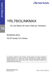
Saturn Starter
User Manual
Document Info
Product Manager
Martin Heimlicher (MH)
Author(s)
David Studer (DS), Marc Oberholzer (MO)
Reviewer(s)
Martin Heimlicher (MH), Christoph Glattfelder (CG)
Version
2.4
Date
12.04.2010
Enclustra GmbH – Technoparkstr. 1 – CH-8005 Zürich – Switzerland
Phone +41 43 343 39 43 – www.enclustra.com
Copyright reminder
Copyright © 2010 by Enclustra GmbH, Switzerland. All rights are reserved.
Unauthorized duplication of this document, in whole or in part, by any means is prohibited without the
prior written permission of Enclustra GmbH, Switzerland.
Although Enclustra GmbH believes that the information included in this publication is correct as of the
date of publication, Enclustra GmbH reserves the right to make changes at any time without notice.
All information in this document is strictly confidential and may only be published by Enclustra GmbH,
Switzerland.
All referenced trademarks are the property of their respective owners.
Document History
Version
Date
Author
Comment
2.40
12.04.2010
CG
Added warning about short-circuiting supply voltages on
the Apollo connectors
2.31
19.3.2010
CG
updated Apollo B1 pinout
2.3
16.11.2009
MO
Updated BAUD rate table with baud rates for Saturn SX1
Rev. B modules (Table 5, page 12)
2.2
15.06.2009
MO
Corrected USB UART baud rate table (Table 5, page 12)
Improved USB UART connectivity table (Table 4, page 11)
2.1
20.04.2009
MO
Corrected Saturn SX1 Apollo connector B1 pinout (Table 19,
page 20),
Updated BOM (Table 23, page 26)
2.0
01.04.2009
MO
Adapted to HW Rev. B
1.0
26.02.2009
DS
First release describing HW Rev. A
12.04.2010
2 / 29
Version 2.4
Table of Contents
1
Overview.......................................................................................................... 5
1.1
General.........................................................................................................................................5
1.2
Features .......................................................................................................................................5
1.3
Deliverables.................................................................................................................................5
1.4
Accessories ..................................................................................................................................6
1.4.1
1.4.2
1.4.3
Saturn Modules ........................................................................................................................................................6
Apollo Extension Cards..........................................................................................................................................6
IP Packages.................................................................................................................................................................6
1.5
Block Diagram ............................................................................................................................7
1.6
Board Top View ..........................................................................................................................8
2
Board Setup .................................................................................................... 9
2.1
Saturn Module Equipment........................................................................................................9
2.2
Apollo Extension Card Equipment...........................................................................................9
2.3
I/O Voltage Configuration ........................................................................................................9
2.3.1
2.3.2
2.3.3
Apollo Connector A1 I/O Voltage Configuration..................................................................................... 10
Apollo Connector A2 I/O Voltage Configuration..................................................................................... 10
Apollo Connectors B1 and B2 I/O Voltage Configuration.................................................................... 10
2.4
USB UART Configuration ........................................................................................................11
2.4.1
2.4.2
Connectivity ............................................................................................................................................................ 11
Baud Rate................................................................................................................................................................. 11
2.5
Powering the Board .................................................................................................................12
3
Connectors .................................................................................................... 13
3.1
Saturn Connectors (J501/J601)..............................................................................................13
3.2
Apollo Connectors (J502/J503/J602/J603)..........................................................................13
3.3
USB 2.0 and USB UART Connectors (J301/J302) ................................................................14
3.4
SD Card Slot (J402) ..................................................................................................................14
3.5
14-pin JTAG Connector (J303) ...............................................................................................14
3.6
10-pin JTAG Connector (J304) ...............................................................................................15
3.7
Power Connectors (J200/J201/J202) ....................................................................................16
3.8
Monitor UART Connector Footprint (J7)..............................................................................17
3.9
Module UART Connector Footprint (J6)...............................................................................17
4
Module Specific Information ...................................................................... 19
12.04.2010
3 / 29
Version 2.4
4.1
Saturn SX1 .................................................................................................................................19
4.1.1
4.1.2
4.1.3
4.1.4
Apollo Connectors Pinout ................................................................................................................................. 19
FPGA UART.............................................................................................................................................................. 21
VCCO Settings........................................................................................................................................................ 21
USB Availability...................................................................................................................................................... 22
5
Apollo Design Guidelines ............................................................................ 23
5.1
Power Requirements ...............................................................................................................23
5.2
Differential Pair Lengths .........................................................................................................23
5.3
Equipment Options ..................................................................................................................23
5.3.1
Differential Pair Termination ............................................................................................................................ 23
6
Assembly Drawing ....................................................................................... 25
7
Bill of Materials ............................................................................................ 26
8
Mechanical Drawing .................................................................................... 27
12.04.2010
4 / 29
Version 2.4
1
Overview
1.1
General
The Saturn Starter board represents the Saturn-specific part of the Apollo evaluation platform. It
provides slots for one Saturn module and up to four Apollo extension cards.
A series of Apollo extension cards provide ready-to-use peripheral functions for the most common
DSP and SoPC applications, enabling the rapid construction of prototyping systems.
The well-documented Apollo extension interface allows the creation of application-specific extension
cards for special functionalities not covered by the already available Apollo extension cards.
1.2
•
•
•
•
•
•
•
•
•
•
Features
One Saturn module slot
Four Apollo extension card slots
USB 2.0 high-speed interface (only for Saturn modules with integrated USB)
UART-over-USB for host PC connection
o Either connected to the Saturn module’s monitor port or
o to the Saturn module’s FPGA pins.
SD Card slot (FPGA configuration)
10- and 14-pin JTAG connectors
Saturn module I/O voltage selection
Reset button
Protected 12V power input with DC/DC converter to 5V
Optional 5V power input
1.3
•
•
•
•
•
•
Deliverables
Saturn Starter board
Saturn Starter user manual1 (this document)
Saturn Starter schematics2
3
Saturn Starter assembly drawing
USB cable
12V power supply
12.04.2010
5 / 29
Version 2.4
1.4
Accessories
1.4.1
Saturn Modules
•
Saturn SX1 – Xilinx Spartan-3A DSP FPGA module
1.4.2
•
•
•
•
•
•
Apollo Extension Cards
Apollo CV1 – Camera/Display: Camera Link, DVI, LVDS TFT
Apollo NS1 – Network and Connectivity: GigE, USB2.0, RS232, PS/2
Apollo DT1 – Touch Display: TFT, Touch, GPIO
Apollo DR1 – Drive/Motion Control: FET H-Bridges, Encoder, CAN, 24V I/O
Apollo AD1 – Data acquisition: High-speed ADCs
Apollo DA1 – Signal generation: High-speed DACs
1.4.3
•
IP Packages
TBD – TBD
12.04.2010
6 / 29
Version 2.4
1.5
Block Diagram
Apollo Extension Connector A1
12V In
Power
Conn.
12V
12V-5V
DC/DC
Conv.
5V
I/O
Voltage
Select
Apollo Extension Connector A2
SD
CARD
Slot
Saturn Module Connector A
UART
Mode
Select
FPGA UART
5V In
(opt)
Conn.
Reset
Button
FTDI
RS232
to USB
Monitor Port
12V In
(opt)
Conn.
USB 2.0
Conn.
2x
JTAG
Conn.
Saturn Module Connector B
Apollo Extension Connector B1
I/O
Voltage
Select
USB
UART
Conn.
Apollo Extension Connector B2
Figure 1: Hardware block diagram
One Saturn module and up to four Apollo extension cards may be plugged in to the Saturn Starter
board. The Saturn module connects through two 140-pin Hirose connectors while the Apollo extension
cards use 50-pin 2x2 mm dual row headers.
The Saturn Starter board provides a 12V power input connector for a standard 12V/2.5A power supply
(included). A DC/DC-converter generates 5V/3A from the 12V input. Instead of the included 12V/2.5A
power supply, a laboratory power supply may be connected through the 12V or 5V screw type
terminals.
The most common Saturn module / Apollo extension card I/O voltages are configurable via jumpers.
Externally generated custom I/O voltages may also be used.
An FTDI RS232 to USB device is integrated on the Saturn Starter board. This device enables host PC
access to the SD Card, the Saturn module’s monitor port or the Saturn module’s FPGA pins. The USB
UART connectivity and baud rate are configured via jumpers. Only one of the three USB UART targets
may be connected at a time.
The SD Card may be used to store FPGA configuration bitstreams as Saturn modules are able to boot
their FPGA from the SD Card. However, the Saturn Starter board does not provide the necessary
connections to use the SD Card as external FPGA memory. Only SPI mode is supported.
A 14-pin JTAG connector (suitable for Xilinx programming cables) as well as a 10-pin JTAG connector
(suitable for Altera programming cables) are equipped on the Saturn Starter board.
Additionally, a reset button is available on the Saturn Starter board. Pressing the reset button will
cause reboot of the equipped Saturn module, including re-configuration of the FPGA.
12.04.2010
7 / 29
Version 2.4
1.6
J4
Apollo Connector A2
J3
SD
Card
12V In
Saturn Connector A
USB
UART
8 / 29
12V In
(opt)
5V In
(opt)
J5
Saturn Connector B
J2
Apollo Connector B1
J1
Reset
JTAG
(14-pin)
Apollo Connector B2
USB
2.0
JTAG
(10-pin)
Board Top View
Figure 2: Saturn Starter board top view
12.04.2010
Apollo Connector A1
Version 2.4
2
Board Setup
2.1
Saturn Module Equipment
The Saturn connectors are keyed to prevent from equipping a Saturn module the wrong way.
Up to four M3 screws may be used to mechanically fasten a Saturn module to the Saturn Starter board.
Attention: Do not use excessive force to latch a Saturn module into the Saturn connectors on the Saturn
Starter board as this could damage the Saturn module as well as the Saturn Starter board. Always make
sure that the Saturn module is oriented the right way before plugging it into the Saturn Starter board.
2.2
Apollo Extension Card Equipment
There is no keying and no alignment help with the Apollo connectors, so care has to be taken at
plugging in an Apollo extension card.
Up to two M3 screws may be used to mechanically fasten an Apollo extension card to the Saturn
Starter board.
Attention: Be careful when connecting or measuring supply voltages on the Apollo connectors.
Connecting two supply voltages will destroy the Saturn FPGA module! Modules with failures due to faulty
operations like applying wrong voltages are not subject of any warranty.
Attention: Do not use excessive force to latch an Apollo extension card into the Apollo connectors on the
Saturn Starter board as this could damage the Apollo extension card as well as the Saturn Starter board.
Always make sure that the Apollo extension card is oriented the right way and properly aligned before
plugging it into the Saturn Starter board.
2.3
I/O Voltage Configuration
The Apollo connector I/O voltages are configurable to 2.5V or 3.3V via jumpers1. The Apollo connector
A1 and A2 I/O voltages are configurable independently while the Apollo connectors B1 and B2 share
the same I/O voltage.
The configured I/O voltage is available at pin 50 of the corresponding Apollo connector.
Attention: Only use I/O voltages compliant with the equipped Saturn module. Any other voltages may
damage the equipped Saturn module as well as equipped Apollo extension cards. Some Saturn modules
may have specific restrictions in terms of I/O voltage usage.
Attention: Do not leave an I/O voltage jumper middle pin floating. Doing so may damage the equipped
Saturn module as well as the equipped Apollo extension card.
1
Custom I/O voltages are also possible. The desired voltage must be applied to the according
jumper’s middle pin. The allowed I/O voltage levels are dependent on the equipped Saturn module.
12.04.2010
9 / 29
Version 2.4
2.3.1
Apollo Connector A1 I/O Voltage Configuration
Jumper J4 Position
A_VCCO_IN Configuration
Custom (desired I/O voltage must be connected to the jumper’s middle pin)
A_VCCO_IN = 3.3V (factory setting)
A_VCCO_IN = 2.5V
Table 1: A_VCCO_IN setting (jumper J4)
2.3.2
Apollo Connector A2 I/O Voltage Configuration
Jumper J3 Position
C_VCCO_IN Configuration
Custom (desired I/O voltage must be connected to the jumper’s middle pin)
C_VCCO_IN = 3.3V (factory setting)
C_VCCO_IN = 2.5V
Table 2: C_VCCO_IN setting (jumper J3)
2.3.3
Apollo Connectors B1 and B2 I/O Voltage Configuration
Jumper J2 Position
B_VCCO_IN Configuration
Custom (desired I/O voltage must be connected to the jumper’s middle pin)
B_VCCO_IN = 3.3V (factory setting)
B_VCCO_IN = 2.5V
Table 3: B_VCCO_IN setting (jumper J2)
12.04.2010
10 / 29
Version 2.4
2.4
USB UART Configuration
2.4.1
Connectivity
The USB UART connectivity is configured via jumper J5. Table 4 lists the three available configurations.
Jumper J5 Position
Configuration
UART: Not used
SD Card: Connected to the Saturn module’s monitor port
This setting allows FPGA configuration from the SD Card, but the UART
interface is inoperable.
UART: Connected to the Saturn module’s monitor port
SD Card: Not used
This setting allows access to the Saturn module’s monitor port over the UART,
but FPGA configuration from the SD Card is inoperable. The monitor port
uses 8 data bits, no parity bit, 1 stop bit and no flow control.
UART: Connected to the Saturn module’s FPGA UART pins
SD Card: Connected to the Saturn module’s monitor port
This setting allows access to the Saturn module’s FPGA UART pins over the
USB UART while FPGA configuration from the SD Card is available.
Table 4: USB UART connectivity select (jumper J5)
2.4.2
Baud Rate
Jumper J1 is used to select the USB UART baud rate. Table 5 shows the possible UART baud rate
configurations.
Jumper J1 Position
UART Baud Rate
38400 baud
4608002,3 / 750000 baud2,3
2
This baud rate is not supported by the monitor port. If this baud rate is selected when using the
monitor port, the baud rate is automatically reset to 38400 baud.
3
Saturn SX1 Rev. A modules run with 460800 baud while Saturn SX1 Rev. B modules run with 750000
baud.
12.04.2010
11 / 29
Version 2.4
115200 baud
Table 5: USB UART port baud rate select (jumper J1)
2.5
Powering the Board
12 V
J200
Input
Protection, Fuse,
TVS
12V -> 5V
DC/DC
Converter
5V / 3A
J201
J202
Figure 3: Power supply input
The Saturn Starter board provides a power supply input connector (J200) on board, which fits to the
included 12V / 2.5A power supply. The 12V input is protected against over voltage and over current. A
DC/DC converter is used to generate the 5 V voltage (max. 3 A).
In place of the included 12V power supply, a suitable laboratory power supply may be connected to
either the 12V (J201) or 5V (J202) screw type terminal. Please note that the 5V input is not protected
against over voltage and over current. Only one power input must be used at a time.
12.04.2010
12 / 29
Version 2.4
3
Connectors
3.1
Saturn Connectors (J501/J601)
Table 6 shows the connector type as well as some additional information.
Reference
Type
Description
Digikey part number
J501, J601
FX8-140P-SV(91)
Hirose FX8, 140-pin, 0.6 mm
pitch, 3mm stacking height
H10690-ND
Table 6: Saturn connector types
Figure 4 shows the pin numbering for the Saturn module connectors.
2
140
1
139
Figure 4: Pin numbering for the Saturn module connector (Saturn Starter board top view)
A detailed description of the Saturn connector pinout can be found in the respective user manual of
the equipped Saturn module.
3.2
Apollo Connectors (J502/J503/J602/J603)
Table 7 shows the connector type as well as some additional information.
Reference
Type
Description
Digikey part number
J502, J503, J602, J603
151250-2420-RB-WF
3M, 2x2mm, 50 pos, dual
row, male header, SMD
3M5376CT-ND
Female counterpart on
Apollo extensions
150250-2020-RB-WF
3M, 2x2mm, 50pos, dual row 3M5340CT-ND
female socket, SMD
Table 7: Apollo connector types
Figure 5 and Figure 6 show the pin numbering of the Apollo connectors. In top view, the pin
numbering of the B1/B2 connectors is rotated by 180° with respect to the A1/B2 connectors.
12.04.2010
13 / 29
Version 2.4
2
50
1
49
Figure 5: Pin numbering for Apollo connectors A1 and A2 (Saturn Starter board top view)
49
1
50
2
Figure 6: Pin numbering for Apollo connectors B1 and B2 (Saturn Starter board top view)
The actual pin usage/availability is dependent on the equipped Saturn FPGA Module. Section 4 gives
detailed information about the module-specific Apollo connector pinouts.
3.3
USB 2.0 and USB UART Connectors
(J301/J302)
Both connectors (J301/J302) are standard type B connectors as specified in the USB 2.0 specification.
3.4
4
SD Card Slot (J402)
The SD Card slot (J402) is a standard 32x24 mm SD Card slot as specified in the SD specifications.5
Only the SPI interface is connected, SD mode is thus not supported.
3.5
14-pin JTAG Connector (J303)
The 14-pin JTAG connector’s type and pinout are chosen to directly fit the Xilinx Platform Cable USB II
download cable. This connector should thus be used if a Saturn module incorporating a Xilinx FPGA is
equipped to the Saturn Starter board.
Table 8 shows the connector type as well as some additional information.
Reference
Type
Description
Digikey part number
J303
87832-1420
Molex dual row 14-pin header, SMD
WM18641-ND
Table 8: 14-pin JTAG connector type
12.04.2010
14 / 29
Version 2.4
Figure 7 shows the pin numbering for the 14-pin JTAG connector.
2
14
1
13
Figure 7: Pin numbering for the 14-pin JTAG connector (Saturn Starter board top view)
Table 9 shows the pinout of the 14-pin JTAG connector.
Pin number
Signal name
Pin number
Signal name
1
GND
2
VREF
3
GND
4
TMS
5
GND
6
TCK
7
GND
8
TDO
9
GND
10
TDI
11
GND
12
-
13
GND
14
-
Table 9: 14-pin JTAG connector pinout
3.6
10-pin JTAG Connector (J304)
The 10-pin JTAG connector’s type and pinout are chosen to directly fit the Altera USB Blaster
download cable. This connector should thus be used if a Saturn module incorporating an Altera FPGA
is equipped to the Saturn Starter board.
Table 10 shows the connector type as well as some additional information.
Reference
Type
Description
Digikey part number
J304
5103308-1
Tyco dual row 10-pin header, THT
A33159-ND
Table 10: 10-pin JTAG connector type
Figure 8 shows the pin numbering for the 10-pin JTAG connector.
12.04.2010
15 / 29
Version 2.4
2
10
1
9
Figure 8: Pin numbering for the 10-pin JTAG connector (Saturn Starter board top view)
Table 11 shows the pinout of the 10-pin JTAG connector.
Pin number
Signal name
Pin number
Signal name
1
TCK
2
GND
3
TDO
4
VCC
5
TMS
6
-
7
-
8
-
9
TDI
10
GND
Table 11: 10-pin JTAG connector pinout
3.7
Power Connectors (J200/J201/J202)
Table 12 shows the connector type as well as some additional information.
Reference
Type
Description
Digikey part number
J200
PJ-002AH-SMT
CUI power jack connector SMD
CP-002AHPJCT-ND
J201, J202
MKDSN 1,5/2-5,08
Phoenix screw type print header, 2pol,
5.08mm
-
Table 12: Power connector types
Figure 9 shows the power/GND connections for the power connectors in Saturn Starter board front
view.
J200
12V GND
J201
J202
12V GND 5V GND
Figure 9: Power/GND connections for the power connectors (Saturn Starter board front view)
12.04.2010
16 / 29
Version 2.4
3.8
Monitor UART Connector Footprint (J7)
Attention: The monitor UART connector J7 is not equipped by default and has – if required - to be
equipped by the user.
The Monitor UART connector pins are not connected to any Apollo connector and are powered by
VCC_3V3.
Table 13 shows the connector type as well as some additional information.
Reference
Type
Description
Digikey part number
J7
22-03-2051
Molex pin header, 5 x 2.54 mm pitch
WM4003-ND
Table 13: Monitor UART connector type
Figure 10 shows monitor UART connector footprint (J7) as seen in Saturn Starter board top view.
1 2 3 4 5
Figure 10: Monitor UART connector footprint (Saturn Starter board top view)
Table 14 shows the pinout of the monitor UART connector.
Pin number
Signal name
1
MON_CTS#
2
MON_RTS#
3
GND
4
MON_RX
5
MON_TX
Table 14: Monitor UART connector pinout
3.9
Module UART Connector Footprint (J6)
Attention: The module UART connector J6 is not equipped by default and has - if required - to be
equipped by the user.
The Module UART connector pins are not connected to any Apollo connector and are powered by
B_VCCO_IN.
Table 15 shows the connector type as well as some additional information.
12.04.2010
17 / 29
Version 2.4
Reference
Type
Description
Digikey part number
J6
22-03-2051
Molex pin header, 5x 2.54mm pitch
WM4003-ND
Table 15: Module UART connector type
Figure 11 shows module UART connector footprint (J6) as seen in Saturn Starter board top view.
5 4 3 2 1
Figure 11: Monitor UART connector footprint (Saturn Starter board top view)
Table 16 shows the pinout of the monitor UART connector.
Pin number
Signal name
Module connector pins
1
B_DIFFIO_N_9
B30
2
B_DIFFOP_P_9
B28
3
GND
4
B_DIFFIO_N_0
B5
5
B_DIFFIO_P_0
B3
Table 16: Module UART connector pinout
12.04.2010
18 / 29
Version 2.4
4
Module Specific Information
4.1
Saturn SX1
4.1.1
Apollo Connectors Pinout
4.1.1.1
Apollo Connector A1
FPGA
Pin
B3
D5
B4
C6
A6
E7
C7
B6
F8
C8
A8
G8
A9
C9
C5
A10
-
FPGA
I/O
IO_L30P_0
IO_L29P_0
IO_L28P_0
IO_L21P_0
IO_L25P_0
IO_L31P_0/VREF_0
IO_L26P_0
IO_L24P_0
IO_L27P_0
IO_L22P_0
IO_L20P_0/GCLK10
IO_L23P_0
IO_L18P_0/GCLK6
IO_L16P_0
IP_0
IP_0
-
Signal
A_DiffIo_P<0>
A_DiffIo_P<1>
A_DiffIo_P<2>
A_DiffIo_P<3>
GND
A_DiffIo_P<4>
A_DiffIo_P<5>
A_DiffIo_P<6>
A_DiffIo_P<7>
GND
A_DiffIo_P<8>
A_DiffIo_P<9>
A_DiffIo_P<10>
A_DiffIo_P<11>
GND
A_DiffIo_P<12>
A_DiffIo_P<13>
A_Input<0>
A_Input<2>
GND
Clk_Out<0>
GND
VCC_1V2_Out
VCC_1V8_Out
VCC_2V5_Out
Connector A1
Pin
12
34
56
78
9 10
11 12
13 14
15 16
17 18
19 20
21 22
23 24
25 26
27 28
29 30
31 32
33 34
35 36
37 38
39 40
41 42
43 44
45 46
47 48
49 50
Signal
A_DiffIo_N<0>
A_DiffIo_N<1>
A_DiffIo_N<2>
A_DiffIo_N<3>
GND
A_DiffIo_N<4>
A_DiffIo_N<5>
A_DiffIo_N<6>
A_DiffIo_N<7>
GND
A_DiffIo_N<8>
A_DiffIo_N<9>
A_DiffIo_N<10>
A_DiffIo_N<11>
GND
A_DiffIo_N<12>
A_DiffIo_N<13>
A_Input<1>
A_Input<3>
GND
GND
GND
VCC_3V3_Out
VCC_5V0
A_VCCO_In
FPGA
I/O
IO_L30N_0
IO_L29N_0
IO_L28N_0
IO_L21N_0
IO_L25N_0
IO_L31N_0/PUDC_B
IO_L26N_0
IO_L24N_0/VREF_0
IO_L27N_0
IO_L22N_0
IO_L20N_0/GCLK11
IO_L23N_0
IO_L18N_0/GCLK7
IO_L16N_0
IP_0
IP_0/VREF_0
-
FPGA
Pin
A3
C4
A4
D6
A5
F7
D7
A7
E8
D9
B8
F9
B9
D10
C10
C11
-
Table 17: Saturn SX1 Apollo A1 connector pinout
12.04.2010
19 / 29
Version 2.4
4.1.1.2
FPGA
Pin
E13
F14
D14
A14
D15
E15
A16
E16
C18
B17
D19
B20
F10
E12
C13
A13
-
Apollo Connector A2
FPGA
I/O
IO_L09P_0
IO_L13P_0
IO_L12P_0
IO_L10P_0
IO_L08P_0
IO_L05P_0
IO_L06P_0/VREF_0
IO_L04P_0
IO_L02P_0/VREF_0
IO_L03P_0
IO_L01P_0
IO_L07P_0
IO_L19P_0/GCLK8
IO_L17P_0/GCLK4
IO_L14P_0
IO_L11P_0
-
Signal
A_DiffIo_P<19>
A_DiffIo_P<20>
A_DiffIo_P<21>
A_DiffIo_P<22>
GND
A_DiffIo_P<23>
A_DiffIo_P<24>
A_DiffIo_P<25>
A_DiffIo_P<26>
GND
A_DiffIo_P<27>
A_DiffIo_P<28>
A_DiffIo_P<29>
A_DiffIo_P<30>
GND
A_DiffIo_P<14>
A_DiffIo_P<16>
A_DiffIo_P<17>
A_DiffIo_P<18>
GND
Clk_Out<1>
GND
VCC_1V2_Out
VCC_1V8_Out
VCC_2V5_Out
Connector A2
Pin
12
34
56
78
9 10
11 12
13 14
15 16
17 18
19 20
21 22
23 24
25 26
27 28
29 30
31 32
33 34
35 36
37 38
39 40
41 42
43 44
45 46
47 48
49 50
Signal
Connector B1
Pin
12
34
56
78
9 10
11 12
13 14
15 16
17 18
19 20
21 22
23 24
25 26
27 28
29 30
31 32
33 34
35 36
37 38
39 40
41 42
43 44
45 46
47 48
49 50
Signal
A_DiffIo_N<19>
A_DiffIo_N<20>
A_DiffIo_N<21>
A_DiffIo_N<22>
GND
A_DiffIo_N<23>
A_DiffIo_N<24>
A_DiffIo_N<25>
A_DiffIo_N<26>
GND
A_DiffIo_N<27>
A_DiffIo_N<28>
A_DiffIo_N<29>
A_DiffIo_N<30>
GND
A_DiffIo_N<14>
A_DiffIo_N<16>
A_DiffIo_N<17>
A_DiffIo_N<18>
GND
GND
GND
VCC_3V3_Out
VCC_5V0
C_VCCO_In
FPGA
I/O
IO_L09N_0
IO_L13N_0
IO_L12N_0/VREF_0
IO_L10N_0
IO_L08N_0
IO_L05N_0
IO_L06N_0
IO_L04N_0
IO_L02N_0
IO_L03N_0
IO_L01N_0
IO_L07N_0
IO_L19N_0/GCLK9
IO_L17N_0/GCLK5
IO_L14N_0
IO_L11N_0
-
FPGA
Pin
D13
F13
C15
B15
C16
F15
A17
F16
B19
C17
C19
A19
E11
F11
C12
B13
-
FPGA
I/O
IO_L30N_2
IO_L27N_2
IO_L23N_2
IO_L28N_2
IO_L29N_2
IO_L25N_2
IO_L19N_2
IO_L21N_2
IO_L13N_2
IO_L10N_2
IO_L08N_2
IO_L06N_2
IO_L17N_2/GCLK1
IO_L11N_2
IO_L05N_2
IO_L04N_2
-
FPGA
Pin
AB20
AA19
AB18
V16
Y16
U15
AB14
W14
Y9
U9
AA8
V8
V12
U8
AB6
AA4
-
Table 18: Saturn SX1 Apollo A2 connector pinout
4.1.1.3
FPGA
Pin
AA20
AB19
AB17
U16
Y17
U14
AA15
Y13
Y8
V10
AB7
W8
U12
V7
AB5
AB4
-
Apollo Connector B1
FPGA
I/O
IO_L30P_2
IO_L27P_2
IO_L23P_2
IO_L28P_2
IO_L29P_2
IO_L25P_2
IO_L19P_2
IO_L21P_2
IO_L13P_2
IO_L10P_2
IO_L08P_2
IO_L06P_2
IO_L17P_2/GCLK0
IO_L11P_2
IO_L05P_2
IO_L04P_2
-
Signal
B_DiffIo_P<17>
B_DiffIo_P<16>
B_DiffIo_P<15>
B_DiffIo_P<14>
GND
B_DiffIo_P<13>
B_DiffIo_P<12>
B_DiffIo_P<11>
B_DiffIo_P<10>
GND
B_DiffIo_P<7>
B_DiffIo_P<6>
B_DiffIo_P<5>
B_DiffIo_P<4>
GND
B_DiffIo_P<8>
B_DiffIo_P<3>
B_DiffIo_P<2>
B_DiffIo_P<1>
GND
Clk_Out<2>
GND
VCC_1V2_Out
VCC_1V8_Out
VCC_2V5_Out
B_DiffIo_N<17>
B_DiffIo_N<16>
B_DiffIo_N<15>
B_DiffIo_N<14>
GND
B_DiffIo_N<13>
B_DiffIo_N<12>
B_DiffIo_N<11>
B_DiffIo_N<10>
GND
B_DiffIo_N<7>
B_DiffIo_N<6>
B_DiffIo_N<5>
B_DiffIo_N<4>
GND
B_DiffIo_N<8>
B_DiffIo_N<3>
B_DiffIo_N<2>
B_DiffIo_N<1>
GND
GND
GND
VCC_3V3_Out
VCC_5V0
B_VCCO_In
Table 19: Saturn SX1 Apollo B1 connector pinout
12.04.2010
20 / 29
Version 2.4
4.1.1.4
FPGA
Pin
J21
L18
R21
R17
V22
W21
T18
W19
C22
H21
W18
V15
W13
AB11
W9
AA6
-
Apollo Connector B2
FPGA
I/O
IP_L27P_1
IP_L23P_1/VREF_1
IP_L16P_1/VREF_1
IP_L12P_1
IP_L08P_1
IP_L04P_1
IO_L05P_1
IO_L03P_1/A0
IP_L39P_1/VREF_1
IP_L31P_1/VREF_1
IP_2/VREF_2
IP_2/VREF_2
IP_2/VREF_2
IP_2/VREF_2
IP_2/VREF_2
IP_2
-
Connector B2
Pin
12
34
56
78
9 10
11 12
13 14
15 16
17 18
19 20
21 22
23 24
25 26
27 28
29 30
31 32
33 34
35 36
37 38
39 40
41 42
43 44
45 46
47 48
49 50
Signal
B_UserIn_P<5>
B_UserIn_P<4>
B_UserIn_P<3>
B_UserIn_P<2>
GND
B_UserIn_P<1>
B_UserIn_P<0>
B_UserIo_P<1>
B_UserIo_P<0>
GND
B_UserIn_P<7>
B_UserIn_P<6>
B_Input<13>
B_Input<11>
GND
B_Input<9>
B_Input<7>
B_Input<5>
B_Input<3>
GND
Clk_Out<2>
GND
VCC_1V2_Out
VCC_1V8_Out
VCC_2V5_Out
Signal
B_UserIn_N<5>
B_UserIn_N<4>
B_UserIn_N<3>
B_UserIn_N<2>
GND
B_UserIn_N<1>
B_UserIn_N<0>
B_UserIo_N<1>
B_UserIo_N<0>
GND
B_UserIn_N<7>
B_UserIn_N<6>
B_Input<12>
B_Input<10>
GND
B_Input<8>
B_Input<6>
B_Input<4>
B_Input<2>
GND
GND
GND
VCC_3V3_Out
VCC_5V0
B_VCCO_In
FPGA
I/O
IP_L27N_1
IP_L23N_1
IP_L16N_1
IP_L12N_1/VREF_1
IP_L08N_1/VREF_1
IP_L04N_1/VREF_1
IO_L05N_1
IO_L03N_1/A1
IP_L39N_1
IP_L31N_1
IP_2
IP_2/VREF_2
IP_2
IP_2
IP_2
IP_2
-
FPGA
Pin
J22
K17
P20
P17
U21
W20
T17
V20
C21
G20
AB15
Y14
Y12
W10
Y7
Y6
-
Table 20: Saturn SX1 Apollo B2 connector pinout
4.1.2
FPGA UART
UART signal
Connected to Signal
FPGA Pin
FPGA Location
UART connector pin
FTDI_RTS#
B_DIFFIO_N_9
AA14
I/O_L18N_2/GCLK3 1
FTDI_CTS#
B_DIFFIO_P_9
AB13
I/O_L18P_2/GCLK2 2
FTDI_TX
B_DIFFIO_N_0
Y4
I/O_L03N_2
5
FTDI_RX
B_DIFFIO_P_0
W5
I/O_L03P_2
4
Table 21: FPGA UART pinout
Please note that the FPGA UART pins are only available with the correct jumper settings. Please see
section 2.4.1 for details.
4.1.3
VCCO Settings
The FPGA I/Os routed to the Apollo connectors A1 and A2 are all connected to the same FPGA bank
(bank 0). Therefore, the I/O voltages of the Apollo connectors A1 and A2 must be the same.
Attention: Always set A_VCCO_IN and C_VCCO_IN to the same voltage!
12.04.2010
21 / 29
Version 2.4
4.1.4
USB Availability
The USB 2.0 interface is available with the Saturn SX1-3400 module, but not with the Saturn SX1-1800
module.
12.04.2010
22 / 29
Version 2.4
5
Apollo Design Guidelines
5.1
Power Requirements
The 1.2V / 1.8V / 2.5V and 3.3V supplies are generated within the Saturn module and directly taken
from the Saturn module power outputs. The available currents must be shared between all equipped
Apollo extensions cards. The available power depends on the module used. Please see the respective
Saturn module user manual for detailed information.
For the 5V supply, a total of 3A are available for the Saturn module and the equipped Apollo extension
cards together. The available power depends on the module used. Please see the respective Saturn
module user manual for detailed information.
In conclusion, if an Apollo extension card requires a lot of power on 1.2V, 1.8V, 2.5 V and/or 3.3V, the
respective voltages have to be generated from the 5V power input, or a separate power input has to
be integrated into the Apollo extension card.
5.2
Differential Pair Lengths
All differential pairs on the Saturn Starter board are length matched to 99 mm.
5.3
Equipment Options
5.3.1
Differential Pair Termination
Footprints for parallel termination resistors (0402) on all differential pairs close to the module
connectors are available on the Saturn Starter board. However, these termination resistors are not
equipped by default and have – if required – to be equipped by the user
Signal
Resistor
Signal
Resistor
Signal
Resistor
A_DIFFIO_X_0
R700
A_DIFFIO_X_21
R720
B_DIFFIO_X_12
R740
A_DIFFIO_X_1
R701
A_DIFFIO_X_22
R721
B_DIFFIO_X_13
R741
A_DIFFIO_X_2
R702
A_DIFFIO_X_23
R722
B_DIFFIO_X_14
R742
A_DIFFIO_X_3
R703
A_DIFFIO_X_24
R723
B_DIFFIO_X_15
R743
A_DIFFIO_X_4
R704
A_DIFFIO_X_25
R724
B_DIFFIO_X_16
R744
A_DIFFIO_X_5
R705
A_DIFFIO_X_26
R725
B_DIFFIO_X_17
R745
A_DIFFIO_X_6
R706
A_DIFFIO_X_27
R726
B_USERIN_X_0
R746
A_DIFFIO_X_7
R707
A_DIFFIO_X_28
R727
B_USERIN_X_1
R747
12.04.2010
23 / 29
Version 2.4
A_DIFFIO_X_8
R708
A_DIFFIO_X_29
R728
B_USERIN_X_2
R748
A_DIFFIO_X_9
R709
A_DIFFIO_X_30
R729
B_USERIN_X_3
R749
A_DIFFIO_X_10
R710
B_DIFFIO_X_1
R730
B_USERIN_X_4
R750
A_DIFFIO_X_11
R711
B_DIFFIO_X_2
R731
B_USERIN_X_5
R751
A_DIFFIO_X_12
R712
B_DIFFIO_X_3
R732
B_USERIN_X_6
R752
A_DIFFIO_X_13
R713
B_DIFFIO_X_4
R733
B_USERIN_X_7
R753
A_DIFFIO_X_14
R714
B_DIFFIO_X_5
R734
B_USERIN_X_6
R754
A_DIFFIO_X_16
R715
B_DIFFIO_X_6
R735
B_USERIN_X_7
R755
A_DIFFIO_X_17
R716
B_DIFFIO_X_7
R736
B_USERIO_X_0
R756
A_DIFFIO_X_18
R717
B_DIFFIO_X_8
R737
B_USERIO_X_1
R757
A_DIFFIO_X_19
R718
B_DIFFIO_X_10
R738
A_DIFFIO_X_20
R719
B_DIFFIO_X_11
R739
Table 22: Differential pairs termination resistors
12.04.2010
24 / 29
Version 2.4
6
Assembly Drawing
Figure 12: Assembly drawing
12.04.2010
25 / 29
Version 2.4
7
Bill of Materials
Reference
C201-202
Part Number
-
Value
4n7
Tolerance
250V X7R 10%
Description
Capacitor ceramic 4700PF 250V X7R
Manufacturer
TDK Corporation
C203-204 C304
C205-206
C207
C208-209
C210
C301-303 C306-307
C400 C402-405
C305
-
10u
22u
4n7
100u
1u
1u
16V X5R 10%
6.3V X5R
50V X7R
16V ±10%
16V
6V3 X5R
10% 0805
SMD Capacitor
SMD Capacitor
SMD Capacitor
SMD Tantalum Capacitor low ESR
SMD Capacitor
SMD Capacitor
Murata
Kemet
Kemet
Panasonic
-
4n7*
250V X7R 10%
Capacitor ceramic 4700PF 250V X7R
TDK Corporation
10% 0805
SMD Capacitor
TVS 600W 13V UNIDIRECT
ESD Protector bidir 0402 14VDC
Polyswitch 1.50A Hold SMD
CONN HEADER 3POS .100" VERT
SHUNT .100" BLACK
CONN POWER JACK 2.1X5.5MM HI
Micro Commercial Co
Tyco Electronics
Tyco Electronics
Molex
On Shore Technology Inc
CUI Inc
C401
D201
D300-303
F201
J1-5
J1B J2B J3B J4B J5B
J200
SMBJ13A-TP
PESD0402-140
SMD150F-2
68301-1014
EDJ2G0
PJ-002AH-SMT
1n *
-
50V X7R
13.0V
1.5A
-
J201-202
MKDSN 1,5/2-5,08
-
-
J203-206
J301-302
J303
S1751_46
1734346-1
87832-1420
-
-
J304
5103308-1
-
-
J400
J402
44144-0005*
SD-RSMT-2-MQ-WF
-
-
J501 J601
FX8-140P-SV
-
-
J502-503 J602-603
151250-2420-RB-WF
-
-
Module Connector, 140-Pin Hirose
Hirose
FX8
Connector 50Pos 2mm HEADER SMD 3M
J6-7
L201 L501-502 L601-602 BLM18SG121TN1D
1x5 2.54mm*
-
120R@100MHz 0.025
Pin Header 1X5 254
Ferrite, 3A, 120R@100MHz, 0.025R
Murata
L202
DLW5BSN191SQ2L
-
DCR
50V 5.0A
DCR
SMD EMI Filters/Chip Ferrite Beads
Murata Electronics
L203
L301-302
DLP11SN900HL2L
3uH
-
+/- 30%
-
50V 5.0A COMMON MODE
SMD inductor
CHOKE COIL COMMON MODE
Taiyo Yuden
Murata Electronics North America
LED201 LED601
LED301-302
R201 R401-402 R409
R202
R203
R204
R301
R302
R303-304
R305 R400
R403-404 R406 R408
SML-P12PTT86
SML-P12YTT86
-
82k
12k
18k
680R
4k7
10k
470R
0R
10k
13mcd 2.2V 20mA
130mcd 2.1V 20mA
1%
1%
1%
1%
1%
1%
1%
1%
150MA SMD
LED 0402 Green
LED 0402 Yellow
SMD Resistor
SMD Resistor
SMD Resistor
SMD Resistor
SMD Resistor
SMD Resistor
SMD Resistor
SMD Resistor
SMD Resistor
Rohm
Rohm
-
R410 R412-416
R405
R407
R411
R417-420
R601-602
R605
R700-755
S400
FSM4JSMA
39k
22k
10k *
100R
18R
270R
100R *
-
1%
1%
1%
1%
1%
1%
1%
-
SMD Resistor
SMD Resistor
SMD Resistor
SMD Resistor
SMD Resistor
SMD Resistor
SMD Resistor
Tactile Switch, 6x6mm, 160g,
Tyco Electronics
U201
U303
U400-403
ST1S10PUR
FT232RQ R
NC7WB66K8X
-
-
50mA@12V
IC REG STEPDOWN 3A 900KHZ
IC USB TO SERIAL UART
Dual bus switch
STMicroelectronics
FTDI
Fairchild
CUR
Printheader 2x5.08mm,low profile,
Schraubenanschluss
SMT Test Point
USB Type B receptacle, SMD
2x7 pin 2mm SMD JTAG connector
Phoenix Contact
Harwin
Tyco Electronics
Molex
Tyco Electronics
Connector header 10 pos, JTAG
Altera
Connector Jack 6/6Pos Gold
Molex
Connector SD-Card PUSH-PUSH SMD 3M
Table 23: Bill of materials
12.04.2010
26 / 29
Version 2.4
72
2
1
18
8
72
50
49
2
1
Connector Apollo A1
50
49
Connector Apollo A2
M3 Screwholes
x6
2
1
Connector A
Hirose FX8-140P-SV
M3 Screwholes
x8
140
139
2
Connector B
Hirose FX8-140P-SV
140
139
37.5
1
98
120
106
42
27 / 29
Limited
component
height area
Connector Apollo B1
49
50
Version 2.4
40
90
61.9
170
1
2
11
Connector Apollo B2
1
2
7
49
50
Mechanical Drawing
Figure 13: Mechanical drawing (all units in mm)
12.04.2010
4
Figures
Figure 1: Hardware block diagram..........................................................................................................................................7
Figure 2: Saturn Starter board top view................................................................................................................................8
Figure 3: Power supply input.................................................................................................................................................. 12
Figure 4: Pin numbering for the Saturn module connector (Saturn Starter board top view)....................... 13
Figure 5: Pin numbering for Apollo connectors A1 and A2 (Saturn Starter board top view)....................... 14
Figure 6: Pin numbering for Apollo connectors B1 and B2 (Saturn Starter board top view) ....................... 14
Figure 7: Pin numbering for the 14-pin JTAG connector (Saturn Starter board top view)............................ 15
Figure 8: Pin numbering for the 10-pin JTAG connector (Saturn Starter board top view)............................ 16
Figure 9: Power/GND connections for the power connectors (Saturn Starter board front view)............... 16
Figure 10: Monitor UART connector footprint (Saturn Starter board top view) ................................................ 17
Figure 11: Monitor UART connector footprint (Saturn Starter board top view) ................................................ 18
Figure 12: Assembly drawing ................................................................................................................................................. 25
Figure 13: Mechanical drawing (all units in mm)............................................................................................................ 27
Tables
Table 1: A_VCCO_IN setting (jumper J4)............................................................................................................................ 10
Table 2: C_VCCO_IN setting (jumper J3) ............................................................................................................................ 10
Table 3: B_VCCO_IN setting (jumper J2) ............................................................................................................................ 10
Table 4: USB UART connectivity select (jumper J5) ....................................................................................................... 11
Table 5: USB UART port baud rate select (jumper J1) .................................................................................................. 12
Table 6: Saturn connector types ........................................................................................................................................... 13
Table 7: Apollo connector types ........................................................................................................................................... 13
Table 8: 14-pin JTAG connector type.................................................................................................................................. 14
Table 9: 14-pin JTAG connector pinout ............................................................................................................................. 15
Table 10: 10-pin JTAG connector type ............................................................................................................................... 15
Table 11: 10-pin JTAG connector pinout........................................................................................................................... 16
Table 12: Power connector types ......................................................................................................................................... 16
Table 13: Monitor UART connector type ........................................................................................................................... 17
Table 14: Monitor UART connector pinout....................................................................................................................... 17
Table 15: Module UART connector type............................................................................................................................ 18
Table 16: Module UART connector pinout ....................................................................................................................... 18
12.04.2010
28 / 29
Version 2.4
Table 17: Saturn SX1 Apollo A1 connector pinout ........................................................................................................ 19
Table 18: Saturn SX1 Apollo A2 connector pinout ........................................................................................................ 20
Table 19: Saturn SX1 Apollo B1 connector pinout ........................................................................................................ 20
Table 20: Saturn SX1 Apollo B2 connector pinout ........................................................................................................ 21
Table 21: FPGA UART pinout.................................................................................................................................................. 21
Table 22: Differential pairs termination resistors ........................................................................................................... 24
Table 23: Bill of materials......................................................................................................................................................... 26
References
1
Saturn Starter User Manual, Enclustra GmbH, 2009, www.enclustra.com/saturnstarter
2
Saturn Starter Schematics, Enclustra GmbH, 2009, www.enclustra.com/saturnstarter
3
Saturn Starter Assembly Drawing, Enclustra GmbH, 2009, www.enclustra.com/saturnstarter
4
USB 2.0 Specification, USB-IF, 2000, http://www.usb.org/developers/docs/
5
SD Specifications 2.0, SD Group, 2006, http://www.sdcard.org/developers/tech/sdcard/
12.04.2010
29 / 29
Version 2.4