1
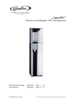
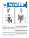
HTC Technical Manual
Marco Denicolai
10.04.2009
HTC Technical Manual
Marco Denicolai
Table of contents
1.
2.
General .....................................................................................................................................................3
Technical details.......................................................................................................................................3
2.1. Primary winding ...............................................................................................................................3
2.2. Secondary winding ...........................................................................................................................3
2.3. Top terminal .....................................................................................................................................3
2.4. Rotary spark gap...............................................................................................................................3
2.5. Safety spark gap ...............................................................................................................................4
3. Measurements...........................................................................................................................................5
3.1. Primary circuit ..................................................................................................................................5
3.2. Secondary circuit ..............................................................................................................................5
3.3. Coupling coefficient .........................................................................................................................5
4. Estimated values.......................................................................................................................................6
4.1. Power consumption ..........................................................................................................................6
4.2. Maximum output voltage..................................................................................................................6
5. Electrical schematic diagram....................................................................................................................7
6. Periodical maintenance and servicing ......................................................................................................7
7. Replacement part list ................................................................................................................................9
_____________________________________________________________________________________
2
HTC Technical Manual
1.
Marco Denicolai
General
The HTC is a small sized Tesla Coil intended for educative purposes and composed by (see Figure 1):
500.00 mm
•
•
•
•
a top terminal
a primary winding
a secondary winding
a base block.
TOP TERMINAL
SECONDARY
WINDING
1030.00 mm
These four components can be easily separated from each other
by removing a few screws for transportation of the HTC or for
their replacement if damaged.
PRIMARY
WINDING
The HTC base block contains a high voltage (HV) generator, a
capacitor bank and a rotary spark gap.
The primary winding is placed on the top of the base block and
connected to it by two thick wires. The secondary winding is
placed in the middle of the primary winding, vertically on the
HTC base block. The top terminal is a toroid located on the top
of the secondary winding. Electrical discharges are generated
from its surface in random directions.
BASE BLOCK
400.00 mm
Figure 1. HTC components.
2.
Technical details
2.1.
Primary winding
8 turns of 4.8 mm copper tube, inner diameter 150 mm, turn spacing 7.7 mm. Flat pancake (Figure 7).
Inductance 18.6 µH (max, by design). Clearance from inner turn to secondary 20 mm.
2.2.
Secondary winding
110 mm diameter gray PP pipe, 500 mm wound with AWG 26 (0.4 mm) grade 2 enamel wire, 7 layers of
lacquer paint (Dolphs AC-43 polyester varnish). Calculated values: 1139 turns, inductance 28.1 mH, self
capacitance 8.28 pF. The secondary mounts on the HTC base using a push-and-twist lock with springs and
copper plate electrodes for the bottom grounding.
2.3.
Top terminal
A toroid using 100 mm diameter aluminum flexible duct, laminated with elastic cloth band, polyester resin
and aluminum tape. 500 mm outer diameter, calculated capacitance 21 pF.
2.4.
Rotary spark gap
A 120 mm diameter disk of fiber bakelite, 8 mm thick, with 12 rotating tungsten electrodes (4 mm thick).
Each electrode is mounted on an M8 bolt-nut pair and secured by two set screws (Figure 5). All electrodes
are connected by a brass ring (Figure 4). A pair of fixed electrodes is mounted on a support made of Teflon
and PVC. The AC motor runs at 2800 RPM and ensures a break rate of:
BPS =
speed ⋅ 6 2800 ⋅ 6
=
= 280 breaks/s
60
60
_____________________________________________________________________________________
3
HTC Technical Manual
2.5.
Marco Denicolai
Figure 2. Secondary winding mount.
Figure 3. Secondary winding base connection.
Figure 4. RSG rotor.
Figure 5. RSG electrodes.
Figure 6. Safety spark gap.
Figure 7. Primary winding.
Safety spark gap
The safety spark gap is made of four brass electrodes (Figure 6). The two electrodes in the middle are fixed
and grounded, while the external two are movable and locked in suitable position by two nuts.
_____________________________________________________________________________________
4
HTC Technical Manual
Marco Denicolai
3.
Measurements
3.1.
Primary circuit
The primary capacitor Cp value was measured as 48.4 nF (@ 1 kHz, 1 V). The primary winding and the
primary capacitors were connected in parallel and their resonant frequency measured as from Table 1 (fres
column) at different tap positions. The primary winding inductance was calculated as:
Lcalc =
1
2
C p (2πf res )
Table 1. Primary winding measurements.
Turns
8.0
7.5
6.5
5.5
4.5
3.5
2.5
1.5
1.0
0.5
fres [kHz]
170
178
204
240
282
340
422
530
600
654
Lcalc [uH]
18.11
16.52
12.58
9.09
6.58
4.53
2.94
1.86
1.45
1.22
Lmeas [uH]
16
5.8
0.7
The primary winding inductance was also measured for verification at three tap positions (Lmeas at 7.5, 4.5
and 1.5 turns). As the direct measurement was pretty difficult with the available instrumentation, the
calculated values were assumed more reliable and in good accordance with the designed ones.
3.2.
Secondary circuit
The secondary winding inductance was measured directly as 27.1 mH (@ 1 kHz, 1 V) and assumed in good
accordance with the designed 28.1 mH.
3.3.
Coupling coefficient
The mutual inductance and coupling coefficient and primary and secondary windings were calculated by
measuring the inductance of their series at different primary heights. The primary height was defined as the
distance between the base block top and the primary polycarbonate panel, that is, as the height of the
primary winding supports. As the measurement was uncertain with the available instrumentation, only three
points were collected (Table 2) and calculated as:
M=
Lt − (L1 + L2 )
2
k=
M
L1 L2
where L1, L2 and Lt are, respectively, the inductance of primary winding, secondary winding and their
measured series. M is the mutual inductance and k the coupling coefficient.
_____________________________________________________________________________________
5
HTC Technical Manual
Marco Denicolai
Table 2. Coupling coefficient estimation.
Height [mm]
37
120
200
L1 [uH]
19.7
19.7
19.7
Lt [mH]
27.2
27.4
27.5
M [uH]
40.15
140.15
190.15
k
0.056
0.192
0.260
Note that in the table above the primary was tapped at 8 turns and the measurement wires inductance was
not subtracted from the measured values.
4.
Estimated values
4.1.
Power consumption
The power consumption on MF1 is given by its only load, the rotary spark gap motor and estimated as
90W. The average power consumption on MF2 can be roughly estimated as:
(
)
2
2
PMF 2 = 0.5 ⋅ C p ⋅ V peak
⋅ BPS = 0.5 ⋅ 48.4 E − 9 ⋅ 8000 ⋅ 2 ⋅ 280 = 862 W
4.2.
Maximum output voltage
Estimation of the HTC maximum output voltage is quite a difficult task, as well as its direct or even indirect
measurement. To gain some understanding at least about its order of magnitude, the following equation can
be used:
Vout = V peak
L2
27.1E − 3
= 8000 ⋅ 2 ⋅
= 457 kV
L1
16.52 E − 6
_____________________________________________________________________________________
6
HTC Technical Manual
5.
Marco Denicolai
Electrical schematic diagram
The HTC complete schematic diagram can be found in Figure 8. The components inside the dotted box are
assembled on a printed circuit board. Main feed 2 (MF2) supplies transformers T1 and T2 through line filter
LF1. C5, D1 and D2 form a voltage doubler that rises the output of T1 from 2 to 4 kV AC. C6, D3 and D4
implement the same function for T2. The total voltage developed upon SG1 is therefore 8 kV AC. C1-C4
and R1-R4 are snubbers to protect D1-D4 from voltage transients.
Motor MG1 rotates the RSG1 rotary spark gap. The HV power supply voltage charges the HV capacitors
C7 and C8 through LP. When their voltage is high enough and the electrodes of RSG1 are in a favorable
position, RSG1 conducts and the series of C7 and C8 discharges on LP, creating a magnetic field pulse.
Once the capacitors energy has got dissipated in heat and the current is LP is fallen to a low value, RSG1
opens (quenches) and the capacitors start again to get charged. The above described cycle is repeated about
280 times per second.
L1 and L2 purpose is to protect the HV power supply from current transients, while SG1 protects it from
voltage transients.
6.
Periodical maintenance and servicing
To ensure a safe operation of the HTC and to prevent extended damages that could be easily avoided, it is a
good practice to periodically perform a series of basic checks. The frequency of these checks basically
depends on the operation time collected by the HTC but also on their result. That is, finding everything
always in condition gives confidence in decreasing the checkup frequency, while frequent detection of
loosen screws, etc. indicates that control is required more often.
1.
2.
3.
4.
5.
6.
7.
8.
9.
10.
11.
12.
13.
14.
15.
16.
Disconnect the MF1 and MF2 230 VAC feed cables.
Remove the four grounded base sides.
Disconnect the ground connection (cable or metal sheet).
Short-circuit the two high voltage capacitors as described in the user manual in order to remove
any residual charge on them.
Remove the rotary spark gap cover.
Check that all motor fixing screws and nuts are tight.
Check that the (two) fixed electrodes support screws and nuts are tight. Check also the screws
connecting the two yellow cables to them.
Each of the tungsten fixed electrodes is kept in place inside its housing brass bolt by two M3 set
screws. Using a hex socket key, check carefully that these set screws are tight.
Check that the M3 set screws of each of the rotating electrodes are tight (six electrodes, two screws
per electrode).
If some of the rotating electrodes has lost its original position, when tightening its set screws take
care to preserve the same distance (gap) from the fixed electrodes than the one used by the others
rotating ones.
Reinstall the rotary spark gap cover.
Visually inspect all cable connections inside the base block and the two connecting to the primary
winding. Any sign of wear, arching or burns should result in contacting Eltem for an analysis of
the wear mechanism and a substitution of the damaged connection.
Visually inspect the two primary winding taps and tighten their screws if needed.
Carefully inspect the secondary winding along all its length and on each side. Search for small
point burns (black dots), scratches or other damages of the insulating coating. Contact Eltem for
repair, which should be preferably performed before operating the HTC.
Reconnect the ground connection and mount the base sides. Check that each of the grids get
connected to ground through one of its screws and the relative copper plate. Follow side
numbering and do not exchange grid side location.
Reconnect the 230 VAC feed cables.
_____________________________________________________________________________________
7
Marco Denicolai
Figure 8. HTC electrical schematic diagram.
HTC Technical Manual
_____________________________________________________________________________________
8
HTC Technical Manual
7.
Ref.
C1
C2
C3
C4
C5
C6
C7
C8
D1
D2
D3
D4
L1
L2
LF1
LP
LS
MG1
R1
R2
R3
R4
RSG1
SG1
T1
T2
Marco Denicolai
Replacement part list
Part n.
Farnell 262-705
Farnell 262-705
Farnell 262-705
Farnell 262-705
Maxwell 30561
Maxwell 30561
HV05-12
HV05-12
HV05-12
HV05-12
Farnell 305-7010
Farnell 305-7010
Evox S-110-10
Bevi SEMLF5S-2B
Farnell 341-885
Farnell 341-885
Farnell 341-885
Farnell 341-885
Description
Ceramic capacitor 1000 pF 6300 V
Ceramic capacitor 1000 pF 6300 V
Ceramic capacitor 1000 pF 6300 V
Ceramic capacitor 1000 pF 6300 V
Microwave oven capacitor 0.9 µF 2100 VAC
Microwave oven capacitor 0.9 µF 2100 VAC
Polypropylene capacitor 0.1 µF 25 kV
Polypropylene capacitor 0.1 µF 25 kV
Diode 12 kV 500 mA
Diode 12 kV 500 mA
Diode 12 kV 500 mA
Diode 12 kV 500 mA
Inductor 4 mH (18 turns wound on TL36/23/15-3E5 core)
Inductor 4 mH (18 turns wound on TL36/23/15-3E5 core)
EMI line filter 230 V 10A
Primary winding, about 17 µH
Secondary winding, about 27 mH
AC motor, 220 V, 0.79 A, 0.09 kW, 50 Hz, 2800 RPM
Resistor 33 Mohm 3500 VDC 0.5 W metal glazed
Resistor 33 Mohm 3500 VDC 0.5 W metal glazed
Resistor 33 Mohm 3500 VDC 0.5 W metal glazed
Resistor 33 Mohm 3500 VDC 0.5 W metal glazed
Rotary spark gap
Safety spark gap
Microwave oven transformer 230 V / 2 kV 700 W
Microwave oven transformer 230 V / 2 kV 700 W
_____________________________________________________________________________________
9