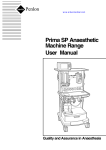
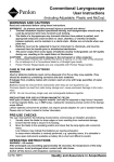
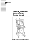
1
Sigma Delta Vaporizer
User Instruction Manual
This manual contains
calibration and service
records for Sigma Delta
Vaporizer, Serial No.
....................
Keep this manual with
the vaporizer at all times
Quality and Assurance in Anaesthesia
WARNING
Anaesthetic systems have the
capability to deliver mixtures of
gases and vapours to the patient
which could cause injury or
death unless controlled by a
qualified anaesthetist.
There can be considerable
variation in the effect of
anaesthetic drugs on individual
patients so that the setting and
observation of control levels on
the anaesthesia systems does
not in itself ensure total patient
safety.
Anaesthesia system monitors
and patient monitors are very
desirable
aids
for
the
anaesthetist but are not true
clinical
monitors
as
the
condition of the patient is also
dependent on his respiration
and the functioning of his
cardio-vascular system.
IT IS ESSENTIAL THAT THESE
ELEMENTS ARE MONITORED
FREQUENTLY AND REGULARLY
AND THAT ANY OBSERVATIONS
ARE
GIVEN
PRECEDENCE
OVER MACHINE CONTROL
PARAMETERS IN JUDGING THE
STATE
OF
A
CLINICAL
PROCEDURE.
IMPORTANT
For any enquiry regarding the
service or repair of this vaporizer,
contact the nearest accredited
Penlon agent* or contact the
Service Department at Penlon
Limited.
Servicing and Repairs
In order to ensure the full
operational life of the Sigma Delta
vaporizer, we recommend that a
periodic service check should be
performed by a Penlon trained
engineer. This check comprises a
vaporizer CALIBRATION CHECK
and LEAK CHECK.
Note:
(a) The calibration check must be
performed using a suitable agent
analyser,
e.g.
a
Riken
refractometer or infrared analyser.
(b) The service check is part of the
recommended pre-use check for
your Anaesthesia System.
*Agent's name and address:
Service and Repair Department
Penlon Ltd
Abingdon
OX14 3PH
UK
Tel:
+44 (0) 1235 547063
Fax:
+44 (0) 1235 547062
E-mail: [email protected]
Should the calibration check show
the unit to be outside the specified
performance requirement (see
section 11) then a service must be
performed.
This may be done on site by:
(a)
A trained user.
(b)
An authorised Penlon
agent.
(c)
A Penlon service engineer.
Always give as much of the
following information as possible:
1.
Type of equipment
2.
Product name
3.
Serial number
4.
Approximate date of
purchase
5.
Apparent fault
A calibration and service record
section is provided to maintain a
record
of
the
vaporizer's
performance.
(i)
FOREWORD
This manual has been produced to
provide authorised personnel with
information on the function, routine
performance and maintenance
checks, applicable to the Penlon
Sigma Delta vaporizer.
Information contained in the
manual is correct at the date of
publication. The policy of Penlon
Limited is one of continued
improvement to its products.
Because of this policy Penlon
Limited reserves the right to make
any changes, which may affect
instructions in this manual, without
giving prior notice.
Personnel must make themselves
familiar with the contents of this
manual before using the vaporizer.
Terminology
This manual complies with ISO
4135, Anaesthetic Apparatus
Terminology.
The following additional definitions
should be noted:
Vol.% - shortened form of
volumetric percentage.
The commonly used method of
expressing vapour concentrations
so that they can be compared with
concentrations of true gases.
100 Vol.% is equivalent to 100%
partial pressure in a mixture.
Copyright © Penlon Ltd, 2002.
All rights reserved.
(ii)
CONTENTS
1.
2.
USER RESPONSIBILITY
WARNINGS AND CAUTIONS
PURPOSE
1
2
7
3.
3.1
3.2
DESCRIPTION
Operating Principles
Controls
8
8
4.
4.1
4.2
4.3
4.4
4.5
4.6
4.7
4.8
4.9
SPECIFICATION
Physical Dimensions
Weight
Capacity
Filling System
Concentration Control Dial Scale
Patents
Temperature Range
Flow Range
Pressure Range
10
10
10
10
11
11
11
11
11
5.
5.1
5.2
5.3
FILLING AND DRAINING
Key Filler System
Screw Cap (Pour Fill) System
Quik-Fil Filling System
12
15
18
6.
6.1
6.2
6.3
6.4
6.5
6.6
6.7
INSTALLATION
Gas Port Transit Seals
Selectatec Compatible Models (with interlock)
Cagemount (23 mm) Taper Models
Penlon Off-line System (Mk.2 and Mk.3)
Drager 'Plug-in' Compatible
North American Drager Compatible
Pre-Use Checklist - All Models
21
21
23
24
25
26
27
7.
7.1
7.1.1
7.1.2
7.1.3
7.1.4
7.2
PERFORMANCE CHARACTERISTICS
Performance Graphs
Halothane Models
Enflurane Models
Isoflurane Models
Sevoflurane Models
Temperature Compensation
28
29
30
31
32
33
(iii)
CONTENTS
7.3
7.3.1
7.3.2
7.3.3
7.4
7.4.1
7.4.2
7.5
7.6
7.7
7.8
Pressure Effects
Ambient Pressure
Back Pressure
Intermittent Back Pressure
Summary of Performance Specifications
Factors Affecting Output Accuracy
Resistance to Gas Flow
Effect of IPPV on Output
Effect of Gas Composition on Output
Output when Control is at 0 (Zero)
Effect of Flush Valve Operation
33
33
33
33
34
34
35
35
35
35
36
8.
8.1
8.2
8.3
8.4
8.5
8.6
USER MAINTENANCE
Servicing
Cleaning
Draining - Halothane Models
Checking Vaporizer Output
Training Course
Returning the Vaporizer for Service or Repair
37
38
38
38
39
39
9.
REFERENCES
40
10.
ORDERING INFORMATION
41
11.
11.1
11.2
11.3
11.4
SERVICE RECORDS
Service Policy
Calibration Procedure using the Riken Analyser
Servicing and Repair Details
Calibration Check
42
43
46
50
(iv)
USER RESPONSIBILITY
This vaporizer has been built to
conform with the specification and
operating procedures stated in this
manual and/or accompanying
labels and notices when checked.
assembled, operated, maintained
and serviced in accordance with
these instructions provided.
To ensure the safety of this
vaporizer it must be checked and
serviced to at least the minimum
standards laid out in this manual.
A defective or suspected defective,
product must not, under any
circumstances be used.
malfunction which results from
improper use, maintenance, repair,
damage or alteration by anyone
other than Penlon Limited or its
appointed agents.
This vaporizer must only be
supplied to, and used by, suitably
qualified medical practitioners.
In the USA and Canada:
Caution: Federal Law restricts this
device to sale by or on the order of
a physician.
Statements in this manual
preceded by the following words
are of special significance.
The user must accept responsibility
for any malfunction which results
from non-compliance with the
servicing requirements detailed in
section 8.1.
WARNING - means there is a
possibility of personal injury to
yourself or others.
Worn, broken, d i s t o r t e d ,
contaminated
or
missing
components must be replaced
immediately. Should such a repair
become
necessary
it
is
recommended that a request for
service advice is made to the
nearest Penlon service centre.
CAUTION - means there is a
possibility of damage to the
instrument or other property.
NOTE - indicates points of
particular interest for more efficient
and convenient operation.
The reader must take particular
notice of the warnings, cautions.
and notes printed throughout the
manual.
This vaporizer and any of its
constituent parts must be repaired
only in accordance with written
instructions issued by Penlon
Limited, and must not be altered or
modified in any way without the
written approval of Penlon Limited.
The user of this equipment shall
have the responsibility for any
1
1.
WARNINGS AND CAUTIONS
The following Warnings and
Cautions must be read and
understood before using this
vaporizer
4
This vaporizer must not
be
modified
or
disassembled
by
an
unauthorised person. It
should
be
regularly
serviced by a Penlonauthorised service agent,
trained technician or
engineer and by no other
person.
(see section 8)
5.
Vaporizers
may
malfunction if exposed to
excessively
high
temperatures, e.g. by
storage above a radiator.
This may affect the
calibration.
WARNINGS
General Information
1.
2.
3.
The user must read and
be familiar with the
contents
of
this
instruction manual before
using the vaporizer
The vaporizer is designed
for use only with the
specific anaesthetic agent
named on the filler block
(and further indicated by
colour coded labelling).
Misdosage may occur if
the vaporizer is filled with
the wrong drug.
Agent specific (keyed)
filler devices are provided
on certain models to meet
national and international
standards.
(See
section
9
for
standards).
Maximum storage
temperature: 50oC (122oF)
Minimum storage
temperature: -20oC (-5oF)
Operating temperature
range:
15 to 35oC
(58 to 95oF)
Before use, function test
any vaporizer that has
been
subjected
to
temperatures near the
upper/lower limits given
above.
The pharmacopoeia name
of the drug is used on the
label according to BP,
USP, or Ph EUR.
The user is responsible
for confirming that any
trade name of a drug is
equivalent
to
the
registered name.
2
WARNINGS AND CAUTIONS
the patient during the
filling procedure.
Filling and draining the
vaporizer
6.
The filler system must be
maintained in accordance
with the instructions
given
in
the
User
Maintenance section.
7.
The vaporizer must be
filled only by suitably
skilled
and
trained
personnel.
8.
Anaesthetic drugs are
poisonous and there is
evidence that there is a
health
hazard
to
personnel
due
to
prolonged inhalation of
trace concentration in the
atmosphere. Care must
be taken to avoid spillage
of anaesthetic drugs
when filling or draining
vaporizers.
9.
The vaporizer control
must be in the 0 (zero)
position during the filling
or draining process.
Overfilling and/or spilling
may occur if the control is
not in the 0 (zero)
position.
Provided the control is in
the 0 (zero) position, gas
may continue to be
delivered
from
the
anaesthetic machine to
3
10.
The vaporizer must be
upright during filling to
minimise the risk of
overfilling.
11.
Do
not
use
the
anaesthetic agent bottle
to fill the vaporizer if the
bottle is cracked or the
filler connector is loose or
broken.
This may result in
overfilling
or
contaminated
agent
entering the vaporizer.
12.
If a new bottle of
anaesthetic agent is to be
used, check that the
tamper-evident
shrink
band is undamaged.
13.
Ensure that the drain plug
screw, located on the
lower
front
of
the
vaporizer, is correctly
tightened to prevent loss
of liquid agent.
14.
Do not tamper with the
filling system valve. This
may cause a vapour and
fresh gas leak.
Anaesthesia
system
monitors and patient
monitors
are
very
desirable aids for the
WARNINGS AND CAUTIONS
anaesthetist but are not
true clinical monitors as
the condition of the
patient is also dependent
on his respiration and the
functioning
of
his
cardiovascular system.
15.
the clamp screw before
using the vaporizer. The
vaporizer will leak if this
is not done.
Quik-Fil models - remove
the bottle and refit the
filler block cap before
using the vaporizer.
Do not overfill.
A vaporizer that has been
overfilled
must
be
withdrawn from use.
Delivered concentrations
are inaccurate while the
filler port is open.
Contact
the
Service
Department at Penlon for
advice.
16.
17.
Before using the vaporizer
Anaesthetic drugs must
be
treated
as
a
pharmaceutical product.
Liquid should never be
drained from a vaporizer
into an open container
and
then
reused.
Contamination is likely.
Always dispose of such
drained liquid as a
hazardous chemical.
After filling or draining:
Pour Fill (Screw cap) filler
always
refit
and
retighten the filler cap.
Key (agent specific) filler
models - always tighten
the filler control.
In addition, on key filler
systems, always refit the
key filler plug and tighten
18.
Do not use the vaporizer if
the agent level is not
visible in the sight glass
or the level is outside of
the Max - Min indicator.
19.
If
a
vaporizer
is
transported when filled
with liquid drug the
control must be in the 0
(zero) position during
transport and a period of
at least ten minutes in a
secured upright position
must
elapse
before
connection
to
an
anaesthetic
breathing
system.
Movement
during
transport can result in
over-dosage unless time
is allowed for drainage of
liquid to the normal
4
WARNINGS AND CAUTIONS
position.
If a vaporizer has been
transported with the
control in the open
position it must be
flushed at 5 L/min for ten
minutes before clinical
use on a patient
20.
selectatec manifold and
the rear frame panelling
of the machine to allow
the vaporizer connector
block to seal correctly on
the manifold.
23.
The vaporizer must not be
tipped over or inverted.
If the vaporizer has been
tipped over or inverted it
must be set to maximum
output and flushed at 5 L/
min for ten minutes
before clinical use on a
patient.
21.
22.
Before use test all joints
for gas tightness, and
perform back bar function
tests as detailed in the
anaesthetic machine user
manual.
Using the vaporizer
The vaporizer must be
securely fixed and in an
upright position before
connection to a patient.
There is a danger of
overdosage if sudden
inadvertent
movement
occurs during use.
Anaesthetic
machine
designs are constantly
evolving, and new models
may differ dimensionally
from existing equipment.
It
is
the
user's
responsibility to ensure
that the configuration of
the anaesthetic machine
allows correct installation
of the vaporizer.
There must be sufficient
clearance between the
24.
Check the liquid level
frequently when using the
vaporizer and maintain
the level between the min.
and max. marks.
The vaporizer control
must be in the zero (0)
position during the filling
process (see warning 7).
25.
Vaporizer outputs are
sensitive to barometric
pressure.
A correction factor may
be
necessary
when
assessing the output
using an analyser, for
example at high altitude.
Barometric
pressure
effects are not usually of
clinical importance. (see
section 7.3).
5
WARNINGS AND CAUTIONS
CAUTIONS
26.
The vaporizer is a flow
direction-sensitive apparatus
and the direction of gas flow
towards the patient must be
as indicated by the arrow on
the top label.
Reversal of flow may cause
inaccuracies of delivered
concentration.
27.
The vaporizer must not be
used downstream of the
common gas outlet.
28.
As stated in section 2, the
vaporizer is of relatively high
resistance and must not be
incorporated within a
breathing system.
29.
Expired anaesthetic vapours
should be extracted from the
theatre by an anaesthetic
gas scavenging system.
(see section 9 for
standards.)
30.
Do not use the vaporizer
with flammable anaesthetics.
User Maintenance
31.
Do not pour water, or any
cleaning solutions into the
vaporizer.
6
1
Anaesthetic machine and
workstation
standards
require that means be
provided to ensure that gas
cannot pass through more
than
one
vaporizer
chamber.
Vaporizers without interlock
devices or systems must
only be used on machines
which only have one
vaporizer mounting station.
2.
PURPOSE
The Sigma Delta vaporizer is
designed for incorporation in the
fresh gas supply system of
continuous
flow
anaesthetic
machines, directly connected
between the flowmeter unit and the
common gas outlet of the machine.
The vaporizer is unsuitable for use
within a breathing system 'in circuit'
because of the relatively high
internal resistance.
Its purpose is the provision of
accurate
concentrations
of
anaesthetic drugs in the fresh gas
supply, in accordance with the
setting of the control dial, when the
fresh gas supply flow is between
0.2 and 15 litres/min.
Refer to section 7 (Performance
Characteristics), which shows the
extent of modifications to the
control calibration.
7
3.
DESCRIPTION
3.1 Operating
Principles
Each model is uniquely designed
and tested for use only with the
drug specified on the filler block.
2
3
The vaporizer contains a chamber,
the base of which holds the anaesthetic agent in liquid form. A wick
ensures that the upper part of the
chamber is filled with the saturated
vapour of the agent. The wick has
a patented construction.
The concentration of saturated
vapour is many times higher than
those used clinically and the function of the concentration control is
to proportion the flow of the carrier
gas through a bypass passage and
through the vapour chamber so
that the desired dilution is produced.
In the zero position the bypass
remains open but the vaporizing
chamber is shut off completely
from the gas flow to the patient.
1
1.
2.
3.
Liquid level indicator
Control dial 0 (zero) position
Interlock bolt
3.2 Controls
The vaporizer has a single, forward
facing calibrated control to regulate
the vapour concentration delivered.
The dial is locked at zero when not
in use. To set a concentration level,
push the dial assembly in and
rotate anti-clockwise.
A temperature-compensating valve
is situated in the bypass, arranged
to operate so that as the vapour
pressure varies with temperature.
the dilution ratio produced by the
control valve is varied to compensate. and maintain a constant output concentration.
Align the required concentration
graduation with the mark at the top
of the bezel.
On returning the dial to zero, the
dial assembly will automatically
spring outwards into the locked 'off'
position.
The vaporizer has a liquid level
indicator, with maximum and minimum level marks.
8
Interlock Models
When the vaporizer is mounted on
the anaesthetic machine back bar
with other interlock vaporizers, initial operation of the concentration
control dial activates the interlock
system ensuring that only one of
the vaporizers con be in use at any
time.
The interlock deactivates as soon
as the control dial is returned to the
locked out zero position.
NOTE
The Sigma Delta Selectatec
Compatible
Vaporizer
with
Interlock can be used on a
Selectatec
Universal
Series
Manifold back bar in conjunction
with other types of Selectatec compatible vaporizers (i.e. from other
manufacturers) fitted with the interlock function.
WARNING
The Drager compatible model
with interlock must only be used
with other Drager-compatible
interlock vaporizers, to maintain
the integrity of the interlock system.
9
4.
SPECIFICATION
4.1
Physical Dimensions
Cagemount
Selectatec Compatible with Interlock
Drager 'plug in' Compatible
Width
Height
Depth
133
120
100
219
242
242
158
190
190
Dimensions given above are in millimetres
NOTE
For Screw Cap Filler models depth, subtract 11 mm from the depth dimensions given above.
4.2
Weight
Approximate weight: 4.8 kg.
4.3
Capacity
Volume at MAX mark
250 ml (nominal)
Volume at MIN mark
35 ml (nominal)
NOTE
After draining, approximately 60 ± 10 mI of liquid is retained by the wick.
4.4
Filling System
Key Filler (Agent Specific)
Used with corresponding agent specific filler adaptor, see section 10,
Ordering Information.
Pour Fill (Screw Top)
Quik Fil - Sevoflurane only
Use with corresponding agent specific bottle.
10
SPECIFICATION
4.5
Control Dial Scale
The control dial is marked as follows:
From 0 to 2% vol, by intervals of 0.2% vol
From 2 to maximum, by intervals of 0.5% vol
The control dial is marked '0' at zero
4.6
Patents
The Sigma Delta is protected by UK and foreign patents.
4.7
Temperature Range
Storage Temperature Range
15 to 35oC (58 to 95oF)
-20 to 50oC (-5 to 122oF)
Storage in Transit (up to 7 days)
-40 to 60oC (-40 to 149oF)
Operating Temperature Range
4.8
Flow Range
Operating Flow Range
0.2 to 15 litres/min.
See section 7.4.1 for output accuracies at extreme conditions.
4.9
Pressure Range
Operating Pressure Range
Maximum Manifold Pressure
Maximum Test Pressure
0 to 5 kPa (0 to 0.7 psi)
38 kPa (5.5 psi)
38 kPa (5.5 psi)
11
5.
FILLING AND DRAINING
5.1 Key Filler System
WARNING
The vaporizer must be either
secured to the anaesthetic
machine or free standing on a
level table so that in either case
it is upright during the filling
process.
Overfilling may occur if the
vaporizer is tipped during the
filling process.
WARNING
The vaporizer concentration
control must be in the 0 (zero)
position during the filling
process. Provided this is done,
gas may continue to be delivered from the anaesthetic
machine to a patient during the
filling process.
WARNING
Check that the drug name on the
vaporizer and the supply bottle
are the same before commencing the filling process, and
ensure that the bottle is fitted
with a keyed collar.
1
2
3
NOTE
Penlon supply a complete range of
agent specific filler adaptors, see
section 10.
Filling the Vaporizer
This system is manufactured in
compliance with ISO 5360.
1.
2.
3.
Tighten the adaptor to
ensure an airtight joint,
which must be maintained
throughout the filling operation.
WARNING
Failure to observe this instruction may result in overfilling.
Check that the vaporizer
concentration control (1) is
in the 0 (zero) position as
illustrated.
Attach the keyed filler adaptor (2) to the bottle (3).
12
FILLING AND DRAINING
4.
Loosen the clamp screw (4).
Remove the plug (5).
5.
Insert the keyed end of the bottle
adaptor (2) fully into the vaporizer
receiver.
Only the correct keyed-adaptor can
enter the receiver.
Tighten the clamp screw (4) to
secure the adaptor.
6.
5
6
Raise the bottle above the filler
(see arrow on the illustration).
7.
Open the filler control (6) - lift
upwards.
Allow the liquid to flow into the
vaporizer until the upper mark is
reached on the filler block (7).
WARNING
DO NOT OVERFILL.
A vaporizer that has been overfilled
must be withdrawn from use.
If the vaporizer has been inadvertently
overfilled, excess liquid agent will spill
from the drain hole in the keyed slot in the
filler block. DO NOT REUSE THIS AGENT
Allow all the excess liquid to drain from the
vaporizer before inserting the plug (5).
8.
9.
4
Close the filler control (6).
Lower the bottle below the level of
the filler and allow the liquid in the
bottle adaptor to flow back into the
bottle.
Loosen the clamp screw (4),
remove the bottle adaptor from the
receiver.
NOTE
A small amount of liquid is always likely to
spill when the bottle adaptor is removed
from the receiver.
13
7
2
6
4
FILLING AND DRAINING
10.
Insert the plug (5) and tighten
the clamp screw (4).
WARNING
For the vaporizer to function correctly it is important to insert the
sealing plug (5) fully, until it stops,
before clamping it into position with
the clamp screw (4) after filling is
completed.
If this is not done, the possibility
exists that agent may leak from the
vaporizer or the vaporizer may not
pressurise properly, giving reduced
concentration output and gas flow
to the patient.
14
4
5
FILLING AND DRAINING
WARNING
Anaesthetic drugs must be treated as a pharmaceutical product.
Liquid should never be drained
from a vaporizer into an open
container and reused.
Contamination is likely. Always
dispose of such drained liquid
as a hazardous chemical.
Draining the Vaporizer
CAUTION
To reduce atmospheric pollution in
the operating room, it is recommended that vaporizer drainage
should be performed in a fume
cupboard or under an extractor
hood.
WARNING
The vaporizer must be either
secured to the anaesthetic
machine or free standing on a
level table so that in either case
it is upright during the draining
process.
WARNING
The vaporizer concentration
control must be in the 0 (zero)
position during the draining
process
1.
Check that the vaporizer
concentration control (1) is
in the 0 (zero) position.
2.
Follow steps 2 to 5 of
procedure for filling
vaporizer (see above),
keep the bottle below
filler.
3.
Raise the the filler control
(2) and allow the liquid to
run into the bottle until the
flow ceases.
4.
1
2
the
the
but
the
3
4
Close the filler control (2),
loosen the clamp screw (3),
and reinsert the plug (4).
Tighten the clamp screw
(3).
15
FILLING AND DRAINING
3.
Remove the bottle cap and
fill the vaporizer slowly and
carefully, stopping to check
the liquid level occasionally.
Stop filling when the upper
mark is reached on the filler
block.
WARNING
DO NOT OVERFILL.
A vaporizer that has been overfilled must be withdrawn from
use.
5.2 Screw Cap Filling
System (Pour Fill)
CAUTION
To minimise atmospheric pollution
in the operating room, fill the vaporizer in a fume cupboard or under
an extractor hood.
WARNING
The vaporizer must be either
secured to the anaesthetic
machine or free standing on a
level table so that in either case
it is upright during the filling
process.
Overfilling may occur if the
vaporizer is tipped during the
filling process.
WARNING
The vaporizer control must be in
the 0 (zero) position during the
filling process.
Provided this is done, gas may
continue to be delivered from
the anaesthetic machine during
the filling process.
WARNING
Check the drug name on the
vaporizer and the supply bottle
before commencing the filling
process.
4.
Replace the filler cap after a
visual check that the seal is
in position on the cap.
Tighten finger tight only. DO
NOT use a wrench.
WARNING
Do not operate the vaporizer if
the filler cap is not secured in
position.
Incorrect concentration may be
delivered to the patient and pollution may result.
2
Filling the Vaporizer
If the vaporizer is empty, check
that the control screw (1) is fully
tightened before filling
1.
Check
that the vaporizer concentration control (2)
is in the 0 (zero) position as
illustrated.
2.
Unscrew the filler cap (3).
3
16
1
FILLING AND DRAINING
container and reused.
Contamination is likely. Always
dispose of such drained liquid
as a hazardous chemical.
Draining the Vaporizer
CAUTION
To minimise atmospheric pollution
in the operating room, perform
vaporizer drainage in a fume cupboard or under an extractor hood.
4.
WARNING
The vaporizer must be either
secured to the anaesthetic
machine or free standing on a
level table, so that in either case
it is upright during the draining
process.
Allow the liquid to run into
the bottle until the flow
ceases
Close the drain screw (3).
CAUTION
Always close the drain screw firmly
before replacing the filler cap on
the vaporizer.
WARNING
The vaporizer concentration
control must be in the 0 (zero)
position during the draining
process.
1.
Check
that the vaporizer concentration control (1)
is in the 0 (zero) position, as
illustrated.
2.
Unscrew the filler cap (2).
3.
Place a bottle marked with
the drug name on the
vaporizer under the drain
tube in the base of the filler
block and undo the drain
screw (3) at least three full
turns.
1
2
3
WARNING
Anaesthetic drugs must be treated as a pharmaceutical product.
Liquid should never be drained
from a vaporizer into an open
17
FILLING AND DRAINING
5.3
in the User Maintenance
section.
Quik-Fil System
WARNINGS
1.
Do not use the anaesthetic
agent bottle to fill the
vaporizer if the bottle is
cracked or the filler connector is loose or broken.
This may result in overfilling or contaminated agent
entering the vaporizer.
2.
If a new bottle of anaesthetic agent is to be used,
check that the tamper-evident shrink band is undamaged.
3.
Firmly secure the vaporizer
in a vertical position before
filling.
4.
Ensure that the drain plug
screw, located on the lower
front of the vaporizer, is
correctly tightened to prevent loss of liquid agent.
5.
Do not tamper with the filling system valve. This may
cause a vapour and fresh
gas leak.
6.
The filler system must be
maintained in accordance
with the instructions given
18
7.
The vaporizer must be
filled only by suitably
skilled and trained personnel.
8.
After filling, remove the
bottle and refit the filler
block cap before using the
vaporizer.
9.
Do not use the vaporizer if
the agent level is not visible in the sight glass or the
level is outside of the
Max - Min indicators.
FILLING AND DRAINING
Quik-Fil System - Filling
the Vaporizer
1.
2.
3.
4.
5.
6.
Check that the vaporizer
concentration control is in the
off ('0') position.
Remove the yellow protective
cap from the anaesthetic agent
bottle filler, checking that the
bottle and filler mechanism are
not damaged.
Remove the vaporizer filler
block cap and insert the bottle
nozzle into the filler block,
Rotate the bottle to align the
bottle filler keys with the slots in
the filler block.
Note the liquid level in the
vaporizer sight glass and press
the agent bottle firmly into the
vaporizer filler against the
spring valve assembly.
Allow the liquid to flow into the
vaporizer until the maximum
level mark is reached, paying
continuous attention to the level
in the sight glass and the air
return bubbles flowing into the
bottle.
Release the bottle when the
vaporizer is full and the
continuous stream of bubbles
ceases.
Withdraw the bottle from the
vaporizer filler and replace the
vaporizer filler block cap and
the yellow cap on the agent
bottle.
WARNING
The filler cap must be refitted
before using the vaporizer.
19
FILLING AND DRAINING
Quik-Fil System - Draining
the vaporizer
WARNING
To avoid spillage, check that the
bottle to be used for draining has
sufficient capacity for the volume
of liquid to be drained.
1.
Remove the yellow protective
cap from an empty sevoflurane
bottle. Insert the bottle nozzle
into the drain funnel.
Rotate the bottle to align the
bottle filler keys with the index
slots in the drain funnel, and
screw the drain funnel onto the
empty bottle.
2.
Remove the vaporizer filler
block cap.
3.
Fully insert the drain funnel into
the keyed drain slot, and
unscrew the drain plug.
Continue to drain the vaporizer
until empty.
Close the drain plug and tighten, and withdraw the drain funnel.
4.
Unscrew the drain funnel from
the bottle and refit the bottle
cap and the vaporizer filler
block cap.
WARNING
The filler cap must be refitted before
using the vaporizer.
WARNING
Do not reuse the agent drained from
the vaporizer. Treat as a hazardous
chemical.
20
6.
INSTALLATION
6.1 Gas Port Transit
Seals
All vaporizers
CAUTION
Inlet and outlet ports are sealed for
delivery transit. Ensure that these
seals are removed from the
vaporizer before installation on an
anaesthetic machine.
6.2 Selectatec
Compatible Models
- with Interlock
1
These vaporizers are designed for
installation on a Selectatec
Universal Series type manifold
back bar and can also be used on
the Type 3 Manifold.
2
2
NOTE
When installing two vaporizers only
on a three station manifold, the
centre station must be occupied by
one of the vaporizers.
3
WARNING
Anaesthetic machine designs
are constantly evolving, and new
models may differ dimensionally
from existing equipment
1.
2.
3.
It is the user's responsibility to
ensure that the configuration of the
anaesthetic machine allows correct
installation of the vaporizer.
There must be sufficient clearance
between the Selectatec manifold
Locking Lever
Interlock Bolts
Back Bar Manifold Locking Shaft
and the rear panelling/frame of the
machine to allow the vaporizer
connector block to seal correctly on
the manifold.
21
INSTALLATION
Installation
1.
2.
3.
4.
Removal
Carefully offer the vaporizer
up to the manifold.
Align the gas connection
ports with the valve capsule
on the manifold. (The capsule is referred to as the
valve ‘cartridge' in some
user literature)
Carefully lower the vaporizer onto the manifold, and
recheck that the gas ports
are correctly engaged with
the valve capsule cartridges
on the manifold.
Lock into position by pushing the locking lever downwards and rotating clockwise through 90o.
NOTE
The concentration control dials of
all the vaporizers linked by the
interlock system must be turned to
zero before removing the vaporizer
from the manifold.
To remove the vaporizer, rotate the
locking lever 90o anti-clockwise
and carefully lift the unit vertically
until clear of the back bar.
CAUTION
To prevent damage to the locking
shaft, recheck that the gas ports
are correctly engaged with the
valve capsule cartridges on the
vaporizer before tightening the
locking lever.
Pre-use Checks
Observe the WARNING below and
carry out the check list procedure
given in section 6.7.
WARNING
Test all joints for gas tightness
before using the anaesthetic
machine.
The locking lever MUST be in the
locked position before the vaporizer is operated.
22
INSTALLATION
6.3 Cagemount (23 mm)
Taper Models
4
2
CAUTION
It is recommended that this type of
vaporizer should only be used on
machines with a single vaporizer
mounting station.
1
Vaporizers fitted with cagemount
tapers have the male taper (1) (Inlet
port) on the left and the female taper
(2) on the right (viewing the front of
the vaporizer).
Two M6 studs with nuts, washers
and a clamp plate (3) are provided
to fix the vaporizer to the back of the
anaesthetic machine, or Modura
claw assembly.
3
Taper Connectors
It is essential that the taper cone
joints should be engaged axially and
not sideways loaded.
1.
Adjust the distance from the
back bar to the taper joint by
adding or removing the
shims (4) .
2.
The cone joints should be
lightly smeared with an oxygen compatible lubricant
such as Fomblin.
3.
Engage the taper joints by
applying axial pressure.
4.
Tighten the fixing nuts (3).
23
INSTALLATION
4.
3
Attach the vaporizer to the
Modura
rail
on
the
anaesthetic machine and
secure in place by moving
the lever into its 'locked on'
position.
Pre-use Check
Observe the WARNING below and
carry out the check list procedure
given in section 6.7.
WARNING
Test the joints for gas tightness
before using the machine.
2
1
6.4 Penlon Off-line
Mounting System
Installation on Modura Rail
WARNING
The vaporizer must not be tipped
or inverted during installation.
If the vaporizer has been tipped
or inverted, it must be set to
maximum and flushed at 5 L/min
for ten minutes. Check for stable
output before clinical use.
1.
2.
3.
A vaporizer with cagemount tapers
may be fitted with a Penlon clip,
Part No. 58090, in place of the
back bar clamp. The vaporizer may
then be fitted to a Penlon off-line
block, (use Penlon Part No. 52280
for the Mk.2 and Part No, 52270 for
the Mk.3 system).
The flexible hoses attached to the
block are connected to the inlet
and outlet of the vaporizer.
Remove the M6 nuts and
washers, the clamp plate and
the shims from the vaporizer.
Fit the Modura claw (1) to the
backplate (2), using the two
M6 screws.
Fit
the
Modura
claw
backplate assembly to the
studs (3) on the rear of the
vaporizer, and secure with
the M6 nuts and washers.
It is recommended that detachable
cagemount
connectors
are
retained with Safety Clip (Part
Number 52275), to prevent
inadvertent disconnection,
WARNING
Test the joints for gas tightness
before using the machine.
24
INSTALLATION
6.5
Drager 'Plug-in'
Compatible (interlock)
Installation
1
NOTE
When installing two vaporizers only
on a three station manifold, the
centre station must be occupied by
one of the vaporizers.
1.
Carefully offer the vaporizer
up to the manifold.
2.
Align the gas connection
ports with the valve capsule
on the manifold. (The
capsule is referred to as the
valve ‘cartridge' in some
user literature)
3.
Carefully
lower
the
vaporizer onto the manifold,
and recheck that the gas
ports are correctly engaged
with the valve capsule
cartridges on the manifold.
4.
Lock into position by
pushing the locking lever (1)
downwards and rotating
clockwise
through
o.
approximately 100
2
3
1.
2.
3.
Locking Lever
Interlock Bolts
Back Bar Manifold Locking Shaft
that the vaporizer is firmly
positioned on the manifold before
tightening the locking lever.
The locking lever MUST be in the
locked
position
before
the
vaporizer is used.
Pre-use Checks
Observe the WARNINGS below
and carry out the check list
procedure given in section 6.7.
WARNING
To prevent damage to the
locking shaft (3), and to ensure
that the gas connection ports
are correctly engaged, check
Removing the Vaporizer
Rotate the locking lever fully
anticlockwise and carefully lift the
vaporizer from the manifold.
25
INSTALLATION
6.6 North American
Drager Compatible
(Interlock)
Installation
1.
2.
3.
Check that each gas port (1) is
fitted with the correct O seal,
as supplied by the anaesthetic
machine manufacturer (Drager
part No. M21929).
Carefully offer the vaporizer up
to the manifold.
To secure the vaporizer to the
manifold, use two M4 x 30
screws (DIN 912 Property
Class 8.8) and fan-type lock
washers, as supplied with the
machine.
From the rear of the
anaesthetic machine fit the
two screws through the
manifold block holes (2), and
screw into the threaded holes
in the vaporizer.
Tighten the screws to a torque
of 2.7 to 3.0 Nm.
Pre-use Checks
Carry out the check list procedure
given in section 6.7.
Removing the Vaporizer
1.
2.
3.
Support the vaporizer, and
remove the securing screws.
Detach the vaporizer from the
manifold.
Check that the O-seals are
retained in the gas ports (1).
26
1
2
2
1
INSTALLATION
6.7 Pre-Use Check List
In addition to the pre-use warnings
listed for different models in sections 6.2 to 6.6 the following check
list procedure must be carried out
on ALL vaporizers before use.
1.
2.
3.
4.
5.
Check that the vaporizer
concentration control is in
the 0 (zero) position.
Check that the liquid level is
between the upper and
lower marks on the filler
block.
On key fill (agent specific
filler) models, check that the
filler plug is fully inserted
and that the clamp screw is
fully tightened.
On pour fill (screw cap filler)
models, check that the filler
cap is securely closed.
Perform a back bar manifold leak test as detailed in
the relevant anaesthetic
machine user instruction
manual.
WARNING
Anaesthetic machine designs
are constantly evolving and new
models may differ dimensionally
from existing equipment.
It is the user's responsibility to
ensure that the configuration of the
anaesthetic machine allows correct
installation of the vaporizer.
27
7. PERFORMANCE CHARACTERISTICS
NOTE
Concentration output figures quoted and
shown graphically in this section were compiled
from average test results from a number of
vaporizers.
The output from individual units may vary from
these average figures.
28
PERFORMANCE CHARACTERISTICS
7.1
Performance Graphs
7.1.1
Halothane
Variation of output with flow rate (Temperature: 20oC)
6
Output Vol%
5
5% set
4
4% set
3
2
2% set
1
1% set
0.6% set
0.2% set
0
0.2 1
2
3
4
5
6
7
8 9 10 11 12 13 14 15
Flow rate L/min
Variation of output with temperature (Flow rate: 5 L/min)
6
5
Output Vol%
5% set
4
4% set
3
2
2% set
1
1% set
0.6% set
0.2% set
0
10
15
20
25
Temperature oC
29
30
35
PERFORMANCE CHARACTERISTICS
7.1.2
Enflurane Models
Variation of output with flow rate (Temperature: 20oC)
6
5
4
4% set
3
2
2% set
1
1% set
0.6% set
0.2% set
0
0.2 1
2
3
4
5
6
7
8 9 10 11 12 13 14 15
Flow rate L/min
Variation of output with temperature (Flow rate: 5 L/min)
6
Output Vol%
Output Vol%
5% set
5
5% set
4
4% set
3
2
2% set
1
1% set
0.6% set
0.2% set
0
10
15
20
25
Temperature oC
30
30
35
PERFORMANCE CHARACTERISTICS
7.1.3
Isoflurane Models
Variation of output with flow rate (Temperature: 20oC)
Output Vol%
6
5
5% set
4
4% set
3
2
2% set
1
1% set
0.6% set
0.2% set
0
0.2 1
6
2
3
4
5
6
7
8 9 10 11 12 13 14 15
Flow rate L/min
Variation of output with temperature (Flow rate: 5 L/min)
Output Vol%
5
5% set
4
4% set
3
2
2% set
1
1% set
0.6% set
0.2% set
0
10
15
20
25
Temperature oC
31
30
35
PERFORMANCE CHARACTERISTICS
7.1.4
Sevoflurane Models
Variation of output with flow rate (Temperature: 20oC)
9
8
Output Vol%
7
8% set
7% set
6% set
6
5
5% set
4
4% set
3
3% set
2
2% set
1
1% set
0.6% set
0.2% set
0
0.2 1
2
3
4
5
6
7
8
9
10 11
12 13 14 15
Flow rate L/min
Variation of output with temperature (Flow rate: 5 L/min)
8
8% set
Output Vol%
7
6
5
6% set
5% set
4
4% set
3
2
2% set
1
1% set
0.6% set
0.2% set
0
10
15
20
25
30
Temperature oC
32
35
PERFORMANCE CHARACTERISTICS
7.2 Temperature
Compensation
C is delivered concentration vol%,
S% is the set value.
Temperature compensation is provided by the operation of a variable
resistance valve in the bypass passage. The design provides compensation for the full range of user
temperatures. If the vaporizer is
used in extreme temperatures,
(outside those shown in section
4.7) outputs may be lower or higher than indicated by the concentration control.
NOTE
The temperature compensator
reacts relatively slowly to room
temperature changes.
If the temperature around the
vaporizer is suddenly changed
(e.g. by wheeling an anaesthetic
machine from a cool store into theatre), 1 to 2 hours minimum should
be allowed for it to equalise with
the ambient temperature before
use.
Changes in barometric pressure
can be ignored clinically because
they affect the vaporization in the
vaporizer and the absorption of
vapour through the lungs in the
some way. They must be corrected
for when checking outputs with an
analyser.
NOTE
Some analysers include automatic
barometric pressure correction.
Check the instructions provided
with the analyser.
7.3
Pressure Effects
7.3.1
Ambient Pressure
7.3.2 Back Pressure
Back pressures imposed on the
vaporizer by ventilators or other
parts of the anaesthetic apparatus
are usually relatively small, but certain ventilators can impose steady
back pressures of 10 to 15 kPa
(100 to 150 cmH2O) which will produce a reduction of the output concentration.
7.3.3 Intermittent Back
Pressure
Ambient pressure effects are not
normally of clinical significance but
the following rules apply:
The control is graduated in units of
vol% at 101.3 kPa (14.7 psi). At
any other pressure the true output
will be modified according to the
equation:
C = S% x 101.3
P
Intermittent back pressure imposed
on the vaporizer by a ventilator
may result in some change in output. The effect is greatest at low
settings of the control and low flow
rates, and the Sigma Delta vaporizer is designed to comply with the
tests laid down in various
Standards in this respect (see section 9).
P is absolute pressure in kPa.
33
PERFORMANCE CHARACTERISTICS
7.4 Summary of Performance
Specifications
7.4.1 Factors Affecting
Accuracy
Output
The following conditions may affect the accuracy of the vaporizer.
Column A in the table shown below lists the
design limits for normal use.
Column B lists extreme conditions, and, if necessary, indicates when the vaporizer may be
used reliably only after reference to the sections of the manual indicated.
Under the conditions listed in column A, the
maximum deviation from the set concentration
is ±20% of scale reading or ±5% of the maximum graduation, whichever is greater.
A (Normal Use)
B (Extreme Conditions)
Gas composition
O2, Air + N2O mixture
Helium mixture, section 7.6
Liquid level
See section 1, WARNING 18
Temperature
Liquid visible between
MIN and MAX marks
15 to 35oC
Flow Rate
0.5 to 10 L/min
0.2 to 0.5 and 10 to 15 L/min
Accuracy not affected.
Altitude
Sea level to 2440 m
(8000 ft)
Very high altitudes*
or hyperbaric conditions*
Intermittent back
pressure
Movement
As Standards listed in
section 9 (a)
Do not agitate during use
See section 1, WARNING 21
Inversion or tipping
Do not tip or invert
10 to 15oC and 35 to 40oC,
section 7.2
Flush for 10 minutes at
5 L/min before use.
See section 1, WARNING 20
*The combination of high altitude and high temperature may lead to loss of accuracy.
34
PERFORMANCE CHARACTERISTICS
7.4.2. Resistance to Gas
Flow
7.6 Effect of Gas
Composition on
Output
Resistance to gas flow, measured
at:
22oC (72oF)
The vaporizer is calibrated with
pure oxygen and the scale is therefore most accurate with this gas.
The effect of other gases normally
used in anaesthesia is as follows:
101.3 kPa (1013 mbar, or 14.7 psi),
Control position 0 (zero)
Flow Rate Resistance
using Air
(cmH2O)
(L/min)
1
2
4
8
Nitrous oxide
Nitrous oxide, added to oxygen, will
produce a decrease in output
below the scale value. At a concentration of 70% nitrous oxide output may decrease by up to 15%.
1.8
3.4
8.0
20.3
Resistance varies from these nominal values at other control positions, with changes with temperature, and for each agent (e.g. the
nominal value for Sevoflurane at 4
L/min (air) is 12 cmH2O).
Carbon dioxide
Carbon dioxide is not usually
added in high concentrations and is
usually limited to 5%. At this concentration the effect on vaporizer
output is negligible.
7.5 Effect of IPPV on
Output
Air
For 2 kPa IPPV at a flow rate
L/min, output concentration
vary by up to 20%,
For 5 kPa IPPV at a flow rate
L/min, output concentration
vary by up to 10%.
Helium
Air will reduce the output of the
vaporizer below the scale values
by a maximum of 5%.
of 2
will
of 8
will
Vaporizers will give low results on
helium-enriched mixtures, and the
use of an analyser is recommended if accurate concentrations are
required when using this gas.
35
PERFORMANCE CHARACTERISTICS
7.7 Output when
Control is at 0
(zero)
Output vapour concentration when
the control is at 0 (zero) is less than
0.03% vol., when tested in accordance with ASTM 1161-88.
7.8 Effect of Flush
Valve Operation
Operating the flush valve on the
anaesthetic machine will affect output concentration by less than
±20%.
Note that the vaporizer was tested
to ISO 8835.1 / IEC 60601-2-13.
36
8.
USER MAINTENANCE
CAUTION
Do not attempt to dismantle the
vaporizer or make any adjustment
to it which is outside the scope of
the following instructions.
8.1
(b)
Servicing
(c)
NOTE
A label is fixed across the vaporizer body and top cover, bearing the
words:
(d)
GENUINE PART.
LABEL TAMPERING
VOIDS WARRANTY.
When the bottom cover of the
vaporizer is removed this label will
be damaged beyond repair as permanent evidence of unauthorised
servicing, repair or modification.
If this label (or other labels) is missing, do not use the vaporizer until it
has been serviced (see below).
(e)
(d)
The Sigma Delta must only be
serviced at an authorised service
centre or by Penlon-trained technicians in accordance with the following procedure.
(a)
Successive sets of figures
should be compared to determine if performance is deteriorating.
Should deterioration be detected, a service
should be carried out to
restore normal operation.
A major overhaul must be
performed every ten years
(Halothane models - 5 years)
to maintain performance
within the specification.
The Selectatec compatible
vaporizer locking system
should be inspected during
the vaporizer calibration test,
and if damage to the locking
shaft is suspected, the device
must be referred to a Penlon
certified engineer,
Interlock system vaporizers function test the interlock system during the vaporizer calibration test.
Quik-Fil system - at regular
intervals (3 monthly minimum, 6 monthly maximum),
filling and draining must be
checked under controlled
conditions
NOTE
The user must accept responsibility for any malfunction which results
from non-compliance with the
above requirements.
The calibration should be
checked periodically under
controlled conditions (section
8.4) and leak tests performed.
Record the measured values
in section 11.
37
USER MAINTENANCE
If the vaporizer is in regular use this
draining operation should be
performed weekly.
WARNING
Prolonged
exposure
of
anaesthetic agents to light and
gases may lead to a brown or
yellow colouration.
8.2 Cleaning and
Sterilisation
WARNING
Do not pour water, or any
cleaning solutions into the
vaporizer.
The process of filling and emptying
will clean the internal passageways
of the vaporizer filler block
satisfactorily.
The exterior of the vaporizer should
be kept clean and dust free with a
dry cloth, or, if necessary use
proprietary cold sterilised wipes.
Do not use water or other liquids.
8.3
Discoloured liquid and/or liquid
drained from a vaporizer must not
be used and should be disposed of
as a hazardous chemical.
8.4 Checking
Vaporizer Output
The output of the vaporizer should
be checked periodically, either:
Draining Halothane Models
(i)
Because halothane contains a
stabilising agent which is only
slightly
volatile (0.1% thymol), the
vaporizer chamber should be
drained
periodically of all liquid and the
liquid disposed of as a hazardous
chemical. If the vaporizer is not
drained periodically, the stabilising
agent will accumulate in the
vaporizer and eventually cause low
output.
(ii)
(ill)
as part of the Penlon
Service Contract (UK only)
by a Penlon certified
engineer
by a suitably qualified
hospital technician if agent
analysis
apparatus
is
available.
To be comparable with the master
calibration, such tests must
conform to the following.
(a)
(b)
There is some evidence that high
levels of accumulated thymol can
have clinically undesirable effects
on the patient. (Ref. Rosenburg Alila: Anaesthesia, 1984:38:581583).
The carrier gas should be
oxygen.
The vaporizer must be
filled, and fixed upright and
stationary, at a temperature
between 18 and 22oC (64
and 72oF) for at least 2
hours.
38
USER MAINTENANCE
(c)
(d)
(e)
(f)
g)
A mixing chamber must be
attached to the outlet of the
vaporizer to ensure that a
homogenous mixture is
sampled.
This
is
particularly
necessary at low gas flow
rates.
The sampling system must
be
of
non-absorbent
material such as nylon.
(Rubber, etc., absorbs
vapour to a substantial
extent.)
Flow rates, etc., must lie
within the range covered by
the master calibration
charts.
The analysis apparatus
must be of an approved
type,
e.g.
a
Riken
refractometer.
However, if the calibration
check is undertaken by a
hospital technician, it is
permissible to use a
commercially
available
agent analyser, but only if:
i) the analyser is calibrated
to
the
manufacturer’s
specification and schedule
ii) output failures are
confirmed by a Penlon
certified engineer using a
refractometer,
Output values should be
recorded in section 11.
The vaporizer serial number
and any comments must be
written at the foot of each
page.
8.5
Training Courses
A training course is available to
engineers and hospital staff who
wish to carry out routine
maintenance on vaporizers.
The course covers:
- leak testing
- replacement of seals
- internal maintenance
- replacement of major
subassemblies
- regulation of output
A manual describing this work is
available to personnel who have
undergone this course.
8.6
Returning
the
Vaporizer
for Service
or Repair
The vaporizer must be drained and
allowed to dry out before packing.
Always use the original packaging,
to prevent damage during transit.
On key fill (agent specific filler)
vaporizers, loosen the clamp screw
and withdraw the plug (see section
5.1). This will prevent possible
damage to the filler block seal.
39
9.
REFERENCES
Standards
The Sigma Delta vaporizer has been designed in accordance with
the following Standards.
(a) General
BS 4272, Part 3 1989, Sections 13, 14
ISO 5358, 1992, Sections 12/13/14
IEC 60601 - 2.13
ASTM F1 161, 1988, Section 12
CSA CAN3 Z168.3 M84, Section 12
DIN 13252, Sections 4,9 - 4.13, and 5,9 - 5.13
(b) Agent Specific (Keyed) Filling System
CSA CAN3Z 168.4 M83
DIN 13252, Sections 4.11 and 5.11
ISO 5360, 1993
Trademarks
Selectatec is a Datex Ohmeda trademark.
Modura is an S&W trademark.
40
10
ORDERING INFORMATION
A wide range of Halothane, Enflurane lsoflurane and Sevoflurane vaporizers
are available
Various combinations of agent, concentration output, and connector block
type. are available with either agent specific filler, screw cap, and Quik-Fil
filler systems
For further information:
Contact your distributor, or Customer Service at Penlon Ltd.
UK:
Tel: 01235 547036
Fax: 01235 547023
E-mail: [email protected]
International
Export: Tel: +44 1235 547001
Fax: + 44 1235 547021
E-mail: [email protected]
Accessories
52275
Safety clip for cagemount tapers (Off-line system only)
53450
Agent Specific (Keyed) filler adaptor
(ICI, May and Baker, and Hoechst)
Agent Specific (Keyed) filler adaptor
(Ohio, and Ayers)
Agent Specific (Keyed) filler adaptor
Agent Specific (Keyed) filler adaptor
Agent Specific (Keyed) filler adaptor
53451
53452
53453
53454
41
for halothane bottles
for halothane bottles
for enflurane bottles
for isoflurane bottles
for sevoflurane bottles
11. SERVICE RECORDS
11.1
Service Policy
The Sigma Delta Vaporizer must be serviced according to the following
system:
a)
The calibration should be checked periodically under controlled
conditions and leak tests performed.
For further information, Penlon-trained engineers should refer to the
relevant section in the the service manual.
The measured figures should be recorded in section 11.4 of this
book.
At the completion of each Ten Year Overhaul (five year overhaul for
Halothane models), a copy of the completed calibration records in
section 11.4 must be faxed to Penlon Limited (Fax No: 44 1235
547062).
b)
By comparing several sets of successive figures, a trend in
performance can be established and a service performed before the
standard tolerance is exceeded.
c)
If the calibration check shows a departure from the standard
performance or a trend towards predicted failure, the vaporizer must
be serviced as described in the service manual.
d)
All vaporizers must be overhauled every ten years (Halothane
models every five years) and certain items replaced even if the
performance appears satisfactory.
This is a preventive maintenance requirement.
e)
Record repair and servicing work carried out on the vaporizer, in
section 11.3 of this book.
42
SERVICE RECORDS
11.2
Calibration Procedure using the Riken Analyser
The Riken Model 1F-18 is normally calibrated by the manufacturer for
measuring up to 8% vol. Halothane, or up to 9% Sevoflurane, either in
air or in oxygen.
Service checks on the vaporizer must be performed with oxygen if the
vaporizer is checked on an anaesthetic machine.
Use air or oxygen if the vaporizer is checked in a test laboratory.
CAUTION
A) It is essential that the gas used during service checks is recorded,
B) The reference cell of the Riken must be purged with the appropriate
gas before measurements are made.
Agents
The Riken gas analyser measures the refractive index of the gases and
vapours and, although normally calibrated for measuring halothane, the
instrument can also measure other vapours if an appropriate correction
factor is applied.
To obtain the true concentration of gases other than halothane multiply
the reading shown on the Riken analyser by the correction factors given
below.
Carrier Gas
The refractive index of oxygen is higher than that of air so that,
(a) the unit must be re-zeroed if the carrier gas is changed, and
(b) the scale must be adjusted by a correction factor, applied by
multiplying the Riken scale reading to obtain the true concentration.
Correction Factors:
Halothane in Air Riken
Halothane
Enflurane
Isoflurane
Sevoflurane
Factor (using air)
1
1.05
1.06
1.05
Factor (using oxygen)
1.06
1.11
1.12
1.10
43
SERVICE RECORDS
Halothane in Oxygen Riken
Halothane
Enflurane
Isoflurane
Sevoflurane
Factor (using air) Factor (using oxygen)
0.95
1
0.99
1.05
1
1.06
0.99
1.05
Temperature and Barometric Pressure
Calibration checks must be performed at a temperature between 19 and
21oC.
The correction factor is ± 1.5% of readings, which is negligible in view of
the accuracy of the instrument.
Temperature correction is therefore not required, but the temperature
should be measured and recorded to ensure that the test is carried out
within the specified range.
Changes of barometric pressure due to weather are not normally of
significance and can be ignored.
Altitude can, however, have significant effects and the following correction
factors should be applied when appropriate.
The Riken reading multiplied by the stated correction factor gives the true
concentration corrected to Standard Temperature and Pressure (STP).
Altitude
Factor
600 m (2000 ft)
1200 m (4000 ft)
1800 m (6000 ft)
0.9
0.85
0.8
Barometric Pressure
(for reference)
910 mb
850 mb
813 mb
Method of reading the Riken Analyser
1.
2.
Readings may be taken from a tee-piece connected to the common
gas outlet of the anaesthetic machine.
An AGS system must be connected.
The sampling tube must be nylon or PTFE (which do not absorb
vapours).
44
SERVICE RECORDS
3.
4.
5.
Rubber sleeves may be used to make end connections but there
must be minimal length of rubber exposed to the gases being
sampled.
Sample by 2 or 3 squeezes of the hand bulb. Wait for fringe
movement to cease before taking the reading.
After each resetting of the vapour control, time must be allowed for
the output to stabilise.
Suggested timescale: at
2 L/min flow - wait 4 minutes
4 L/min flow - wait 2 minutes
8 L/min flow - wait 1 minute
As stated in the Service Manual:
a) The vaporizer must be half full, and rigidly supported in its
correct operating position
b) Temperatures must be stabilised for approximately 4 hours
before checking
c) The temperature must be in the range 19 to 21oC.
45
SERVICE RECORDS
11.3
Servicing and Repair Details
Give details of any servicing, component replacements, etc., carried out on
the vaporizer.
Date
Comments (including any additional work)
46
Signature
SERVICE RECORDS
Date
Comments (including any additional work)
47
Signature
SERVICE RECORDS
Date
Comments (including any additional work)
48
Signature
SERVICE RECORDS
Date
Comments (including any additional work)
49
Signature
SERVICE RECORDS
Year One
Test Period
1
Vaporizer serial number:
Date:
Signature:
Print name:
Carrier Gas
Leak Test (at 200 mmHg for minimum 60 secs)
Pressure must not drop below 180 mm Hg
Set
Tolerance
0.0
0 - 0.1
0.2
0.14 - 0.26
0.6
0.45 - 0.75
1.0
0.8 - 1.2
3.0
2.4 - 3.6
*4.0
3.2 - 4.8
5.0
4.0 - 6.0
**7.0
**8.0
**7.0
5.6 - 8.4
5.0
4.0 - 6.0
3.0
2.4 - 3.6
1.0
0.8 - 1.2
0.6
0.45 - 0.75
0.2
0.14 - 0.26
0.0
0 - 0.1
6.4 - 9.6
5.6 - 8.4
* 4% Halothane vaporizer only
** 7% and 8% vaporizers only
Bypass resistance at 4 L/min
Comments:
50
2
3
4
SERVICE RECORDS
Year Two
Test Period
1
Vaporizer serial number:
Date:
Signature:
Print name:
Carrier Gas
Leak Test (at 200 mmHg for minimum 60 secs)
Pressure must not drop below 180 mm Hg
Set
Tolerance
0.0
0 - 0.1
0.2
0.14 - 0.26
0.6
0.45 - 0.75
1.0
0.8 - 1.2
3.0
2.4 - 3.6
*4.0
3.2 - 4.8
5.0
4.0 - 6.0
**7.0
**8.0
**7.0
5.6 - 8.4
5.0
4.0 - 6.0
3.0
2.4 - 3.6
1.0
0.8 - 1.2
0.6
0.45 - 0.75
0.2
0.14 - 0.26
6.4 - 9.6
5.6 - 8.4
0.0
0 - 0.1
* 4% Halothane vaporizer only
** 7% and 8% vaporizers only
Bypass resistance at 4 L/min
Comments:
51
2
3
4
SERVICE RECORDS
Year Three
Test Period
1
Vaporizer serial number:
Date:
Signature:
Print name:
Carrier Gas
Leak Test (at 200 mmHg for minimum 60 secs)
Pressure must not drop below 180 mm Hg
Set
Tolerance
0.0
0 - 0.1
0.2
0.14 - 0.26
0.6
0.45 - 0.75
1.0
0.8 - 1.2
3.0
2.4 - 3.6
*4.0
3.2 - 4.8
5.0
4.0 - 6.0
**7.0
**8.0
**7.0
5.6 - 8.4
5.0
4.0 - 6.0
3.0
2.4 - 3.6
1.0
0.8 - 1.2
0.6
0.45 - 0.75
0.2
0.14 - 0.26
6.4 - 9.6
5.6 - 8.4
0.0
0 - 0.1
* 4% Halothane vaporizer only
** 7% and 8% vaporizers only
Bypass resistance at 4 L/min
Comments:
52
2
3
4
SERVICE RECORDS
Year Four
Test Period
1
Vaporizer serial number:
Date:
Signature:
Print name:
Carrier Gas
Leak Test (at 200 mmHg for minimum 60 secs)
Pressure must not drop below 180 mm Hg
Set
Tolerance
0.0
0 - 0.1
0.2
0.14 - 0.26
0.6
0.45 - 0.75
1.0
0.8 - 1.2
3.0
2.4 - 3.6
*4.0
3.2 - 4.8
5.0
4.0 - 6.0
**7.0
**8.0
**7.0
5.6 - 8.4
5.0
4.0 - 6.0
3.0
2.4 - 3.6
1.0
0.8 - 1.2
0.6
0.45 - 0.75
0.2
0.14 - 0.26
6.4 - 9.6
5.6 - 8.4
0.0
0 - 0.1
* 4% Halothane vaporizer only
** 7% and 8% vaporizers only
Bypass resistance at 4 L/min
Comments:
53
2
3
4
SERVICE RECORDS
Year Five
Test Period
1
Vaporizer serial number:
Date:
Signature:
Print name:
Carrier Gas
Leak Test (at 200 mmHg for minimum 60 secs)
Pressure must not drop below 180 mm Hg
Set
Tolerance
0.0
0 - 0.1
0.2
0.14 - 0.26
0.6
0.45 - 0.75
1.0
0.8 - 1.2
3.0
2.4 - 3.6
*4.0
3.2 - 4.8
5.0
4.0 - 6.0
**7.0
**8.0
**7.0
5.6 - 8.4
5.0
4.0 - 6.0
3.0
2.4 - 3.6
1.0
0.8 - 1.2
0.6
0.45 - 0.75
0.2
0.14 - 0.26
6.4 - 9.6
5.6 - 8.4
0.0
0 - 0.1
* 4% Halothane vaporizer only
** 7% and 8% vaporizers only
Bypass resistance at 4 L/min
Comments:
54
2
3
4
SERVICE RECORDS
Year Six
Test Period
1
Vaporizer serial number:
Date:
Signature:
Print name:
Carrier Gas
Leak Test (at 200 mmHg for minimum 60 secs)
Pressure must not drop below 180 mm Hg
Set
Tolerance
0.0
0 - 0.1
0.2
0.14 - 0.26
0.6
0.45 - 0.75
1.0
0.8 - 1.2
3.0
2.4 - 3.6
*4.0
3.2 - 4.8
5.0
4.0 - 6.0
**7.0
**8.0
**7.0
5.6 - 8.4
5.0
4.0 - 6.0
3.0
2.4 - 3.6
1.0
0.8 - 1.2
0.6
0.45 - 0.75
0.2
0.14 - 0.26
6.4 - 9.6
5.6 - 8.4
0.0
0 - 0.1
* 4% Halothane vaporizer only
** 7% and 8% vaporizers only
Bypass resistance at 4 L/min
Comments:
55
2
3
4
SERVICE RECORDS
Year Seven
Test Period
1
Vaporizer serial number:
Date:
Signature:
Print name:
Carrier Gas
Leak Test (at 200 mmHg for minimum 60 secs)
Pressure must not drop below 180 mm Hg
Set
Tolerance
0.0
0 - 0.1
0.2
0.14 - 0.26
0.6
0.45 - 0.75
1.0
0.8 - 1.2
3.0
2.4 - 3.6
*4.0
3.2 - 4.8
5.0
4.0 - 6.0
**7.0
**8.0
**7.0
5.6 - 8.4
5.0
4.0 - 6.0
3.0
2.4 - 3.6
1.0
0.8 - 1.2
0.6
0.45 - 0.75
0.2
0.14 - 0.26
6.4 - 9.6
5.6 - 8.4
0.0
0 - 0.1
* 4% Halothane vaporizer only
** 7% and 8% vaporizers only
Bypass resistance at 4 L/min
Comments:
56
2
3
4
SERVICE RECORDS
Year Eight
Test Period
1
Vaporizer serial number:
Date:
Signature:
Print name:
Carrier Gas
Leak Test (at 200 mmHg for minimum 60 secs)
Pressure must not drop below 180 mm Hg
Set
Tolerance
0.0
0 - 0.1
0.2
0.14 - 0.26
0.6
0.45 - 0.75
1.0
0.8 - 1.2
3.0
2.4 - 3.6
*4.0
3.2 - 4.8
5.0
4.0 - 6.0
**7.0
**8.0
**7.0
5.6 - 8.4
5.0
4.0 - 6.0
3.0
2.4 - 3.6
1.0
0.8 - 1.2
0.6
0.45 - 0.75
0.2
0.14 - 0.26
6.4 - 9.6
5.6 - 8.4
0.0
0 - 0.1
* 4% Halothane vaporizer only
** 7% and 8% vaporizers only
Bypass resistance at 4 L/min
Comments:
57
2
3
4
SERVICE RECORDS
Year Nine
Test Period
1
Vaporizer serial number:
Date:
Signature:
Print name:
Carrier Gas
Leak Test (at 200 mmHg for minimum 60 secs)
Pressure must not drop below 180 mm Hg
Set
Tolerance
0.0
0 - 0.1
0.2
0.14 - 0.26
0.6
0.45 - 0.75
1.0
0.8 - 1.2
3.0
2.4 - 3.6
*4.0
3.2 - 4.8
5.0
4.0 - 6.0
**7.0
**8.0
**7.0
5.6 - 8.4
5.0
4.0 - 6.0
3.0
2.4 - 3.6
1.0
0.8 - 1.2
0.6
0.45 - 0.75
0.2
0.14 - 0.26
6.4 - 9.6
5.6 - 8.4
0.0
0 - 0.1
* 4% Halothane vaporizer only
** 7% and 8% vaporizers only
Bypass resistance at 4 L/min
Comments:
58
2
3
4
SERVICE RECORDS
Year Ten
Test Period
1
Vaporizer serial number:
Date:
Signature:
Print name:
Carrier Gas
Leak Test (at 200 mmHg for minimum 60 secs)
Pressure must not drop below 180 mm Hg
Set
Tolerance
0.0
0 - 0.1
0.2
0.14 - 0.26
0.6
0.45 - 0.75
1.0
0.8 - 1.2
3.0
2.4 - 3.6
*4.0
3.2 - 4.8
5.0
4.0 - 6.0
**7.0
**8.0
**7.0
5.6 - 8.4
5.0
4.0 - 6.0
3.0
2.4 - 3.6
1.0
0.8 - 1.2
0.6
0.45 - 0.75
0.2
0.14 - 0.26
6.4 - 9.6
5.6 - 8.4
0.0
0 - 0.1
* 4% Halothane vaporizer only
** 7% and 8% vaporizers only
Bypass resistance at 4 L/min
Comments:
59
2
3
4
60
Cat No 52606
Doc No D0102UI
February 2002
Penlon Limited
Radley Road
Abingdon
OX14 3PH
UK
Service
Tel:
+44 (0) 1235 547063
Fax:
+44 (0) 1235 547062
E-mail: [email protected]
International Sales
Tel:
+44 1235 547001
Fax:
+44 1235 547021
E-mail: [email protected]
UK Sales
Tel:
01235 547036
Fax:
01235 547023
E-mail: [email protected]