1
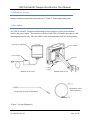
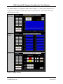
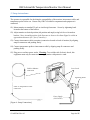
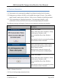
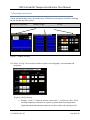
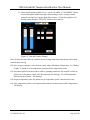
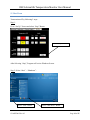
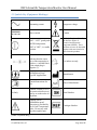
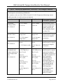
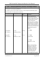
CIRCA Scientific Temperature Monitor User Manual CIRCA Scientific Temperature Monitoring System Model CS-1000 CIRCA Scientific, LLC 14 Inverness Drive East, Suite H240 Englewood, CO 80112 (303) 951-8767 CS-ART2005 Rev. 03 Page 1 of 27 CIRCA Scientific Temperature Monitor User Manual Table of contents: 1. General warnings and cautions … Page 3 2. Indications for use … Page 4 3. Description … Page 4 4. Alarm System Overview … Page 7 5. Setup instructions … Page 8 6. Check-out instructions … Page 9 7. Operating instructions … Page 10 8. Shut-Down … Page 12 9. Cleaning and Disinfection … Page 14 10. Maintenance … Page 14 11. Storage and Transportation … Page 15 12. Troubleshooting … Page 16 13. Accessories … Page 18 14. Technical Information … Page 19 15. Symbols Key … Page 21 16. Electromagnetic Compatibility … Page 22 CS-ART2005 Rev. 03 Page 2 of 27 CIRCA Scientific Temperature Monitor User Manual 1. General warnings and cautions: Rx Only: Federal (U.S.A.) law restricts this device to sale by or on the order of a physician. The monitor is designed for use with CIRCA Scientific interconnect cables and temperature probes only. Incompatible components can result in degraded performance and could lead to damage to the unit. No modification of this equipment is allowed. Never pour any liquid into an opening. This may cause fire or electrical shock. Do not cover the openings. Overheating may occur as the openings on the enclosure are for air convection. If the equipment is not in use, disconnect it from the power source to avoid damage by transient overvoltage. Do not remove cover. No user serviceable parts inside. There is a danger of shock if incorrectly serviced. There is a danger of explosion if battery is incorrectly replaced. Refer servicing to qualified personnel. To avoid the risk of electric shock, this equipment must only be connected to a supply mains with protective earth. To avoid product damage, do not repair or replace power supply and USB Cable. Refer servicing to qualified personnel. This equipment needs special precautions regarding EMC (Electromagnetic Compatibility) and needs to be put into service according to the EMC information provided in section 16 “Electromagnetic Compatibility”. Do not connect additional accessory equipment to the analog and digital interfaces for signal input or output. Personnel who connect additional equipment configure a medical system; degraded performance and damage to the unit could occur. Part of defibrillation proof protection is provided by the S-Cath temperature probe. Do not use with any other applied part. Caution is a statement that alerts the user to the possibility of a problem with the device associated with its use or misuse. Such problems include device malfunction, device failure, damage to the device or damage to other property. Warning is a statement that alerts the user to the possibility of injury, death, or other serious adverse reactions associated with the use or misuse of the device. CS-ART2005 Rev. 03 Page 3 of 27 CIRCA Scientific Temperature Monitor User Manual 2. Indications for use: Display continuous temperature measurement (C) from 12-sensor temperature probe. 3. Description: The CIRCA Scientific Temperature Monitoring System consists of a touch-screen monitor, bracket, and power supply. The monitor is to be used with CIRCA Scientific interconnect cable and temperature probe only. The interconnect cable and temperature probe are sold separately. Touch Screen Monitor Power Button Power Supply Bracket USB Cable Monitor (Front View) Temperature Probe (Sold Separately) Monitor (Back View) Interconnect Cable (Sold Separately) [Figure 1: System Equipment] CS-ART2005 Rev. 03 Page 4 of 27 CIRCA Scientific Temperature Monitor User Manual The monitor displays 12 temperature probe sensor readings (C), the maximum temperature of all sensors, and contains an alarm system with user-selected levels. The monitor features the following three screens: Maximum Temperature Channel Graphs Set Up [Figure 2: Display Screens] CS-ART2005 Rev. 03 Page 5 of 27 CIRCA Scientific Temperature Monitor User Manual Note: numbered channels 1 through 12 correspond to each sensor located within the S-Curve of the temperature probe. Channel number begins with sensor #1 located on distal end. Sensor #1 #2 #3 ….. #12 [Figure 3: Temperature Probe Sensor Location] CS-ART2005 Rev. 03 Page 6 of 27 CIRCA Scientific Temperature Monitor User Manual 4. Alarm System Overview The alarm system provides visual and audible feedback when a sensor temperature is equal to and above the user-selected value. The alarm system is intended to provide operator feedback regarding temperature compared to user-selected levels only; it does not provide physiological alarm conditions. The visual and audible signal is triggered when a sensor temperature is equal to and above the set value. Alarm levels are set by the operator (see Operating Instructions section below for setting instructions). WARNING is a lower priority than ALARM. WARNING is identified by YELLOW. ALARM is identified by RED. AUDIO OFF inactivates the audible signal, only until another event occurs. Another event includes maximum temperature increasing from warning to alarm level, or temperature drops below warning or alarm value, then increases and is equal and above set value. [Figure 4: Warning Signal] [Figure 5: Alarm Signal] CS-ART2005 Rev. 03 Page 7 of 27 CIRCA Scientific Temperature Monitor User Manual 5. Setup instructions: The operator is responsible for checking the compatibility of the monitor, interconnect cable, and temperature probe before use. Ensure only CIRCA Scientific components and equipment is connected. S1) Mount monitor to standard IV pole or similar rigid structure. Secure by tightening knob located at the bottom of the bracket. S2) Adjust monitor to desired position (tilt position and angle) using lock levers located on bracket. (Note: intended position of the Operator to observe the Alarm Signal is within an approximate distance of 4.5 feet (1.4 meters).) S3) Connect interconnect cable to monitor (connection located on back of monitor) by aligning snap-fit connectors and pushing firmly. S4) Connect temperature probe to interconnect cable by aligning snap-fit connectors and pushing firmly. S5) Plug power cord into power outlet. Warning: To avoid the risk of electric shock, this equipment must only be connected to a supply mains with protective earth. Cable to Monitor connection Lever Locks Tightening Knob Cable to Temperature Probe connection Power Supply (100-240 AC) [Figure 6: Setup Connections] CS-ART2005 Rev. 03 Page 8 of 27 CIRCA Scientific Temperature Monitor User Manual 6. Check-out Instructions C1) Turn monitor on by momentarily pushing Power Button located on back of monitor. C2) During start-up, monitor will deliver a test audible alarm signal (3 beeps). If no audible signal is heard, sound system is defective. Refer service of monitor to qualified personnel. C3) Verify temperatures are displayed on monitor. If no temperature displays, verify connections are fully seated and resolve any error messages displayed on monitor. The following messages will display if cables are not connected or unit does not initialize: Message Resolution Touch “OK” button. Ensure USB Cable (back of monitor) is firmly seated in ports. Reconnect cable. Proceed with Shut Down from Windows screen. Turn monitor back on by momentarily pushing Power Button on back of monitor. Ensure temperature probe is firmly seated to interconnect cable and interconnect cable is firmly seated to monitor. When properly connected, message will terminate and temperature readings display. Touch “OK” button. Ensure USB Cable (back of monitor) is firmly seated in ports. Reconnect cable. Proceed with Shut Down from Windows screen. Turn monitor back on by momentarily pushing Power Button on back of monitor. [Table 1: Message Overview] C4) Proceed with operating instructions below. CS-ART2005 Rev. 03 Page 9 of 27 CIRCA Scientific Temperature Monitor User Manual 7. Operating instructions Screen navigation and set-up is by touch screen. Different screens may be selected by touching the tab near the top of the screen. Maximum Temperature Channel Graphs Set Up Touch Tab to Select [Figure 7: Display Screens] O1) Select “Set Up” tab to set desired alarm system levels and graph y-axis minimum and maximum. [Figure 8: Set Up Screen] a. Settings – touch “+” button to increase value, touch “-“ to decrease value. (Note: warning temperature cannot be set equal to or greater than alarm temperature. Graph maximum and minimum cannot be set below alarm and warning levels.) CS-ART2005 Rev. 03 Page 10 of 27 CIRCA Scientific Temperature Monitor User Manual b. Alarm and Warning Audible Levels – touch “ALARM” or “WARNING” button to hear and update audible tone and volume settings. (Note: warning volume cannot be set equal to or greater than alarm volume.) Touch bar graph level to desired setting and then “UPDATE” button to save and exit. [Figure 9: Tone and Volume Setting] Note: all user selected values are retained; the last settings used before shut down will be those recalled upon start-up. O2) Once set up is complete, select desired screen, either “Maximum Temperature” or “Channel Graphs” in which to view temperatures measured by the temperature probe. O3) Disconnect probe from interconnect cable by grasping connectors. Do not pull on cable or probe wire to disconnect. (Note: after disconnecting, the message “No valid temperature data. Please check probe.” will display.) O4) Prepare temperature probe for patient use per temperature probe‟s instructions for use. O5) Once temperature probe is set in patient and connected to interconnect cable, temperatures will display. CS-ART2005 Rev. 03 Page 11 of 27 CIRCA Scientific Temperature Monitor User Manual 8. Shut-Down Turn monitor off by following 3 steps: Step 1: Go to “Set Up” Screen and select “Stop” Button: Select “Stop” Button After Selecting “Stop”, Program will exit to Windows Screen. Step 2: Select “Start” – “Shutdown”: Select “Start” Button CS-ART2005 Rev. 03 Select “Shut Down” Button Page 12 of 27 CIRCA Scientific Temperature Monitor User Manual Step 3: Select “OK” and unit will shut down: Select “OK” Button CS-ART2005 Rev. 03 Page 13 of 27 CIRCA Scientific Temperature Monitor User Manual 9. Cleaning and Disinfection Disconnect from power before cleaning. Use a damp cloth. Do not use liquid or spray detergents for cleaning. Wipe outer surfaces with damp cloth and let dry. Do not rinse, soak, wash or sterilize. If disinfection is required, apply non-abrasive/non-corrosive disinfection fluid to disposable cloth, wipe outer surfaces, and then let dry. 10. Maintenance Routine Visual Inspection Visually inspect the monitor and all accessories at least once before each use. Inspect the power cord, cables, and monitor for damage, wear, and loose components. Particular attention should be made to the power cord and interconnect cable for insulation damage such as cuts, brittleness, cracking, and bare spots. Do not use if equipment appears damaged. Annual Safety Inspection and Accuracy Test The following safety inspection and accuracy test should be performed by hospital‟s equipment service department at least every 12 months: Inspect the equipment and accessories for mechanical damage. Inspect all labels and markings for legibility. Check temperature accuracy with the following test: Equipment: 10K Resistor Test Part (available from CIRCA Scientific) 1. Connect Test Part to Interconnect Cable. 2. Turn unit on. 3. Observe temperature readings (12) displayed on the monitor. 4. Calculate the measurement error for each individual Output Temperature measurement by subtracting reading from 25.0C. 5. Ensure that the measurement error is not greater than 0.3C. Do not use equipment if the inspections or test reveal a defect. The equipment has no serviceable parts. Warning: to prevent shock, do not remove cover. Refer servicing to qualified personnel. CS-ART2005 Rev. 03 Page 14 of 27 CIRCA Scientific Temperature Monitor User Manual 11. Storage & Transport Do not leave this equipment in an environment where the storage temperature may go below -20C (-4F) or above 60C (140F). This could damage the equipment. If shipping equipment, pack in original carton and packing materials. If original packing material is not available, cover monitor, pack with foam, and ship in sturdy box to prevent damage during transport. CS-ART2005 Rev. 03 Page 15 of 27 CIRCA Scientific Temperature Monitor User Manual 12. Troubleshooting Problem Resolution Message Touch “OK” button. Ensure USB Cable (back of monitor) is firmly seated in ports. Reconnect cable. Proceed with Shut Down from Windows screen. Turn monitor back on by momentarily pushing Power Button on back of monitor. Message Ensure temperature probe is firmly seated to interconnect cable and interconnect cable is firmly seated to monitor. Replace probe and/or interconnect cable if no temperature data can be displayed after verifying connections. Message Touch “OK” button. Ensure USB Cable (back of monitor) is firmly seated in ports. Reconnect cable. Proceed with Shut Down from Windows screen. Turn monitor back on by momentarily pushing Power Button on back of monitor. Monitor does not boot up and BIOS Configuration reset to default. The computer inside the monitor is provided with a battery-powered realtime clock circuit. The battery has no power. Warning: There is a danger of explosion if battery is incorrectly replaced. Refer servicing to qualified personnel. CS-ART2005 Rev. 03 Page 16 of 27 CIRCA Scientific Temperature Monitor User Manual Problem Resolution “----“ is displayed for an individual sensor temperature reading and an individual sensor graph (under “Channel Graphs” display) is orange. No action required. Frozen Screen: Monitoring indicator does not flash. Shut down unit and re-start. The four dashes („----„) and orangecolored graph indicate an individual sensor wire has failed. [Table 2: Troubleshooting Overview] CS-ART2005 Rev. 03 Page 17 of 27 CIRCA Scientific Temperature Monitor User Manual 13. Accessories The monitor is designed for use with CIRCA Scientific interconnect cables and temperature probe only. The interconnect cables and temperature probes are sold separately. Contact CIRCA Scientific or Authorized Distributor for ordering information. The “Recorder” Port located on the back of the monitor is intended to connect with the 0 to 5V analog input of a recording device that is compliant with IEC 60601-1. Do not connect this port to any other device. Caution: Use of accessories or replacement parts not supplied by CIRCA Scientific can result in degraded performance and could lead to damage to the unit. Warning: Use of cables and accessories other than those supplied by CIRCA Scientific may result in increased emissions or decreased immunity of the equipment. Power Supply (use only Sinpro model MPU50-105 power supply) Recorder Port Monitor (Front View) Temperature Probe (Sold Separately) USB Cable Monitor (Back View) Interconnect Cable (Sold Separately) [Figure 10: Equipment Illustration] CS-ART2005 Rev. 03 Page 18 of 27 CIRCA Scientific Temperature Monitor User Manual 14. Technical Information Classification Class I Defibrillation-Proof Type BF Applied Part Continuous Operation Software Revision level 1.1 Electrical (Mains) Mains Supply Voltage: 100-240V AC Mains Supply Frequency: 47-63 Hz Mains Rated Input: 1.35A Electrical (Power Supply) Output Voltage: 12V DC Max Current: 3.75A Max Use only Sinpro model MPU50-105 power supply. Electrical (Monitor Power Input) Input Voltage: 12-19 V DC Electrical (Safety and Electromagnetic Compatibility) Meets IEC 60601-1:1988 +A1:1991 + A2:1995 User Settings Alarm and Warning Temperature Levels in 0.1C increments Current: 3.75-2.63A Meets IEC 60601-1-2:2007 Alarm and Warning Tone and Volume 1 – 10 in single digit increments Graph y-axis Minimum and Maximum in 1C increments Setting range = 0C to 90C Measurement Display Update rate = 50 milliseconds Graph time span = 60 seconds Accuracy = ± 0.3C Precision = 0.1C Alarm System Intended position of the Operator to observe the Alarm Signal is within an approximate distance of 4.5 feet (1.4 meters). Alarm Signal Sound Pressure Range = 45 to 85 dB CS-ART2005 Rev. 03 Page 19 of 27 CIRCA Scientific Temperature Monitor User Manual Physical Dimensions (monitor): 10.2” W x 7.8” H x 3.25” D 258 W x 199 H x 83 D (mm) Weight: 5.5 lbs. (2.6 kg) Disposal No special precautions are required. Dispose of equipment per hospital policy. EU Only: Products affected by the directive Waste of Electrical and Electronic Equipment (WEEE). These products are not to be discarded together with non-electrical or non-electronic products. [Table 3: Technical Information] CS-ART2005 Rev. 03 Page 20 of 27 CIRCA Scientific Temperature Monitor User Manual 15. Symbols Key (Equipment Markings) Alternating current Dangerous voltage Direct current Caution “ON” / “OFF” (push-push) NOTE Each position, "ON" or "OFF", is a stable position. EU Only: Products affected by the directive Waste of Electrical and Electronic Equipment (WEEE). These products are not to be discarded together with non-electrical or non-electronic products. Centre Positive. Indicates that the center (tip) of the output plug is Positive (+) and the barrel of the output plug is Negative (-). Rx Only For indoor use only Defibrillation-Proof Type BF Applied Part Manufacturer Consult Instructions for Use Date of Manufacture Caution: Federal (U.S.A.) law restricts this device to sale by or on the order of a physician Serial Number Caution: part of defibrillation proof protection is provided by the S-Cath temperature probe. Do not use with any other applied part. Catalogue Number [Table 4: Symbols Key] CS-ART2005 Rev. 03 Page 21 of 27 CIRCA Scientific Temperature Monitor User Manual 16. Electromagnetic Compatibility Warning: Use of cables and accessories other than those supplied and sold by CIRCA Scientific may result in increased emissions or decreased immunity of the equipment. Warning: The equipment should not be used adjacent to or stacked with other equipment. If adjacent or stacked use is necessary, the monitor should be observed to verify normal operation. Normal operation is considered as absence of unusual, erratic variations in temperature readings. The equipment may be affected by portable and mobile RF (Radio Frequency) communications equipment. Table 5 – Guidance and manufacturer’s declaration – Electromagnetic Emissions The CIRCA Scientific CS-1000 Temperature Monitoring System is intended for use in the electromagnetic environment specified below. The customer or the user of the CIRCA Scientific CS-1000 Temperature Monitoring System should assure that it is used in such an environment. Emissions test Compliance Electromagnetic environment - guidance RF emissions Group 1 The CIRCA Scientific CS-1000 Temperature Monitoring System uses RF energy only for its internal function. Therefore, its RF emissions are very low and are not likely to cause any interference in nearby electronic equipment. CISPR 11 RF emissions Class A CISPR 11 Harmonic emissions Class A IEC 61000-3-2 Voltage fluctuations/ flicker emissions Complies The CIRCA Scientific CS-1000 Temperature Monitoring System is suitable for use in all establishments other than domestic and those directly connected to the public low-voltage power supply network that supplies buildings used for domestic purposes. IEC 61000-3-3 CS-ART2005 Rev. 03 Page 22 of 27 CIRCA Scientific Temperature Monitor User Manual Table 6 – Guidance and manufacturer’s declaration – Electromagnetic Immunity The CIRCA Scientific CS-1000 Temperature Monitoring System is intended for use in the electromagnetic environment specified below. The customer or the user of the CIRCA Scientific CS-1000 Temperature Monitoring System should assure that it is used in such an environment. Immunity test IEC 60601 test level Compliance level Electromagnetic environment - guidance Electrostatic discharge (ESD) ± 6 kV contact ± 6 kV contact ± 8 kV air ± 8 kV air Electrical fast transient / burst ± 2 kV for power supply lines ± 2 kV for power supply lines IEC 61000-4-4 ± 1 kV for input / output lines ± 1 kV for input / output lines Surge ± 1 kV line(s) to line(s) ± 1 kV line(s) to line(s) ± 2 kV line(s) to earth ± 2 kV line(s) to earth <5 % UT (>95 % dip in UT) for 0,5 cycle <5 % UT (>95 % dip in UT) for 0,5 cycle 40 % UT (60 % dip in UT) for 5 cycles 40 % UT (60 % dip in UT) for 5 cycles 70 % UT (30 % dip in UT) for 25 cycles 70 % UT (30 % dip in UT) for 25 cycles <5 % UT (>95 % dip in UT) for 5 s <5 % UT (>95 % dip in UT) for 5 s IEC 61000-4-2 IEC 61000-4-5 Voltage dips, short interruptions and voltage variations on power supply input lines IEC 61000-4-11 CS-ART2005 Rev. 03 Floors should be wood, concrete or ceramic tile. If floors are covered with synthetic material, the relative humidity should be at least 30%. Mains power quality should be that of a typical commercial or hospital environment. Mains power quality should be that of a typical commercial or hospital environment. Mains power quality should be that of a typical commercial or hospital environment. If the user of the CIRCA Scientific CS1000 Temperature Monitoring System requires continued operation during power mains interruptions, it is recommended that the CIRCA Scientific CS1000 Temperature Monitoring System be powered from an uninterruptible power supply or a battery. Page 23 of 27 CIRCA Scientific Temperature Monitor User Manual Power frequency (50/60 Hz) magnetic field IEC 61000-4-8 3 A/m 3 A/m Power frequency magnetic fields should be at levels characteristic of a typical location in a typical commercial or hospital environment. Note: UT is the a.c. mains voltage prior to application of the test level. CS-ART2005 Rev. 03 Page 24 of 27 CIRCA Scientific Temperature Monitor User Manual Table 7 – Guidance and manufacturer’s declaration – Electromagnetic Immunity The CIRCA Scientific CS-1000 Temperature Monitoring System is intended for use in the electromagnetic environment specified below. The customer or the user of the CIRCA Scientific CS-1000 Temperature Monitoring System should assure that it is used in such an environment. Immunity test IEC 60601 test level Compliance Electromagnetic environment level - guidance Portable and mobile RF communications equipment should be used no closer to any part of the CIRCA Scientific CS-1000 Temperature Monitoring System, including cables, than the recommended separation distance calculated from the equation applicable to the frequency of the transmitter. Recommended separation distance: Conducted RF 3 Vrms IEC 61000-4-6 150 kHz to 80 MHz Radiated RF 3 V/m IEC 61000-4-3 80 MHz to 2,5 GHz 3 Vrms d = 1.2 √ 3 V/m d = 1.2 √ 80 to 800 MHz d = 2.3 √ 800 MHz to 2.5 GHz Where is the maximum output power rating of the transmitter in watts (W) according to the transmitter manufacturer and d is the recommended separation distance in meters (m). Field strengths from fixed RF CS-ART2005 Rev. 03 Page 25 of 27 CIRCA Scientific Temperature Monitor User Manual transmitters, as determined by an electromagnetic site (a) survey should be less than the compliance level in each (b) frequency range . Interference may occur in the vicinity of equipment that include RF transmitters or that apply RF electromagnetic energy for diagnosis, i.e. equipment marked with the following symbol: Note 1: At 80 MHz and 800 MHz, the higher frequency range applies. Note 2: These guidelines may not apply in all situations. Electromagnetic propagation is affected by absorption and reflection from structures, objects and people. (a) Field strengths from fixed transmitters, such as base stations for radio (cellular/cordless) telephones and land mobile radios, amateur radio, AM and FM radio broadcast and TV broadcast cannot be predicted theoretically with accuracy. To assess the electromagnetic environment due to fixed RF transmitters, an electromagnetic site survey should be considered. If the measured field strength in the location in which the CIRCA Scientific CS-1000 Temperature Monitoring System is used exceeds the applicable RF compliance level above, the CIRCA Scientific CS1000 Temperature Monitoring System should be observed to verify normal operation. If abnormal performance is observed, additional measures may be necessary, such as re-orienting or relocating the CIRCA Scientific CS-1000 Temperature Monitoring System. (b) Over the frequency range 150 kHz to 80 MHz, field strengths should be less than 3 V/m. Note: If high frequency surgical equipment is used at the same time and interferes with the operation of the CIRCA Scientific CS-1000 Temperature Monitoring System, additional measures may be necessary, such as re-orientation of cables, relocation, and/or connecting the hospital grade power cable into a different grounded receptacle or separate grounded power source. CS-ART2005 Rev. 03 Page 26 of 27 CIRCA Scientific Temperature Monitor User Manual Table 8 – Recommended separation distances between portable and mobile RF communications equipment and the CIRCA Scientific CS-1000 Temperature Monitoring System The CIRCA Scientific CS-1000 Temperature Monitoring System is intended for use in an electromagnetic environment in which radiated RF disturbances are controlled. The customer or the user of the CIRCA Scientific CS-1000 Temperature Monitoring System can help prevent electromagnetic interference by maintaining a minimum distance between portable and mobile RF communications equipment (transmitters) and the CIRCA Scientific CS-1000 Temperature Monitoring System as recommended below, according to the maximum output power of the communications equipment. Rated maximum output power of transmitter 150 kHz to 80 MHz 80 MHz to 800 MHz 800 MHz to 2.5 GHz W d = 1.2 √ d = 1.2 √ d = 2.3 √ 0.01 0.12 meters 0.12 meters 0.23 meters (4.7 inches) (4.7 inches) (9.1 inches) 0.38 meters 0.38 meters 0.73 meters (15.0 inches) (15.0 inches) (28.7 inches) 1.2 meters 1.2 meters 2.3 meters (3.9 feet) (3.9 feet) (7.6 feet) 3.8 meters 3.8 meters 7.3 meters (12.5 feet) (12.5 feet) (24.0 feet) 12 meters 12 meters 23 meters (39.4 feet) (39.4 feet) (75.5 feet) 0.1 1 10 100 Separation distance according to frequency of transmitter For transmitters rated at a maximum output power not listed above, the recommended separation distance d in meters (m) can be estimated using the equation applicable to the frequency of the transmitter, where P is the maximum output power rating of the transmitter in watts (W) according to the transmitter manufacturer. Note 1: At 80 MHz and 800 MHz, the separation distance for the higher frequency range applies. Note 2: These guidelines may not apply in all situations. Electromagnetic propagation is affected by absorption and reflection from structures, objects and people. CS-ART2005 Rev. 03 Page 27 of 27