1
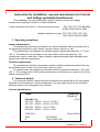
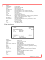
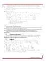
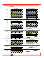
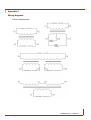
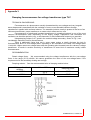
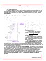
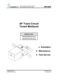
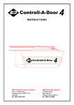
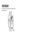
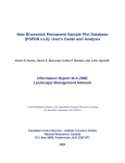
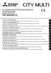
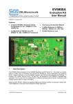
Instruction for installation, use and maintenance for
Current and Voltage (potential) transformers
1VLM000610 Rev.1, en 2008.12.3
Instruction for installation, use and maintenance for Current
and Voltage (potential) transformers
This installation, use and maintenance guide is valid for current and voltage
transformers operating in outdoor or indoor conditions.
These instructions are valid for Current transformer type:
TPU; TPO; TP; TTR; BB; BBO;
KOKS; KOFD; KOFA; IHBF
Voltage transformers types: TJC; TDC; TDO; TJO; TJP;
TDP; KGUG; KGUGI; KRED
1. Operating conditions
Indoor transformers
The transformers should be mounted in dry indoor conditions where the ambient air is
not significantly polluted by dust, smoke, corrosive cases, vapours or salt.
The transformers are designed for standard ambient temperature between –5 °C and
+40 °C. The altitude for use should be lower than 1000 m above the sea level. The
transformers may be used also in higher ambient temperatures and higher altitudes when
agreed upon with the manufacturer.
Outdoor transformers
The transformers should be mounted in outdoor conditions where the ambient air may
be polluted by dust, smoke, corrosive cases, vapours or salt.
The transformers are designed for standard ambient temperature between –40°C and
+40 °C. The average value of the ambient temperature, measured over a period of 24 hours,
should not exceed 35°C.
2. Technical details
The technical details for each individual transformer are mentioned on the rating plate
fastened on the transformer. Values mentioned on the rating plate must not be exceeded.
Markings used on the rating plate are as follows:
Current transformers
ABB
200-400/1/1 A
1S1-1S2 200/1A
1S1-1S3 400/1A
2S1-2S2 200/1A
2S1-2S3 400/1A
12/28/75 kV
2002
E
1234567890
TPU 40.13
50 Hz
5VA cl. 0.5 FS 5
10VA cl. 0.5 FS 5
5VA cl. 5P15
10VA cl. 5P15
50(1s)/125 kA
IEC 60044-1
TCM 212/95-2150
1VLM000610 Rev.1, en 2008.12.3
Where:
1234567890
TPU 40.13
50Hz
200-400/1/1 A
1S1-1S2
1S1-1S3
5VA
0.5, 5P
FS5
12/28/75 kV
serial number
transformer type code
rated frequency
rated transformer ratio
terminal marking for core number 1, first tap
terminal marking for core number 1, second tap
rated output
accuracy classes
instrument security factor
highest voltage for equipment / power-frequency withstand
voltage / rated lightning-impulse voltage
referred standard(s)
rated short time thermal current (thermal time) / rated
dynamic current
year of production
temperature class
Type approval mark
IEC 60044-1
50(1s)/125kA
2002
E
TCM ……
Voltage transformers
ABB
6600:√3/100:√3/100:3 V
a-n
30VA cl.0.5
da-dn
30VA cl.6P
7.2/20/60 kV
2002
IEC 60044-2
E
TCM 212/95-2151
Where:
1234567890
TJC 4
50Hz
6600:√3/100: √3/100:3 V
a-n
da-dn
30VA
0.5, 6P
12/28/75 kV
IEC 60044-2
2002
E
TCM……
1234567890
TJC 4
50 Hz
400 VA
serial number
Transformer type code
rated frequency
rated voltage ratio
terminal marking for first secondary winding
terminal marking for residual (open-delta) winding
rated output
accuracy classes
highest voltage for equipment / power-frequency
withstand
voltage / rated lightning-impulse voltage
referred standard
year of production
temperature class
Type approval mark
1VLM000610 Rev.1, en 2008.12.3
3. Instruction for installation
General information
Instrument transformer is an electrical equipment and the electrical installation shall be
done by skilled person only. National legislation can set down the minimum age and the
criteria for competence of skilled persons working on, with, or near an electrical installation.
Where is not the national legislation requirements for competence, the criteria shall be used
at least according to EN 50110-1.
Safety instructions
1. Always consider transformer as a part of the circuit to which it is connected, and do
not touch the leads and terminals or other parts of the transformer unless they are
known to be grounded.
2. Always ground the metallic bases of instrument transformer.
3. Always ground one secondary terminal of the transformer, except if the windings are
connected to open delta. When the secondary of transformer is interconnected, there
should be only one grounded point to prevent accidental paralleling with system
grounding wire. In case of disconnection from the ground, the grounding screw has to
be removed from the secondary terminal. Connection between secondary terminal
and base plate (ground) is shown on the picture “Crossection of single line terminal
box“
4. Always short-circuit the secondary of the current transformer, which is not currently in
use to prevent secondary voltages which may be hazardous to personnel or damaging
to the transformer’s secondary. The secondary like this must be additionally grounded.
5. Never short-circuit the secondary terminal of a voltage transformer even this is not in
use. A secondary short-circuit will cause the unit to overheat and fail in a very short
period of time.
6. Protection of single pole insulated voltage transformers against feroresonance
phenomena is stated in appendix 3. – Damping of the feroresonance in Voltage
transformers type TJC.
7. In case of the current transformer with voltage indication (coupling electrode included)
is secondary terminal box equiped with PE terminal, which is connected with earthing
screw to the base plate, which must be generally earthed.
Connection between secondary terminal and base plate is shown on the picture
“Crossection of single line terminal box“
Attention: Terminal PE must be always earthed, this is hold generally, even if the base
plate is removed. In case of disassembling the base plate, producer doesn’t
warranting the earthing.
Mounting
Following information is general and some details can differentiate according to type
and variants of transformers. It is necessary to combine it with other technical and marketing
specifications like catalogues, dimensional drawings and rating plate for specific transformer
type.
Indoor current and voltage transformers
The mounting position of the indoor transformer can be freely chosen. The transformer
is fixed using the mounting base with four screws M10 and washers. Fastening must be done
on a smooth surface.
There is a M8 screw for earthing the transformer on the base plate.
1VLM000610 Rev.1, en 2008.12.3
Outdoor current and voltage transformers
The mounting position of the outdoor transformer is only horizontal. The other position
can be agreed with the supplier. The transformer is fixed using the mounting base (VT) with
four screws M10 and washers or two U profiles (CT) with M12 screws. Fastening must be
done on a smooth surface.
There is a M12 screw for grounding of current transformer and M8 screw for grounding
of voltage transformer.
Primary connection
Primary terminals of the current transformer are made of cooper and they are silver or
tin plated. There are M12 screws used for fastening of primary conductor to the terminal. For
primary reconnectible transformers the ratio can be reconnected by changing position of the
links fixed by M8 screws without removing already fitted primary conductors.
Maximum allowed torques for screw connections of current transformers:
Screw
Max. torque [Nm]
Min. torque [Nm]
M5
3.5
2.8
M6
4
3
M8
20
16
M10
20
16
M12
70
56
Maximum allowed torque for screw connection of voltage transformer is 20 Nm.
Maximum allowed cantilever strength is: Voltage transformers 2000 N.
Current transformers 5000 N.
1VLM000610 Rev.1, en 2008.12.3
Secondary connections
The terminals, screws, nuts and washers are made of stainless steel. Secondary
grounding screws and secondary terminal fastening screws are made of nickel-plated brass.
The secondary terminal cover box for indoor use is made from the plastic and provided
with three detachable threaded inserts Pg16. The terminals are provided with M5 screws for
secondary wiring connection and with through going holes for direct earthing of the
secondary circuit by M5 screws. The terminal cover is seal able.
The secondary cover for outdoor CT is made of epoxy resin and provided with one
insert Pg21. The secondary cover for outdoor VT is made of plastic and provided with two
insert Pg21.
Degrees of IP protection
Indoor transformers: IP40, or IP30 for transformers TTR, BB, KOKS
Outdoor transformers: IP54
For terminal marking see appendix 1.
Details of current transformers casted terminal boxes
TJC,TDC
TJC7
TJC,TDC
TJP,TJC,TDC
TJO7
TJO6,TDO6
Details of voltage transformers casted terminal boxes
1VLM000610 Rev.1, en 2008.12.3
Cross section of single line secondary terminal box
Capacitive voltage indicator (divider)
The transformer can be supplied with the capacitive voltage indicator on the request.
There are two possible solutions:
a. HR – Indicator complies with the IEC 61234-5 standard for high resistive
voltage indicators
b. CE – Where the values of capacity C1 and C2 are measured. C1 is the
capacitance between primary winding and Ck terminal and C2 is the
capacitance between grounded parts and CK terminal. These values are
mentioned on the rating plate.
CE capacity according to nominal voltage
Ub (kV)
C1 (pF)
C2 (pF)
3 – 5,5
28 – 55
5,5 – 7,2
23 – 40
20 - 90
10 – 13,8
19 – 33
13,8 – 17,5
13 – 23
20 – 24
10 - 18
Fuses
The fuse can be a part of a supply of voltage transformers with fuse. We can supply
following fuses:
0.3A – 12 and 24 kV products… fuse type JT6 specially designed for voltage
transformers
0.6A – 12 kV products ……… …fuse type JT6 specially designed for voltage
transformers
2A – 6.3A all products up to 36 kV …IEC fuses manufacturer SIBA
2A
products up to 36kV …….. IEC fuses manufacturer BUSSMANN
8. Instruction for use
-
Current transformers are used:
to convert large currents in the primary circuit to an appropriate level for secondary
circuit equipment (relays and meters)
1VLM000610 Rev.1, en 2008.12.3
to insulate primary and secondary circuit from each otherto protect the secondary
equipment from the harmful effects of large current appearing during the operation
(short circuits)
The use of current transformer for other purpose then described above is forbidden in
not agreed with the producer.
-
Routine test report
Together with instrument transformer are delivered:
- routine test report
- two rating plates (one plastered on the transformer and one free)
The following information can be included on the request. These are free of charge.
- theoretical current/voltage errors and phase displacement values
- theoretical excitation curves
There are additional extra paid reports which can be supplied on request:
- accuracy test report
- magnetizing curve ( for current transformers )
- additional labels (if more then 2)
- verification tests
9. Instruction for maintenance
Excessive dust or other kind of pollution must be brushed off the transformer. Polluted
transformers can be cleaned with spirit, petrol or toluene.
Traces of arcs and minor surface damages can be easily removed with sandpaper after
which the surface is to be treated by applying a thin layer of silicone paste on it.
Instruction for repairing greater surface damages must be requested from the
manufacturer.
10.
Transport and storage
The permissible transport and storage temperature is from –40 °C to +70 °C. During
transport and storage the transformers must be protected against direct sunshine. The
transformers are delivered fastened to a transport pallet.
11.
Disposal
Materials used in instrument transformers are considered as materials without
dangerous environmental impact and materials are not toxic. Disposal of instrument
transformers is controlled by national legislation of communal waste.
12.
Normative references
IEC60044-1… Instrument transformers – Current transformers
IEC60044-2… Instrument transformers – Voltage transformers
IEC61243-5… Voltage detectors – Voltage detecting systems (VDS)
IEC60529…… Degrees of protection provided by enclosures (IP Code)
ISO12100…… Safety of machinery — Basic concepts, general principles for design
EN 50110-1 …Operation of electrical installations
1VLM000610 Rev.1, en 2008.12.3
Appendix 1. Examples of secondary terminal marking for casted terminal box for current
transformers
O n e c o re
N o ta p
1s1
1s2
1 ta p
1s1
1s2
1s3
2 ta p s
1s1
1s2
1s3
1s4
3 ta p s
1s1
1s2
1s3
1s4
4 ta p s
1s1
1s2
N o ta p
1s1
1s2
1 ta p
1s1
1s2
2 ta p s
3 ta p s
N o ta p
1 ta p
1s3
1s4
1s5
1s5
1s6
T w o c o re s
2s1 2s2
1s3
2s1
2s2
2s3
1s3
1s1
1s4
1s2
2s3
2s1
2s4
2s2
1s4
1s1
1s5
1s2
1s3
2s4
2s1
2s5
2s2
2s3
1s1
1s2
3 c o re s
2s1 2s2
3s1
3s2
1s3
1s1
1s2
2s3
2s1
2s2
3s3
3s1
3s2
2 ta p s
1s3
1s1
1s4
1s2
2s3
2s1
2s4
2s2
3s3
3s1
3s4
3s2
N o ta p
1s2
1s1
2s2
2s1
4 c o re s
3s2 4s2
3s1 4s1
1 ta p
1s2
1s1
1s3
2s1
2s3
2s2
3s2
3s1
3s3
4s1
N o ta p
1s2
1s1
2s2
2s1
5 c o re s
3s2 4s2
3s1 4s1
5s2
5s1
N o ta p
1s2
1s1
2s2
2s1
6 c o re s
3s2 4s2
3s1 4s1
5s2
5s1
2 n d lin e o f te rm in a l
1 s t lin e o f te rm in a l
1s1
O n e c o re w ith C D
1s2
Ck
PE
1s1
1s2
1s3
Ck
PE
1s1
1s2
1s3
1s4
Ck
PE
1s5
1s1
1s2
1s3
1s4
Ck
PE
1s5
1s1
1s6
1s2
1s3
1s4
Ck
PE
1s1
T w o c o re s w ith C D
1s2 2s1 2s2
Ck
PE
1s3
1s1
1s2
2s3
2s1
2s2
Ck
PE
1s3
1s1
1s4
1s2
2s3
2s1
2s4
2s2
Ck
PE
1s2
1s1
3 c o re s w ith C D
2s2 3s2
2s1 3s1
Ck
PE
1s2
1s1
1s3
2s1
3s3
Ck
PE
1s2
1s1
4 c o re s w ith C D
2s2 3s2 4s2
2s1 3s1 4s1
Ck
PE
2s3
2s2
3s2
3s1
4s3
4s2
5 c o re s w ith C D
6 c o re s w ith C D
6s2
6s1
-te rm in a l n o t e a rth e d
1VLM000610 Rev.1, en 2008.12.3
-te rm in a l e a rth e d
Examples of secondary terminal marking for casted and assembled (phoenix)
terminal box for Voltage transformers
One pole insulated voltage transformer
2 measuring windings
1a
1n
2a
2n
N
PE
Measuring and residual
winding
a
n
da
dn
N
PE
2 ratios measuring winding
a1
a2
n
N
PE
a
n
N
PE
One measuring winding
Assembled secondary terminal (Phoenix)
2 measuring and residual
winding
1a
2 measuring double rations
winding
1a1
1a2
1n
2a1
2a2
2n
N
PE
a1
a2
n
da1
da2
dn
N
PE
2 ratios measuring and
residual winding
1n
2a
2n
da
dn
N
PE
Double pole insulated transformer
2 measuring windings
2 ratios measuring winding
One measuring winding
1a
1b
2a
a1
a2
b
a
b
2b
PE
PE
PE
1VLM000610 Rev.1, en 2008.12.3
Appendix 2.
Wiring diagrams
Current transformers:
1VLM000610 Rev.1, en 2008.12.3
Wiring diagrams
Voltage transformers:
1VLM000610 Rev.1, en 2008.12.3
Appendix 3.
Damping ferroresonance for voltage transformer type TJC
TECHNICAL BACKGROUND
Ferroresonance is a phenomenon usually characterized by over-voltages and very irregular
wave shapes and is associated with the excitation of one or more saturable inductors through
capacitance in parallel with nonlinear inductor. The saturable inductor usually is present in the form of an
instrument transformer, power transformer or reactor witch utilizes an iron core.
Ferroresonance of single-pole insulated transformers in unearthed network is one of the most
common ferroresonance case. Depending on the supply voltage, capacitance and inductance the
oscillation can be either periodic (over- or sub-harmonic or with fundamental frequency) or aperiodic.
Using damping resistor or VT guard in the residual voltage secondary, shown in Fig.1, can
considerably reduce the risk for ferroresonance.
There is additionally factor that can in some cases reduce or totally eliminate the risk for
ferroresonance and it is over-voltage factor. According to IEC standard is the rated over-voltage factor
1.9xUn/ 8h. Higher rated over-voltage factor shift the operating point towards lower flux values of voltage
transformer. It results in smaller sensitivity of transformer to some kind of transients usually initiate
ferroresonance.
RECOMMENDATION
Rated voltage factor: We recommended using the voltage transformers with the over-voltage
factor in the range (2.5-3) xUn/8h. We cannot guarantee the value of the over-voltage factor if the
requirements for the secondary winding are too high.
Damping resistor:
See the recommended value of damping resistor below:
Voltage of residual
winding
100:3 V
110:3 V
Value of Rdamp
22 Ω
27 Ω
Damping power
450 W
450 W
Fig.1.
1VLM000610 Rev.1, en 2008.12.3
VT Guard – function
1. VT-Guard description:
VT Guard is a preventive device against the ferroresonance phenomenon which may be
triggered in power networks with ungrounded or not directly grounded neutral point. VT Guard
should be used in cooperation with voltage transformers connected in open delta – more in
User’s manual.
Important: Read the User’s manual before use.
2. Basic operating states:
Simpl diagram
a) In case of full balance in a threephase network, there is zero voltage on an
open delta winding (VT Guard terminals)
REFI
Uo=0. No current flows through VT Guard.
The device isn’t active.
b) In case of unbalance in a threephase network, there is voltage on VT
Guard terminals Uo>0.
If the Uo is lower than threshold
voltage Ut (Ut =20-24V), then current
Uo
I=
flows
( RPTC // REFI ) + R1 + R 2
through the device.
Total resistance value is higher then
100ohm and voltage Uo is max 24V in this
case. Current flowing thorough the device
has very low value.
c) In case Uo is higher then treshold
voltage (ferroresonance), the „switching
circuit“ is switched on and current flows
trough RPTC//REFI and R1. Because of low values of these resistors there is steep increase of
current and fast ferroresonance dumping. High current flows trough the device for short time, the
PTC resistors arn’t warm up significantly.
d) In case Uo is higher then treshold voltage(earth fault), the „switching circuit“ is switched
on and current flows trough RPTC//REFI and R1. Because of low values of these resistors there is
steep increase of current. High current flows trough the device and cause to warm up PTC
resistors. PTC resistor increase their resistance (The resistance is proportional to flowing
current). Current is limited. Time needed for worming up PTC resistors for Uo = 100V is
approximately 1.4s. After earth-fault is removed, the PTC resistors cool-down (approximately 3
min). It is necessary to mount VT Guard in vertical position far from other thermal
sources.
1VLM000610 Rev.1, en 2008.12.3
1VLM000610 Rev.1, en 2008.12.3
The data and ilustrations in this catalogue are not binding.
We reserve the right to make changes of the content,
in the course of technical development of the product.
1VLM000610 Rev.1, en 2008.12.3