1
VT Guard – function
1. VT-Guard description:
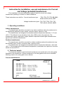
VT Guard is a preventive device against the ferroresonance phenomenon which may be
triggered in power networks with ungrounded or not directly grounded neutral point. VT Guard
should be used in cooperation with voltage transformers connected in open delta – more in
User’s manual.
Important: Read the User’s manual before use.
2. Basic operating states:
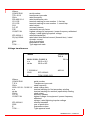
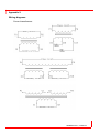
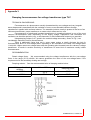
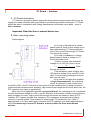
Simpl diagram
a) In case of full balance in a threephase network, there is zero voltage on an
open delta winding (VT Guard terminals)
REFI
Uo=0. No current flows through VT Guard.
The device isn’t active.
b) In case of unbalance in a threephase network, there is voltage on VT
Guard terminals Uo>0.
If the Uo is lower than threshold
voltage Ut (Ut =20-24V), then current
Uo
I=
flows
( RPTC // REFI ) + R1 + R 2
through the device.
Total resistance value is higher then
100ohm and voltage Uo is max 24V in this
case. Current flowing thorough the device
has very low value.
c) In case Uo is higher then treshold
voltage (ferroresonance), the „switching
circuit“ is switched on and current flows
trough RPTC//REFI and R1. Because of low values of these resistors there is steep increase of
current and fast ferroresonance dumping. High current flows trough the device for short time, the
PTC resistors arn’t warm up significantly.
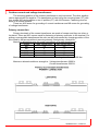
d) In case Uo is higher then treshold voltage(earth fault), the „switching circuit“ is switched
on and current flows trough RPTC//REFI and R1. Because of low values of these resistors there is
steep increase of current. High current flows trough the device and cause to warm up PTC
resistors. PTC resistor increase their resistance (The resistance is proportional to flowing
current). Current is limited. Time needed for worming up PTC resistors for Uo = 100V is
approximately 1.4s. After earth-fault is removed, the PTC resistors cool-down (approximately 3
min). It is necessary to mount VT Guard in vertical position far from other thermal
sources.
1VLM000610 Rev.1, en 2008.12.3