1
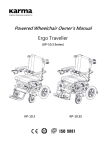
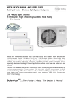
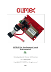
GSM/GPRS Trainer
board
User Manual
V1.11
August, 2014
2
Document Title
GSM/GPRS Trainer Kit
Version
1.1
Date
2014-08-07
Status
Released
Document Control ID
GSM/GPRS Trainer Kit V1.1
General Notes
TechShop offers this information as a service to its customers, to support application and
engineering efforts that use the products designed by TechShop. The information provided is
based upon requirements specifically provided to TechShop by the customers. TechShop has not
undertaken any independent search for additional relevant information, including anyinformation
that may be in the customer’s possession. Furthermore, system validation of this product
designed by TechShop within a larger electronic system remains the responsibility of the
customer or the customer’s system integrator. All specifications supplied herein are subject to
change.
Copyright
This document contains proprietary technical information which is the property of TechShop
Bangladesh Limited, copying of this document and giving it to others and the using or
communication of the contents thereof, are forbidden without express authority. Offenders are
liable to the payment of damages. All rights reserved in the event of grant of a patent or the
registration of a utility model or design. All specification supplied herein are subject to change
without notice at any time.
TechShop, 39, ARA Bhaban, KaziNazrul Islam Avenue, Karwan Bazar, Dhaka-1215, Bangladesh
3
Copyright © TechShop Bangladesh Ltd., Dhaka, Bangladesh, 2013
Version History
Date
2014-08-06
Version
1.0
Description
First Released
TechShop, 39, ARA Bhaban, KaziNazrul Islam Avenue, Karwan Bazar, Dhaka-1215, Bangladesh
4
Contents
Contents................ …………………………………………………………....
Version History
7
1. Introduction……………………………………………………………….. 5
2. Powering up the board
5
3. What’s on board?
6
1.SIM900 Module
7
2.Sim Connector
14
3.Audio Jack
15
4.Green Connector
15
5.Power Button
15
6.M-Reset Button
16
7.Serial Communication Pinout
16
8.Embedded Antenna
16
9.Power Indicator LED
16
10.Network Indicator LED
16
11.Power Jumper
16
12.Zif Socket
17
13.I/O Pinout
17
14.Reset Button
17
15.Status Pinout
18
16.VCC-GND Pins
18
4. Connecting SIM900 evaluation board to your PC
TechShop, 39, ARA Bhaban, KaziNazrul Islam Avenue, Karwan Bazar, Dhaka-1215, Bangladesh
18
5
Introduction:
TechshopBD’s GSM/GPRS trainer board is based on SIMCOM’s SIM900 Quad-Band
GSM/GPRS module. This trainer board provides all facilities needed to interface the
GSM/GPRS module with the serial port of any device like microcontroller or computer via
serial port. By using this boardy
boardyou can perform sms, call and internet based communication
with
ith the help of AT commands for SIM900.
Powering up the board:
Green Connector: The 2-pin
pin Green connector is for power supply. Connect the two terminals
of the power supply to the green connector and place the power jumper. Then Hit the Power
button.
As soon as you power up the board, the Green LED will start glowing and The Red one will
start blinking fast.
Fig: Green Connector and Power LED and Netlight LED
Fig: Power Button
Power
Jumper
Fig:Power LED glowing and Netlight LED Blinking
TechShop, 39, ARA Bhaban, KaziNazrul Islam Avenue, Karwan Bazar, Dhaka-1215, Bangladesh
6
What’s on Board?
1)SIM900 Module
2)SIM Socket
3)Audio Jack
4)Green Connector
5)Power button
6)Reset Button for SIM900 Module
7)Serial
Serial communication pins
8)Embedded Antenna
9)Power indicator LED
10)Network Indicator LED
11)Power Jumper
12)ZIF Socket
13)I/O Pins
14)Reset Button for Microcontroller
controller
15)Status Out Pin
16)VCC and GND Pin
TechShop, 39, ARA Bhaban, KaziNazrul Islam Avenue, Karwan Bazar, Dhaka-1215, Bangladesh
7
1) SIM900 Module:SIM900
SIM900 is a quad
quad- band GSM/GPRS module that works on frequencies
GSM 850MHz, EGSM 900MHz, DCS 1800MHz and PCS 1900 MHz. SIM900 features
GPRS multi-slot
slot class 10/ class 8(optional) and supports the GPRS coding schemes
scheme CS-1,
CS-2, CS-3, CS-4.
Fig: SIM900 Module
SIM900 has 68 STM pads and provides all hardware interfaces between the module and
customers’ boards.
•
•
•
•
Serial PORT and debug POR
PORT
T can help user easily develop user’s application.
Audio channel which includes a microphone input and a receiver input.
Programmable general purpose input and output.
The keypad and SPI display interfaces will give users the flexibility to develop
customized applications.
SIM900 is designed with power saving technique so that the current consumption is as low as
1mA in sleep mode.
SIM900 integrates TCP/IP protocol and extended TCP/IP AT commands which are very
useful for data transfer applications.
Table 1: SIM900 Key Features.
TechShop, 39, ARA Bhaban, KaziNazrul Islam Avenue, Karwan Bazar, Dhaka-1215, Bangladesh
8
TechShop, 39, ARA Bhaban, KaziNazrul Islam Avenue, Karwan Bazar, Dhaka-1215, Bangladesh
9
SIM900 works at this temperature, but some radio frequency characteristics may deviate
from GSM specification.
Table 2: Coding schemes and maximum net data rates over air interface.
Operating modes:
The table below summarizes the various operating modes of SIM900.
Table 3: Overview of operating mode.
TechShop, 39, ARA Bhaban, KaziNazrul Islam Avenue, Karwan Bazar, Dhaka-1215, Bangladesh
10
TechShop, 39, ARA Bhaban, KaziNazrul Islam Avenue, Karwan Bazar, Dhaka-1215, Bangladesh
11
SIM 900 Pin Diagram:
Table 4: Pin Description.
TechShop, 39, ARA Bhaban, KaziNazrul Islam Avenue, Karwan Bazar, Dhaka-1215, Bangladesh
12
TechShop, 39, ARA Bhaban, KaziNazrul Islam Avenue, Karwan Bazar, Dhaka-1215, Bangladesh
13
TechShop, 39, ARA Bhaban, KaziNazrul Islam Avenue, Karwan Bazar, Dhaka-1215, Bangladesh
14
To know more about this module please check this datasheet and see this AT command list
for AT command set.
2) SIM Connector:: A SIM connector is provided on Top of the board. Place your mobile
SIM here and SIM900 will be registered to the network.
Note:As
As soon as it happens, the Red LED starts blinking slowly.
Fig:SIM card Holder
TechShop, 39, ARA Bhaban, KaziNazrul Islam Avenue, Karwan Bazar, Dhaka-1215, Bangladesh
15
Fig: SIM Card Placement
3) Audio Jack:: With the audio jack you can attach headphone and make talk while sending
or receiving voice calls.
Fig: Audio Jack
Note: You have to use the headphones for mobile phone to use with this board.
Computer compatible headphones will not work.
4)
Green-Connector: The 22-pin
pin Green connector is for power supply. Connect the two
terminals of the power supply to the green connector.
Fig: Green Connector
5) Power Button: If power button is pressed then the module is on. From microcontroller
mi
we can also power the module using PC0 (pin-22).
22). If we send 1s pulse on PC0 pin then
the module will also on. When it is on if we send 1s pulse again to PC0 the module will
be turned off.
TechShop, 39, ARA Bhaban, KaziNazrul Islam Avenue, Karwan Bazar, Dhaka-1215, Bangladesh
16
Fig: Power Button
6) M_Reset Button: When we press the button the module will be reset. We can also do
this operation from microcontroller using PC1 (pin-23).
23). If we send 1s pulse on PC1 pin
then the module will reset
reset.
Fig: M-RST Button
7)
Serial communication Pin
Pin-out: Serial communication pins lets the devices to be
connected to Computers and microcontrollers via serial port. Serial port pins are also
routed to Zif socket Compatible with ATmega16 or ATmega32.
Serial Pins
Fig:Serial Communication Pins
8) Embedded Antenna: No external antenna is needed.
Fig: Embedded Antenna
9) Power Indicator LED: When is board is powered, a green led will be on.
10) Network Indicator LED
LED: A red led blinks indicating module network.
11) Power Jumper: Manually to start the module regulator we can use jumper wire.
Otherwise from microcontroller if we set the PD7(pin
PD7(pin-21)
21) high then the module regulator
will also be on. So to turn on the module we must use jumper or set PD7 pin high.
TechShop, 39, ARA Bhaban, KaziNazrul Islam Avenue, Karwan Bazar, Dhaka-1215, Bangladesh
17
Fig: Power jumper, Power & Network indicator LEDs
12) ZIF Socket: SIM900 evaluation boa
board
rd features a ZIF socket which is compatible with
ATmega16 and ATmega32. Once you place any Microcontroller of these two series that
will be interfaced with the SIM900 Module.
Fig:Zif Socket & I/O Pins & Reset Button
13) I/O Pin-out: I/O Pins are provided in both sides of the ZIF socket. With the help of these
Pin-outs,
outs, you can access all the pins of the AVR microcontroller placed on the ZIF
socket.
14) Reset Button: The Reset Button at the left corner of the board resets the microcontroller
placed on the ZIF Socket.
ket.
Fig:Reset Button
TechShop, 39, ARA Bhaban, KaziNazrul Islam Avenue, Karwan Bazar, Dhaka-1215, Bangladesh
18
15) Status Out Pin: We can figure out the module status reading this pin. Moreover from
microcontroller PC2(pin--24)
24) indicates the status of the module. If the module’s
module status is
on then this pin becomes high and vice
vice-versa.
Fig:Status Out Pin
16) VCC and GND Pins: VCC and GND pins are provided in the board so that you can
connect the board to any other external board or module.
Fig:VCC & GND Pins
4)Connecting
Connecting SIM900 evaluation board to your PC:
To interface SIM900 with your PC or laptop
laptop, you need an USB
B to serial converter.
(FT232RL).
Here we have used our USB to Serial Converter (FT232RL)
Step 1: Power up the evaluation board as me
mentioned above and Connect
ect the following pins of
the evaluation board and USB to serial converter together:
SIM900 Evaluation Board
TX
RX
GND
USB to Serial Converter(FT323RL)
RX
TX
GND
Step 2:: Then connect the USB to Serial converter to your computer through an USB A to
Mini B Cable.
TechShop, 39, ARA Bhaban, KaziNazrul Islam Avenue, Karwan Bazar, Dhaka-1215, Bangladesh
19
Step 3: Open the Serial monitor. Here we have shown the serial monitor of microC for AVR. By
clicking on MicroC for AVR>Tools>USART Terminal. The following window will appear in
that case.
Please check the AT command set of SIM900 modem.
TechShop, 39, ARA Bhaban, KaziNazrul Islam Avenue, Karwan Bazar, Dhaka-1215, Bangladesh