1
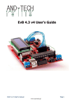
EvB 5.1 v5 User’s Guide
EvB 5.1 v5 User's manual
Page 1
www.and-tech.pl
Contents
Introduction.............................................................................................. 4
The EvB 5.1 v5 kit.................................................................................... 5
Power supply............................................................................................6
Programmer’s connector..........................................................................7
USB Port.................................................................................................. 8
RS485 Port...............................................................................................9
LED's......................................................................................................10
Pushbuttons........................................................................................... 11
Potentiometers and Buzzer....................................................................12
Power outputs ....................................................................................... 13
RTC clock and EEPROM memory.........................................................14
MMC/SD card.........................................................................................15
LED display............................................................................................ 16
LCD display............................................................................................17
IR receiver, temperature detector .........................................................18
uC pins................................................................................................... 19
Programming via USB...........................................................................21
Programming the AVR microprocessor..................................................24
with the EVB kit 4.3................................................................................24
Combining sets of EvB 5.1 BASCOM Environment..............................27
Combining sets of EvB 5.1 WinAVR Environment ................................28
Environmental Protection
............................................................................................................... 30
EvB 5.1 v5 User's manual
Page 2
www.and-tech.pl
Introduction
The EvB 5.1 is a launching set is based on two types of popular Atmel’s
microprocessors ATMega16 and ATMega32.
The board is equipped with a number of peripheral elements which endings
are connected to the pin header that enables user to quick implementation of any
project without a need to perform a dedicated board. All headers are labelled,
situated near and connected close to peripherals. It enables to intuitive
connection elements without a need to read the documentation.
The EvB 5.1 set has been designed both for non-experienced users who
make their first steps in the world of microprocessors and for those professional
programmers who search a universal platform for their projects.
Earlier versions of the EvB4.3 board were successfully applied for a number
of major projects at Polish universities and during the diploma scientific
researches. Nowadays our boards are in use at the universities of Silesia region.
EvB 5.1 v5 User's manual
Page 3
www.and-tech.pl
The EvB 5.1 v5 kit
The EvB 5.1 v5 kit includes:
• Board equipped with the following units:
AVR ATMega32 or ATMega644p Processor with DIP40 body
Real time clock PCF8563
EEPROM AT24C02 memory
TSOP4836 infra-red receiver
Infra-red transmiter
DS18B20 temperature detector
RS485 converter
micro SD card socket
8 push buttons
8 LEDs
RGB led
8 transistor outputs of 500mA each
2 analogue potentiometers
4x7 segment display
USB port
ISP port
5 pins of voltage +5V
5 pins of voltage +3.3V
5 pins of mass
• LCD of 2x16 characters
• A set of connection tools (4 single cables - 10cm, one 8-line cable of
10cm
EvB 5.1 v5 User's manual
Page 4
www.and-tech.pl
Power supply
The EvB 5.1 board may be powered by:
• USB port, set the power switch to position USB,
• External AC adapter of 9V minimal and maximum 24V voltage, to be
connected with the JACK connector (center pin is positive voltage), set the power
switch to position JACK.
The correct connection of the power source is signalized by a green LED situated
on the GND and +5V connectors.
GND and +5V connectors are situated on the board and connected to the
mass and the voltage: +5V.
EvB 5.1 v5 User's manual
Page 5
www.and-tech.pl
Programmer’s connector
At the EvB 5.1 board a 10-pin programmer’s connector is set in the ISP
KANDA standard. The connector is compatible with the most of programmers
available at the market, including the STK200 and AVRProg.
MOSI, MISO, ISP data way signals
SCK
RST Destination system reset
NC Not connected
VCC Destination system
voltage
EvB 5.1 v5 User's manual
Page 6
www.and-tech.pl
USB Port
Communication of the EvB 5.1 set with a PC has been designed to use a
USB-UART FT232RL converter (a virtual COM port). The system FT232RL is
connected to to TXD and RXD lines of the processor that leave no need for its
connecting.
A virtual COM port drivers are available at:
http://www.ftdichip.com/Drivers/VCP.htm
In addition, the system FT232RL lines were derivedXD, TXD, C3, C4, CTS,
DSR, RTS, DCD, RI, DTR to the gold pins. These lines are used for emergency
programming microprocessor but can also be used for any purpose.
EvB 5.1 v5 User's manual
Page 7
www.and-tech.pl
RS485 Port
The EvB 5.1 board is equipped with a RS485 industrial data way enabling
the board to be used in various industrial applications. Data lines (A and B) has
been directed onto a terminal block situated in the left-bottom corner of the
board. The 120R jumper is responsible for a connection of line terminator.
Pins RO, DI and the combined RE and DE were derived on a gold pin.
EvB 5.1 v5 User's manual
Page 8
www.and-tech.pl
LED's
To lit a LED situated on the board you will need to connect the mass (logic
zero) to its pin.
EvB 5.1 v5 User's manual
Page 9
www.and-tech.pl
Pushbuttons
The pushbuttons situated at the board, when pressed connect their pins
with the mass. To make the processor detect a pushbutton being pressed, apply a
connecting pull-up resistor.
EvB 5.1 v5 User's manual
Page 10
www.and-tech.pl
Potentiometers and Buzzer
Potentiometers situated on the board enable to generate any chosen
voltage between 0 and 5V.
Buzzer will put next to the potentiometers to generate sound signals, is
released after giving +5 V ba BUZ pin.
To increase the volume of the buzzer to be peeled off the white sticker
placed on it.
EvB 5.1 v5 User's manual
Page 11
www.and-tech.pl
Power outputs
The board is equipped with two outputs of 1A each (green one) and three
outputs of 500mA each. The upper output marked with + is the voltage from the
external power pack (if connected). Other slots of the connector are connected to
the mass after 5V (logic 1) being connected with reffering outputs.
EvB 5.1 v5 User's manual
Page 12
www.and-tech.pl
RTC clock and EEPROM memory
The board is equipped with two circuits using single data way 12C. The 2
kBits EEPROM memory (of the address 172 (0xAD) for reading and 173 (0xAC) for
recording) and real time clock PCF8563 (of the address 162 (0xA2) for reading
and 163 (0xA3) for recording. The PCF8563 circuit is connected with the INT pin
responsible for breaks caused by alarm and a connector for battery power source
for the clock. Battery can by also insert in socket on the bottom of boards.
EvB 5.1 v5 User's manual
Page 13
www.and-tech.pl
MMC/SD card
The board is equipped with a socket for external micro SD cards. The power
source for these cards is a 3,3V external stabilizer. The signals are adjusted to the
5V voltage by the buffer and connected to uC SPI (expect CS).
EvB 5.1 v5 User's manual
Page 14
www.and-tech.pl
LED display
In order to lit a display segment, forward a logic zero to the transistor’s base
(DIGI pins) and to the Pin responsible for the exact display’s (SEGMENT pins).
EvB 5.1 v5 User's manual
Page 15
www.and-tech.pl
LCD display
A 16-pin connector for the LCD connection based on the HD44780 controller.
Because of the electric connection, the display is being controlled using 4 or 8bit
words. The display signals are connected with the HD44780 connector labelled
underneath. The display’s contrast may be adjusted by the potentiometer (marked
at the drawing below).
Jumper mark as BL enable LCD BackLight (enable by +5V).
EvB 5.1 v5 User's manual
Page 16
www.and-tech.pl
IR receiver, temperature detector
The TSOP4836 infra-red detector’s signal and the signal of the temperature
detector DS18B20, are available at the connector placed above the mentioned
devices. The left pin is connected with the temperature detector and the right pin
is connected with the receiver.
Additional temperature detectors may also be included and connected with
the connector at the top of the detector. (star mark is the mass).
EvB 5.1 v5 User's manual
Page 17
www.and-tech.pl
uC pins
All ports and the AREF pin (AC transducer’s referential voltage) are
connected to the processor’s pins. All connections descriptions are available at the
scheme below The RESET button placed next to the USB port is designed for a
hard reset of the circuit.
EvB 5.1 v5 User's manual
Page 18
www.and-tech.pl
EvB 5.1 v5 User's manual
Page 19
www.and-tech.pl
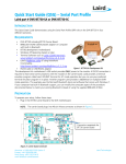
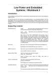
Programming via USB.
1. First, grab a program AND-Load from the website:
www.and-tech.pl in Download section
2. Extract and run the program.
Select the hex file that you wish to program the processor.
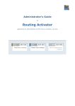
3. Select the COM port on which we have installed a set.
EvB 5.1 v5 User's manual
Page 20
www.and-tech.pl
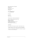
This information can be found on the COM port in the Device Manager.
EvB 5.1 v5 User's manual
Page 21
www.and-tech.pl
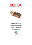
4. Then press the button, and click Open Port Program (version v3 and
earlier press the RESET button on the EvB 5.1)
5. After pressing the button will program the processor to program the
Flash memory.
When properly performed surgery will receive the message "Flash Prog
Done!"
Before disconnecting the EVB board quit AND-Load.
EvB 5.1 v5 User's manual
Page 22
www.and-tech.pl
Programming the AVR microprocessor
with the EVB kit 4.3.
1. Connection of the microprocessor into the connector programmer.
The first step is to combine the
microprocessor output with timer,
as described below.
EvB
Microprocesor port
ISP
TS
MISO
SR
SCK
CD
MOSI
RI
RESET
2. Connect the EvB 5.1 board to the computer (if the first connection of the
system will ask for drivers.
3. Download the software from a specially prepared AVRDUDE files from the
website: www.and-tech.pl/files/EvB-ISP.zip
4. Unpack the file and run the program avrdude-GUI.exe (requires. NET is at
least version 2.0).
5. As a programmer choose FT232R Synchronous BitBang (EVB)
6. Select a processor that you want to set, in our case it is ATMega16
EvB 5.1 v5 User's manual
Page 23
www.and-tech.pl
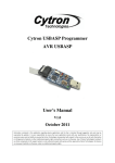
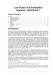
7. In the "Command line Option" type-P 19200-B ft0
Test your network connection through the Read button in the section Fuse
If the windows hFuse, lFuse numbers appear it means that the programmer
is working properly and we can program the processor in our file, if the
screen appears as shown below, this means that the board is not properly
installed on the system or poorly chosen settings.
EvB 5.1 v5 User's manual
Page 24
www.and-tech.pl
8. Select the file you want to upload to the processor and hit the button EraseWrite-Verify. After a few seconds, we should have a programmed
microprocessor.
The above description of the microprocessor programming can also be used
for the processor is not planted in the base set of EVB, but it is in this case,
remember to connect the additional power and weight to a programmable
processor (the best use of pin +5 V and GND from the board EVB).
EvB 5.1 v5 User's manual
Page 25
www.and-tech.pl
Combining sets of EvB 5.1 BASCOM
Environment
Download the latest version of AND-Load v3.2 with CL from
http://and-tech.pl/EvB4.3/AND-Load.zip
In the package, open the tab BASCOM Options → Programmer, select External
programmer
Then select the line The path to the AND-Load
In the Parameter type:
-c COMXX -h {File}
where COMXX is the COM port number on which the plate is installed
Be sure to check Use HEX file
EvB 5.1 v5 User's manual
Page 26
www.and-tech.pl
Combining sets of EvB 5.1 WinAVR Environment
Download the latest version of AND-Load v3.2 with CL from
http://and-tech.pl/EvB4.3/AND-Load.zip
Run WinAVR
In meny Tools → Options → zakładka Tools select Scheme (None – Global Tools)
EvB 5.1 v5 User's manual
Page 27
www.and-tech.pl
Modifying entry [WinAVR] Program as follows
Then in the Command line, select the path to the AND-Load
In the Parameters COM43 is the COM port number on which the plate is installed
On the Console I / O uncheck „Capture output?”
Then, after compiling the program to upload the program simply select the command:
Tools → [WinAVR] Program
EvB 5.1 v5 User's manual
Page 28
www.and-tech.pl
Environmental Protection
Marking by the symbol "crossed-out wheeled waste"tells about the ban on placing
waste electrical and electronic equipment together with other wastes, used equipment
should be collected separately. You must give used equipment to the point of collection to
ensure its recycling and recovery, as the uncontrolled release into the environment of
hazardous components in electrical and electronic equipment can become a source of
danger to the health of humans and animals and can cause long-term adverse changes in
the environment natural.
EvB 5.1 v5 User's manual
Page 29
www.and-tech.pl