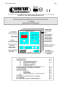
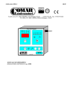
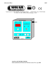
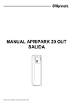
1
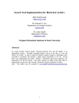
Dossena & C. S.n.c.
Dossena & C. di Barbati Agostino & C.- 26824 Cavenago D’Adda (LO) Via F.Barbarossa - Italy
Tel: +39.371.44971 - Fax: +39.371.70202 - Email: [email protected] - www.dossena.it
User’s manual
Threephase electrical multimeter Type Multiver 3DM / 3QM
18 19 20 21 22 23 24 25 26 27 28 29 30 31 32 33 34 35
MV3DM / MV3QM
1- Key to enter in configuration menu
2- Multifunction key: confirmation and save
configuration data, select autoscroll pages
3- Scroll key pages and planning default
parameter
4- Admittance cap for update
Digital 3-Phase Multimeter
Digital 3-Phase Multimeter
MV3QM
MV3DM
SETUP
AUTO
SCROLL
ENTER
SETUP
dossena & c. (Italy)
AUTO
SCROLL
ENTER
Value
measured
1
Identification
measurement
and measure unit
Multiplying
measure unit
k V
k V
1
9 9
2
3
4
5
6
dossena & c. (Italy)
11 12 13 14 15 16 17
Phase number
k V
2
9 9 9
1
3
9 9 9 9
Identification
page : 1, 2, ..
TECHNICAL CHARACTERISTICS
Supply voltage
Absorption
Input Voltage
115/230V (+15 -20)% 50/60 Hz
max 5 VA
Nominal 440Vac Max 600 Vrms phase phase
750 Vrms for 60sec./ 900Vrms for 1 sec.
In = 5A from CT
1.2 In permanent
10 In for 60 sec.
50 In for 1 sec.
3.3 kV 50 Hz for 60 sec. 4kV 1.2 / 50 µs
0 ÷ 50 °C
-20 ÷ +70 °C
Display LCD 2x16 with backlight
Frontal IP52 Case IP20
Max section of the conductor 2,5 mmq.
Max section of the conductor 4 mmq.
450 g.
Input Current
Overload
Insulation
Work ing temperature
Storage temperature
Display
Protection degree
Terminals
Terminals input current
Weight
OVERALL DIMENSIONS
53,5 mm
70,2 mm
40,8 mm
31,7 mm
104,6 mm
93,3 mm
Digital 3-Phase Multimeter
MV3QM
18 19 20 21 22 23 24 25 26 27 28 29 30 31 32 33 34 35
dossena & c. (Italy)
93,3 mm
AUTO
SCROLL
ENTER
45 mm
MV3DM
SETUP
62,3 mm
90,2 mm
Digital 3-Phase Multimeter
SETUP
AUTO
SCROLL
ENTER
1
2
3
4
5
6
11 12 13 14 15 16 17
dossena & c. (Italy)
Pag. 1
GENERAL DESCRIPTION
Three-phase multimeter , type MV3DM ( DIN rail execution ) and/or MV3QM ( panel mounting execution 96 x 96 mm. ) are measurement
electrical instruments, able to measure and visualize the main electrical parameters of each phase as well as of the full 3-phase system ( with
or without neutral wire).
SAFETY CAUTIONS
Carefully follow the installation instructions ( see next points)
Pay attention to connect the instrument without power.
Connection and installation operations must be in conformity with normal security procedures.
AUXILIARY SUPPLY
Before connecting the instrument to the aux. supply , check that the available aux. voltage is incuded in the range of acceptable voltage
values, in the manual described.
Protect the instrument with a fuse of 0.1 A.
VOLTAGE INPUTS
The instrument can work up to a maximum voltage of 600V ( phase to phase ) ; over 440V , use Voltage Transformers ( VT' s ) .
For the connections , follow the diagrams shown in the manual respecting the phase sequences.
Using Voltage Trasformer respect their input/ouput polarity.
CURRENT INPUTS
The instrument can accept input current values till 5A from Current Transformers ( CT's). The connections must be in conformity with
insertion diagrams, respecting the phases sequences, and the input/output polarity of the current transformers. It's possible to connect
directly the instrument without CT 's ; these inputs are insulated from the circuit.
Pay attention that the current value doesn’t exceed the declared value.
ATTENTION : short-circuit the secondary winding of the CT's , before disconnecting the current inputs of the instrument.
PAGES VISUALIZATION
The instrument visualizes the following measures , devided in 13 pages:
(1)
(2)
(3)
(4)
(5)
(6)
(7)
(8)
(9)
(10)
(11)
(12)
(13)
V1 / V 2 / V 3
V1-2 / V2-3 / V1-3
I1 / I2 / I3
PF 1 / PF 2 / PF 3
Va1 / VA2 / VA3
W1 / W2 / W3
VAr1 / VAr2 / VAr3
SV / SI / SPF
SVA / SW / SVAr
Hz
VArh / Wh
peak values of SW - SVar - SI
peak values of I1 I2 I3
These parameters are always measured , even if they are not displayed . The values are calculated on 4 quadrants . It means that the power
can be negative .
There are 3 insertion modes : single phase 4 wires and 3 wires . In three wires the measurements are right only in case of there is not return
current on the neutral (equilibrated load ) .
Pag. 2
INSERTION SYSTEM
Insertion on three phase system without neutral
R
S
T
S1
Insertion on three phase system with neutral
R
S
T
N
S2
S1
S2
S1
CT 1
CT 2
S2
S1
S2
S1
S1
CT 3
CT 1
Multiver
S1
S1
CT 2
CT 3
Insertion on three phase system through
Current and Voltage Transformers
S2
CT 1
CT 2
S2
Multiver
Insertion on three phase system
ARON INSERTION
R
S
T
S2
S2
R
S
T
S1
A
B
A
B
a
b
a
b
CT 3
S2
S1
CT 1
CT 2
S2
CT 3
Multiver
Multiver
WIRING DIAGRAM
MULTIVER 3DM
19 20 21 22
MULTIVER 3QM
30 31 32 33 34 35
5 6 7 8 9 10
1 2 3 4
Vaux
Vaux
S1
L3
S1
L2
S1
S2
S1
L3
S2
L2
S2
L1
L1
N
N
11
Vaux
13
S1
15
19 20 21 22
19 20 21 22
230Vac
115Vac
S1
17
16
Vaux
S2
S2
S2
15
13
1 2 3 4
1 2 3 4
230Vac
115Vac
11
Pag. 3
SET UP
Before using the instrument, it's necessary set the main parameters to work correctly .
Configuration operation cannot be executed if the setted parameters are the same of those presetted. The user can set the following
parameters :
!
!
!
!
Password : activation and modification
VT's ratio
CT's ratio
Reset Energy Counter
To enter in to configuration modality , keep pressed SETUP key for about 3 seconds .
The first line of the display shows the name of the parameter to be changed , the second the relevant value ( flashing).
With SETUP and ENTER keys is possible scroll up or down the different menus to set.
Keeping pressed 5 or 6 , the flashing value is incremented or decremented. Once reached the end scale the counting restart from the
minimum value. The increment / decrement is by unit pressing shortly the keys. Keeping pressed 5 or 6 keys after 10 increments, the step
goes to 10. So that the amount less significant remains equal to that initial. After other 10 increments, the step goes to 100.
Press ENTER to save the modifications or SETUP to cancel the operations .
Press again the ENTER key for 3 seconds to escape from the configuration menu saving all setted parameters and go back to the normal
working, or press SETUP key for 3 seconds to escape from the configuration menu without saving parameters and go back to the normal
working. After about 30 seconds without operation the instrument automatically goes out from the configuration menu without saving the
parameters.
Energy counter reset
Starting from the normal working condition keep pressed SETUP key to enter in configuration menu. Press the SETUP or ENTER keys to
visualize the menu for Energy Counter Reset .
The word "NO" is flashing : press keys 5 or 6 to change from "not" (NO) to "yes" ( SI) and viceversa. The configuration menu is the
following:
R E S E T
E N E R GI A :
A z z e r a r e
?
2
N O
To confirm Energy Reset, go uot from configuration menu pressing ENTER.
Peak values reset
Starting from manual working condition keep pressed SETUP key for 1 second.
This operation reset pages 12 - 13 for peaks values (SW - SVar - SI - I1 I2 I3 )
Voltage transformer ratio
This menu allows to set the value of Voltage Transducers connected upstream voltage inputs. If the inputs voltage are direct (without
transducer) this value has to be 1 (default). Viceversa set the ratio between primary voltage and secondary of VT (usually 100V).
Maximum value to set is 1000, which corresponding to maximum voltage upstream the transducer of 100 kV. Configuration menu of VT
ratio is the following:
R A P P OR T O
T V :
P r i m / S e c
=
3
1
Current transformer ratio
Maximum value to set is 2000. This value allows to measure a maximum current of 10000A, using a standard CT (x../5). The configuration
menu of CT is the following :
R A P P OR T O
T A :
P r i m / S e c
=
4
1
Pag. 4
Password: ACTIVATION and MODIFICATION
By protection password is possible to avoid change or reset of energy count. It is a four digit code set to 9999. The user can see the digit
while he is writing. Entering for the first time in configuration menu the following write is viewed :
1
P A S S WOR D :
I N S E R I R E - - >
0
For password insertion press 6key, digits 9999 are viewed, press ENTER key one time for acceptance, the following write is viewed :
1
P A S S WOR D :
A C C E T T A T A
Then, automatically the instrument views abilitation password:
1
P A S S WOR D :
A b i
l
i
t a t a
=
S I
Press the keys 5 or 6 to select one of the following alternatives:
!
!
NO the password is not activated. It means that entering again in confirmation menu this operation start again from the beginning
SI the password is activated. The user can personalize the number and the menu viewed is the following :
1
P A S S WOR D :
I N S E R I R E - - >
0
To inset the password , use the 5 or 6 keys to increment or decrement the digit. Press ENTER to confirm the password, the menu viewed is
following:
1
P A S S WOR D :
A B I L I T A T A =
0
Press ENTER to confirm the passoword; the instrument goes back to the page for the password activation, press the ENTER or SETUP keys
to scroll the configuration menues or pressing ENTER key for 3 seconds to save the parameters and return the normal working..
At this point the password is activated. It mean that enter again in confirmation menu is necessary insert tha correct password for parameters
modification; if the password is wrong, press ENTER key to view:
P A S S WOR D :
1
E R R A T A
Press ENTER key or automatically after about 5 seconds, the instrument goes back to the page for the password insertion. The user can
insert again the correct
P A S S WOR D :
R E GOL A Z .
1
I N I B I T E
By SETUP or ENTER keys select other menues but pressing 5 or 6 you can not modify the setted parameters.
Press SETUP or ENTER keys for 3 seconds the to go back to the normal working .
Pag. 5
DEFAULT PARAMETERS
The configuration parameters are pre-setted by the Manufacturing Firm so all the instruments have the same configuration. The default
values are:
Ratio VT
Ratio CT
Password
Energy
1
1
Disctivated
The instrument measure the active and reactive energy (Wh and VArh). Energy measurement in co-generation plants are not allowed
(supply energy towards supplier company) .In case of negative active and reactive energy , the two counters don’t increment the value.
PEAK VALUE
The Multiver can memory the peak values of following measurement parameter:
A
Measurement in real time
A
B
Visualization
B
Peak value recording
If A< B ® any action
If A> B ® value A is copied in B
The graphic represents the function :
Reset
T
AUTOSCROLL
When ON for the first time no any autoscroll page is activated; pressing simultaneously 5 and 6keys, the autoscroll is activated for all pages
and they are viewed regularly each 3 seconds. The user can choice the page to visualize.Press and keeping pressed ENTER key to see the
following message:
V
1
2
V
2
3
A u t o s c r o l
l
V
1
3
2
S I
Press simultaneously 5 and 6 keys, all autoscroll are actvated
Press and keeping pressed ENTER key to see the following:
V
1
2
V
2
3
A u t o s c r o l
l
V
1
3
2
N O
To change from YES to NO and viceversa press one key and leave again ENTER key . Repeat the sequence from point 2 , for further pages .
activation, press simultaneously 5and 6keys to start autoscroll function.
During the autoscroll operation, under the number of the page flashing a rectangle (1 x 4 pixel ) .
To go back to normal visualization press one of the 4 keys .
ACCURACY AND UNCERTAINTY
Parameter
Range
Precision Uncertainty
Voltage
10 ÷ 440Vrms 0,50%
± 1digit
Current
0,02 ÷ 5 A
0,50%
± 1digit
Frequency 45 ÷ 65 Hz
0,05%
2 x 10⁻²
For the calculated measurement, the error depends from those primary measurements. If current or voltage transformer are inserted,
consider the accuracy of the same to value accuracy error on primary measurements.
INTERNATIONAL STANDARD
ELETTROMAGNETIC COMPATIBILITY
CEI EN 50081-2 / CEI IEC 1000-4-2 / CEI IEC 1000-4-4
CEI EN 50082-2 / CEI EN 61000-4-5 / CEI EN 61000-4-1
LOW VOLTAGE
CEI EN 61010-1
CEI EN 60529
Pag. 6
APPENDIX A
Troubleshooting
Problemsolver
TheMultiver doesnot turn on when power supplied
Checktheright shut of screwsand connection wires
TheMultiver doesnot visualizethevoltage/ current measures
Checktheright shut of screwsand connection wires
TheMultiver isin thefirst pagebut isn't starting
Checktheright power supply
TheMultiver visualizenegativeactivepower whith aload connected
Turn thesecondarywiresof current trasformer for theright measures
TheMultiver doesnot visualizeright measureof voltage/ current
Checkon menu theright CTand VTconfiguration
INDEX
Presentation...............................................................................................................pag. 1
Technical characteristics..........................................................................................pag. 1
Dimensions................................................................................................................pag. 1
General description...................................................................................................pag. 2
Safety cautions..........................................................................................................pag. 2
Auxiliary supply.........................................................................................................pag. 2
Voltage inputs............................................................................................................pag. 2
Current inputs............................................................................................................pag. 2
Page visualization.................................................................................................... pag. 2
Insertion system........................................................................................................pag. 3
Wiring diagram...........................................................................................................pag. 3
Set up..........................................................................................................................pagg. 4 / 5 /6
Energy counter reset.................................................................................................pag. 4
Voltage trasformer ratio............................................................................................pag. 4
Current trasformer ratio............................................................................................pag. 4
Peak value reset.........................................................................................................pag. 4
Password : activation and modification......................................................................pag. 5
Default parameters....................................................................................................pag. 5
Energy........................................................................................................................pag. 6
Autoscroll...................................................................................................................pag. 6
Accuracy....................................................................................................................pag. 6
International standards.............................................................................................pag. 6
Appendix A. : Trouble shooting ..............................................................................pag. 7
Le dimensioni e le caratteristiche tecniche non sono impegnative e sono modificabili senza preavvisi da parte dell’ azienda costruttrice.
Dimension and technical characteristics are not binding and they can be modified without notice from the manufacturer.
Dossena & C.
Dossena & C. di Barbati Agostino & C. 26824 Cavenago D’Adda (Lo), via F.Barbarossa Italy,
Tel. +39(0)371.44971, fax +39(0)371.70202 - Internet: http://www.dossena.it - Email: [email protected]
Rev.00
MU 810
17/07/’01
Pag. 7