1
EURO-DAC 1994, c 1994 ACM 0-89791-685{9/94/0011 $ 1.50
1
Instruction Set Extraction From Programmable Structures
Rainer Leupers, Peter Marwedel
University of Dortmund, Dept. of Computer Science XII, 44221 Dortmund, Germany
Abstract{Due to the demand for more design exibility
and design reuse, ASIPs have emerged as a new important design style in the area of DSP systems. In
order to obtain ecient hardware/software partitionings within ASIP-based systems, the designer has to be
supported by CAD tools that allow frequent re-mapping
of algorithms onto variable programmable target structures. This leads to a new class of design tools: retargetable compilers. Considering existing retargetable
compilers based on pattern matching, automatic instruction set extraction is identied as a protable frontend
for those compilers. This paper presents concepts and
an implementation of an instruction set extractor.
1 Introduction
Recent application areas for VLSI circuits, in particular real time DSP systems, have led to a new design style: application-specic instruction set processors (ASIPs). ASIPs oer a compromise between ASIC
implementations and programmable o-the-shelf processors. Increasing circuit performance by technological advances now enables system designers to trade o
between speed and programmability. ASIC development is no longer obligatory on high-throughput system design, since ASIPs can fulll the real-time requirements by dedicated hardware modules, yet oering programmability. Therefore, ASIPs can dramatically reduce design costs. This trend was recently outlined in
a survey by Paulin [1].
On the other hand, moving pieces of functionality from
hardware to software increases software development
costs. Traditionally, software development for DSP systems has been done at the assembly level, due to the
lack of high level language compilers for each dierent
target processor. Because of the obvious drawbacks of
assembly level programming, high level language programming is strongly desirable for ASIPs, but requires
compilers capable of exploiting application specic instruction sets. Therefore a new class of CAD tools
is currently investigated by researchers: retargetable
compilers (RCs). RCs read both a behavioral description given at a high level of abstraction (C, PASCAL,
VHDL processes) and a structural hardware description given in a HDL. The behavior is mapped onto the
programmable structure and binary code implementing
the behavior is generated. Since the target structure
is part of the compiler input, no compiler redesign is
necessary when changing the target. Only the HDL
description has to be adapted. Therefore, using RCs
instead of target-specic ones obviously can keep the
software development costs for DSP systems low. Several implementations of RCs have been reported. The
structural HW
description
...
..
...
..
....
PRISMA
...
....
....................................................................
...........
...
.
..
........
..
..........................................................................
instruction
set
....
.
.....
........
.......
.........
.........................................................
behavioral
description
....
....
..
...
....
....
retargetable
compiler
...........................................................................
........
.
..
...........
...
.....................................................................
..
....
...
.....
binary
code
.....
..
......
.........
........
.........
....................................................
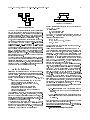
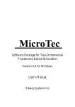
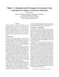
Figure 1: Functionality of PRISMA
approach taken by Mavaddat [2] is focussed on local microcode generation, i.e. mapping pieces of straight-line
code onto a given datapath. The datapath is regarded
as a formal language, and binary code generation is
done by parsing. Langevin and Cerny [3] propose another theoretic method for local microcode generation,
which uses a state machine model of the target datapath. Binary code is derived by traversing state sequences.
Both methods do not support compilation of control
structures and need large amounts of computation time.
The compilers MSSQ and MSSV by Marwedel and Nowak [4, 5] are based on pattern matching between register transfers and hardware structures. Compilation
of data ow as well as control ow structures is supported. Since the complete controller specication is
part of the structural hardware input description, neither the microinstruction format nor instruction restrictions due to encoding or sharing have to be formulated by the user but are detected by the compiler
itself. Microcode compaction and maintenance of temporary cells is restricted to basic blocks resulting in
suboptimal code, but pattern matching as a paradigm
for code generation guarantees fast compilation times.
Thus, the designer is allowed to "play around" with the
target architecture in order to achieve an ecient hardware/software partitioning within an ASIP-based system. The CodeSyn compiler by Paulin [6] uses pattern
matching as well and is tailored towards DSP applications. Pattern matching is done between data/control
ow patterns and instructions. Therefore, the target
hardware description is not pure structural, but is based
on an instruction set specication. This includes the
instruction behaviors and formats as well as the interinstruction restrictions, which all have to be manually
specied by the user. It is stated that full retargetability of CodeSyn required automatic instruction set capture, i.e. the compiler should be able to extract the
possible instructions of a programmable target structure automatically.
EURO-DAC 1994, c 1994 ACM 0-89791-685{9/94/0011 $ 1.50
2
REG1
......
......
.....
......
......
........
........
REG1 = "0011"
and
or
2
....
.....
....
....
.........
.
.
.
.
.
.
..
SHIFTL
.....
......
.....
......
......
........
...........
..
...
....
..
...
...
.
.
.
...
...
...
...
.......
....
..
ACCU
REG2 = "0110"
....
.....
.....
....
........
..........
+
...
...
...
...
...
...
...
...
...
........
.
..
ACCU > 0
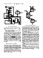
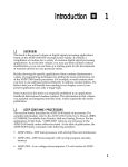
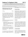
Figure 3: Condition tree
Def: A condition tree is either empty or a triple ct =
Figure 2: Expression tree
The MSSQ compiler [4] generates binary instructions
"on demand" for each statement within the input behavioral description, which results in unnecessary repetitions of operator allocation and data routing within
the target structure. Only branch instructions are allocated in advance during a preallocation phase.
Thus, automatic instruction set extraction from a target hardware description is well motivated. In this paper we present the tool PRISMA (Predetermination
of Instruction Sets of Microprogrammed ASIPs), that
performs this task. PRISMA reads a at RTL netlist
of a programmable hardware structure and extracts the
set of possible microoperations the hardware can perform. Additionally, binary code for disabling unused
storage devices is produced. This information can directly be fed into a RC (g. 1). Note that instruction
set extraction has to be performed only once for each
specic target structure.
The rest of this paper is organised as follows. Sections
2 and 3 describe the tool functionality and the basic internal data structures. The main extraction steps are
presented in sections 4 to 7. Finally, the practical applicability of PRISMA is discussed using several example
datapaths and some conclusions are drawn.
2 Basic denitions
Instruction set extraction from a programmable hardware structure yields a list of microoperations the structure can perform. In order to explain the functionality,
we informally dene some basic notations.
Def: A microoperation is a tuple mo = (t; e; a; c; p),
where
t is a target module (register or memory port)
e is an expression which is assigned to t
a is an address, in case that t is a memory,
otherwise empty
c is a partial control word eld setting,
necessary to execute the assignment
p is a precondition, that has to be fullled to
execute the assignment
An expression e is a tree, whose inner nodes represent
operators (arithmetic, logic, concatenation, comparison) and whose leaves represent storage modules, constants, or external inputs. For instance, the tree in g.
2 represents the term (REG1 SHIFTL 2) + ACCU. The
address a is an expression as well.
The control code c is a string over 0; 1; X; C , where
X denotes a don't care value and C denotes a bit belonging to an immediate constant. The length of c is
equal to the instruction word length. Conditions are
represented by the following data structure:
f
g
(r; ctand; ctor ), where
r is the root
ctand is a condition tree
ctor is a condition tree
The root r of a condition tree is a single equation or
inequation. A condition tree ct is true, if one of the
following conditions holds:
a) ct = empty
b) (r = true) AND (ctand = true)
c) ctor = true
Thus, for example the condition tree shown in g. 3
represents the condition
(REG1 = 0011 AND REG2 = 0110) OR (ACCU > 0)
The equations and inequations within a condition tree
refer to storage contents, module ports, bitstrings or
constants. A precondition p of a microoperation mo is
a condition tree, in which no (in)equation refers to the
instruction memory, since all conditions concerning the
instruction memory are already encoded in the control
code c of mo. The necessity of preconditions can be
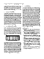
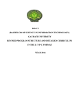
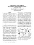
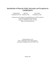
seen in the structure in g. 4, which will serve as a
running example throughout this paper.
In this 8 bit processor, the binary instructions are located in the instruction memory I, whose width is 24
bits. All modules are directly controlled by the instruction word 1 , except the shifter, which is residually
controlled by the contents of the 2 bit shift mode register SM. Depending on the SM contents (00,01,10,11)
the shifter performs a left shift of 0, 2, 4, or 5 bits.
Thus, e.g. moving data from the accumulator accu
to the main memory MAIN with a left shift of 4 requires SM = "10" besides the necessary control codes.
SM = "10" has to be ensured in a machine cycle before
the data transfer is executed, therefore we call this a
precondition. Preconditions always refer to states being reached in an earlier machine cycle.
Two functions for inserting an additional (in)equation
q into a condition tree are dened:
1. OR-Insert inserts a new (in)equation q into a
condition tree ct so that q is an alternative to
fulll ct.
2. AND-Insert inserts a new (in)equation q into a
condition tree ct so that q is necessary in any case
to fulll ct.
Both functions can be extended for inserting a complete
condition tree ct into another tree ct .
In addition to microoperations, we dene special operations for disabling storage modules, i.e. operations
0
1
I.(k:l) denotes an instruction word subrange
EURO-DAC 1994, c 1994 ACM 0-89791-685{9/94/0011 $ 1.50
3
pins.(7:0)
.....
... ...
...
...
..
....
......
.....
....
.
..
......
......
.................
....
....
...
.
.
.
.
.
..
..
.
d0
.....
.... .
.
........
........
...
alumux ctr I.(9)
alumux
...
....
..
.... ...
...... ..... ... ...
....
......
.
.....
.....
.....
...............
....
....
.
....
....
....
I.(23:16)
address
ctr I.(9:8)
alu
....
....
accu ctr I.(15)
....
...
............
shifter ctr
accudrv
I.(15) ctr
MAIN
..
....
.............
....
...
...
....
....
....
....
.....
.... .......
.....
...
... ...
...
SM
ctr
I.(10)I.(1:0)
...
....
...
.
...
............
DATABUS.(7:0)
accucmp
> ?
pcincr
cnd PC
+1 d0
d1
I.(7:0)
pcmux ctr
I.(14:13)
.............
.
..
..
.....
...
..
..
..
.....
.
ctr I.(12:11)
data
..
.............
...
.......... ....
...
............
.
....
..
.........
........
..
....
........
...................................
........
.....
.....
...
..
..
..
...
..
..
.
.
..
.
.
d0
alu
....
....
outp
......... adr
...
I
(7:0)
......
.......
...
..
..
....
..
...
....
..
....
idrv
.....
.....
....
.....
... ........
....
....
..
..
.....
..... ...
.....
........
.... ...
ctr
I.(10)
Figure 4: Example structure
that preserve the current state of a storage module.
Def: A disabling operation is a triple do = (t; c; p),
where
t is the module to be disabled
c is the according partial control word eld setting
p is the necessary precondition
The purpose of PRISMA is to extract the possible microoperations and disabling operations for all storage
modules within a programmable structure described in
a HDL. We assume a microcontrolled structure and
monophase execution. Instruction encoding and bit
sharing are permitted. Note that it is not useful to
extract the set of microinstructions instead of microoperations from a hardware structure, since this would
result in a very large computation time for pairwise
consistency check for all extracted micro- and disabling
operations. Compacting microoperations into a microinstruction can quickly be done by the RC on demand, avoiding consideration of unnecessary microinstructions.
3 Circuit representation
ctr
The HDL read by PRISMA allows description of hardware structures comprising the followingtypes of generic
components: multiplexers, ALUs, decoders, logic gates,
comparators, hardwired constants, busses, registers, memories, tristate drivers, and external pins. RTL netlists
are described by enumeration of all modules together
with their interconnections. One distinguished ROM
within the specication has to be marked as memory
for instructions. The netlist contains the complete controller structure, so that instruction conicts are detected by PRISMA itself.
..............
..
.............
...........
......
..........
...........
........... ..
......................
.........
....
.
.
.
.
.
.
..
..
..
outp
d1
............
....
.............
.....
.....
....
...
............
. ...
....
................................................................
.....
...
...
..
inp
accu
...
....
..
....
.....
......
..
...
....
..
....
d1
0: PASS d1
1: PASS d0
00: d0 + d1 ctr
01: d0 - d1
10: PASS d0
11: PASS d1
0
............
.
.
.......
...........
...
...
......
........
..
..
....
..
...........
... .
..
..
..
.
.
..
..
.
..
.
0: LOAD
1: NOLOAD
.
..
....
.. ....
.. .
ctr
...........
.....
.............
outp
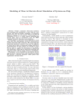
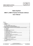
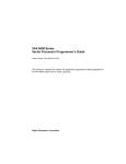
Figure 5: Internal graph structure
The hardware description is parsed into an internal
graph structure, where nodes represent modules and
edges represent interconnections. We assume that modules with variable behaviors have a distinguished control input ctr. The list of possible module behaviors
together with the according control code is attached to
each node. Fig. 5 shows a part of the graph for the
example structure (g. 4).
Graph edges are directed opposite to the data ow
direction. The behavior tables are shown within the
nodes, e.g. the ALU alu performs four dierent operations on its data inputs d0 and d1, depending on the
control code ctr (00,01,10,11): addition, subtraction,
and passing d0 resp. d1 unchanged to the output outp.
The multiplexer alumux only performs PASS operations
on its inputs. The register accu stores a new value at
its input when its control input is 0, otherwise preserves its state. Modules without a control input have
a behavior table consisting of a single entry. Busses are
represented as dummy modules only supporting a PASS
operation. Every bus driving module has to have a
TRISTATE operation. All storage modules are assumed
to change their state at the same clock edge if they are
enabled.
A restriction is, that modules may have only one output
port, except multiport memories. This restriction can
be circumvented by splitting the output into several
subranges.
The internal graph structure is similar to the one proposed in [4] and allows quickly backtracking data sources
within the structure. This is essential for the tasks described in the following two sections.
EURO-DAC 1994, c 1994 ACM 0-89791-685{9/94/0011 $ 1.50
4
4 Extraction of expressions
As dened in section 2, every microoperation assigns
an expression e to a target storage module t. Each assignment in general requires several conditions to be
fullled, e.g. (see g. 4) loading memory MAIN at a
certain address with
the accumulator contents shifted
left by 4 requires2 :
shifter.ctr = "10" (perform left shift of 4)
accudrv.ctr = "1" (accudrv drives the databus)
MAIN.ctr = "00" (MAIN reads from databus)
idrv.ctr = "0" (idrv is in TRISTATE mode)
Since these conditions can be represented by a condition tree, we can think of every expression e to have
an associated condition tree cte . In order to extract
all microoperations systematically, at rst all expressions with the associated condition trees for each storage module input are extracted. This is the purpose of
the function
FindExpressions : module list of pairs (e; cte )
yielding a list of expressions e a module can deliver at
its output port, assuming condition cte is fullled. Due
to the underlying graph structure, FindExpressions can
be implemented recursively. Recursion stops when a
leaf module, (i.e. storage, HW constant or external
input) is reached. The expression delivered by a leaf
module is simply its contents resp. value. For non-leaf
modules, FindExpressions backtracks the data ow and
possible operations within the structure, while building
up the according condition trees on-the-y. Necessary
conditions are AND-inserted, whereas alternatives are
OR-inserted in the current condition tree. When FindExpressions is called for a bus, it ensures that all bus
drivers unused for a certain expression are in TRISTATE
mode in order to avoid bus conicts. Recursion also
must terminate when cyclic paths are detected, e.g. due
to bus exchanges.
We consider a call to FindExpressions for module pcmux,
which determines the next state of the program counter
PC. The pcmux has the behavior table
00: PASS d0
01: PASS d1
1X: IF cnd THEN PASS d1 ELSE PASS d0
i.e. control codes 00 resp. 01 pass the inputs d0 resp.
d1 to the output, and control codes 10 and 11 pass one
input depending on the condition input cnd. FindExpressions(pcmux) calls itself recursively for the predecessor modules pcincr and I and yields the following
results:
7!
No. Expression Condition
1
PC + 1 pcmux.ctr = "00" OR (pcmux.ctr =
"1X" AND pcmux.cnd = "0")
2 I[PC].(7:0) pcmux.ctr = "01" OR (pcmux.ctr =
"1X" AND pcmux.cnd = "1")
FindExpressions also takes into account semantical in-
formation about the operations performed by the different modules. This is e.g. done by exploiting left and
right neutral elements of operations, like 0 for addition
and disjunction or 1 for multiplication and conjunction.
2 The notation < m >.< p > denotes port < p > of module
< m >.
Thus, an ALU performing subtraction on two inputs a
and b implicitly has a virtual PASS operation, presuming the constant 0 can be allocated at input b. Exploiting virtual operations leads to an extended set of
microoperations which in turn provide higher degrees
of freedom for a compiler.
Using FindExpressions as a subroutine, all expressions
assignable to any storage module can be extracted in
the following manner:
PROCEDURE ExtractAllExpressions(target storage module t);
BEGIN
m inp := module connected to the input port of t;
L inp := FindExpressions(m inp);
FOR EACH (e inp,ct inp) IN L inp DO
IF (t is an addressable memory)
THEN
m adr := module connected to the address port of t;
L adr := FindExpressions(m adr);
FOR EACH (e adr,ct adr) IN L adr DO
ct := empty condition tree;
AND-Insert(ct,"control code for LOAD operation of t");
AND-Insert(ct,ct inp);
AND-Insert(ct,ct adr);
ATTACH (e inp,e adr,ct) TO t;
OD
ELSE (* m is a single register *)
ct := empty condition tree;
AND-Insert(ct,"control code for LOAD operation of t");
AND-Insert(ct,ct inp);
ATTACH (e inp,ct) TO t;
FI
OD
END;
Procedure ExtractAllExpressions is called for each storage module. As a result of this phase, each register has
been attached a list of expression/condition tree pairs
that represent possible assignments to it. For memory
modules, additionally all address expressions have been
generated together with the according condition trees.
A triple (e inp,e adr,ct) attached to memory M means
M[e adr] := e inp if ct is true.
All single conditions are equations of the type "module input port = bitstring". In order to determine
whether a condition can be fullled and thus results
in a valid microoperation, the bitstrings have to be allocated. This task is subject of the following section.
5 Constant allocation
The next step is to expand the condition trees found
in the expression extraction phase. A condition tree
is called expanded, when all its single conditions only
refer to storage contents instead of module ports. For
instance the condition "shifter.ctr = 10" can be expanded to "SM = 10" in the example structure. Condition tree expansion requires constant allocation at
module ports. This is the purpose of the function
Allocate : module bitstring condition tree
computing a condition tree that forces a module to
produce a given bitstring at its output port3 . If the
module cannot provide the required constant, Allocate
7!
3 Actually, PRISMA also considers port subranges during extraction. This has been left out in the paper for sake of simplicity.
EURO-DAC 1994, c 1994 ACM 0-89791-685{9/94/0011 $ 1.50
5
returns an "IMPOSSIBLE" value. Similar to FindExpressions the function Allocate recursively backtracks
data ow through the graph structure until leaf modules are reached. In general, constants are allocated at
storages, HW constants or decoders. Semantical information about operations is taken into account as well,
e.g. an ALU can (among other alternatives) produce a
constant c by computing c + 0 or c AND 11...11. Note
that "perfect" constant allocation is practically impossible due to the large number of alternatives that may
arise (consider, for instance, the number of versions to
generate a certain 32 bit constant by addition). Thus,
there cannot exist a tool for extracting all possible microoperations from any arbitrary target structure. Expanding a condition tree resulting from expression extraction is done by the following procedure.
PROCEDURE ExpandConditionTree(condition tree ct);
BEGIN
FOR EACH node "module.port = bitstring" IN ct DO
m = module whose output is connected to module.port;
ct' = Allocate(m,bitstring);
IF ct' != IMPOSSIBLE
THEN REPLACE node BY ct';
FI
OD
END;
The structure of condition trees can be exploited, e.g. if
expansion of a node fails, all nodes in its AND-subtree
can be skipped. Calling ExpandConditionTree for the
two trees in the previous example (see section 4), one
obtains:
No.
1
2
Expression
PC + 1
I[PC].(7:0)
Expanded condition
I[PC].(14:13) = "00" OR (I[PC].(14:13)
= "1X" AND accu <= 0)
I[PC].(14:13) = "01" OR (I[PC].(14:13)
= "1X" AND accu > 0)
ExpandConditionTree is called for each condition tree
produced during expression extraction. Therefore, nally all conditions only refer to the distinguished instruction memory or to other storages. This allows
splitting the conditions into control word eld settings
and preconditions.
6 Microoperation generation
In order to transform the previously extracted register/memory assignments into microoperations as dened in section 2, the subroutine
Split : condition tree list of pairs (c; ct)
is used, where c is a partially initialised instruction
word and ct is a condition tree only comprising preconditions. Split performs several subtasks:
a) Check whether a condition refers to the instruction
memory or to another storage. If the instruction memory is referenced, set the according bits in c and eliminate the condition from the tree. Otherwise keep this
condition as a precondition.
b) Check for instruction conicts of conditions sharing
subranges of the instruction word.
c) Check whether the remaining precondition tree is
consistent, i.e. all conditions to be fullled concurrently
are pairwise compatible.4
Calling Split for the previous example trees results in
7!
4 Since occurence of cyclic inconsistencies in practical structures is very unlikely, only pairwise compatibility is checked.
No. Expression (partial instruction, precondition)
1
PC + 1 (xxxxxxxxx00xxxxxxxxxxxxx,
empty)
(xxxxxxxxx1xxxxxxxxxxxxxx,
"accu <= 0")
2 I[PC].(7:0) (xxxxxxxxx01xxxxxxxxxxxxx,
empty)
(xxxxxxxxx1xxxxxxxxxxxxxx,
"accu > 0")
yielding two alternatives for assigning each of the two
expressions to register PC.
All register/memory assignments (see section 4) are
transformed into microoperations. Assuming Split computes a list ((c1 ; ct1); : : :; (cn; ctn)) for the condition
tree ct of an assignment (e inp,ct) to a target register
t, the set of microoperations moi = (t; e inp; ; ci; cti) is
constructed for this assignment. Memory assignments
are transformed accordingly into microoperations with
a non-empty address eld.
In order to avoid unnecessary restrictions, all microoperations having the same target and the same expression/address are heuristically compacted, i.e. if
the preconditions are compatible and the instruction
words dier only in one bit bi, two microoperations
can be replaced by one with bi = X. After compaction
the extraction of microoperations is nished. For the
example structure, PRISMA nds:
4 Operations for register PC
1 operation for register SM
10 operations for register accu
5 operations for memory MAIN
The output including bit range information in case of
register PC is:
MICROOPERATIONS FOR REGISTER PC:
(1) Expression: (PC.(7:0) + 1).(7:0)
Preconditions: <empty>
Code:
24 20 16 12
8
4
0
-|---|---|---|---|---|---|
xxxxxxxxx00xxxxxxxxxxxxx
(2) Expression: I[PC.(7:0)].(7:0)
Preconditions: <empty>
Code:
24 20 16 12
8
4
0
-|---|---|---|---|---|---|
xxxxxxxxx01xxxxxCCCCCCCC
(3) Expression: I[PC.(7:0)].(7:0)
Preconditions: accu.(7:0) > 0
Code:
24 20 16 12
8
4
0
-|---|---|---|---|---|---|
xxxxxxxxx1xxxxxxCCCCCCCC
(4) Expression: (PC.(7:0) + 1).(7:0)
Preconditions: accu.(7:0) <= 0
Code:
24 20 16 12
8
4
0
-|---|---|---|---|---|---|
xxxxxxxxx1xxxxxxxxxxxxxx
There are two alternative operations (2 and 3) for loading the program counter immediately from I. Operation (3) only needs bit 14 of the instruction word to
be set to 1, but requires accu to be greater zero from
a previous instruction cycle. A RC might regard this
as a conditional jump operation, whereas operation (2)
could serve as an unconditional jump.
EURO-DAC 1994, c 1994 ACM 0-89791-685{9/94/0011 $ 1.50
When subranges of the instruction word occur in expressions, the according bits in the control code are
symbolically set to "C" to indicate that the instruction
provides an immediate constant at these bits, and thus
a restriction exists for setting these bits in microoperations to be executed concurrently.
7 Storage disabling
When several microoperations are packed into one microinstruction, unused storage modules must remain
unchanged. Therefore, PRISMA also extracts disabling
operations for each register or memory port. This task
is very similar to extraction of microoperations. All
(expression, precondition) pairs are computed that guarantee NOLOAD operations for each storage. Additionally,
in case of registers, versions are extracted that force a
register to store its previous value, i.e. PRISMA looks
for cyclic paths within the structure. For instance, the
accu can preserve its state by setting instruction bit 15
to 1 ("NOLOAD", see g. 4 and 6), or by setting instruction bit 15 to 0 ("LOAD") and bits (9:8) to 10 ("PASS
d0" via alu). Generating these additional disabling operations can provide more alternatives for a compiler to
select from during code compaction.
8 Experimental results
PRISMA has been implemented with about 10,000 lines
of C++ code on a Sun SPARCstation 10. It has been
applied to several target structures, among them the
datapaths mentioned in [3] (di) and [5] (mssv), and
partial datapaths of the TMS320 DSP family [7] and of
the ADSP2101 signal processor [8]. Since no information about the internal controller structure is provided
for TMS and ADSP, an arbitrary VLIW controller has
been added to these structures in order to permit extraction.
structure
example
di
E1000
ADSP
mssv
mssq
TMS
# modules
15
23
18
43
8
13
29
# -OPs
20
79
48
746
53
127
545
CPU sec
0.57
0.95
0.66
305
0.90
13.76
378
Table 1: Experimental results
The results shown in table 1 indicate that instruction
set extraction is feasible even for larger realistic structures. Runtime grows rapidly with the number of extracted microoperations due to the compaction phase.
Time for compaction could be reduced by pre-sorting
the extracted operations into several groups according
to their expressions and compaction only within each
group, but this is only an implementation issue. The
number of extracted microoperations itself is mainly inuenced by features of the structural model: the number of RT level modules, the number of dierent behaviors per module, and the chaining degree within the
structure. The number of resulting microoperations is
only reduced by instruction word restrictions, such as
bit sharing (see e.g. alumux and alu in g. 4).
6
9 Conclusions
With ASIPs emerging as a new important means of
DSP system implementation, CAD tool support becomes necessary for software development for these systems. Retargetable compilers that map behavioral descriptions onto specic structures by exploiting complex instruction sets with high degree of potential parallelism have been proposed to solve this problem. Pattern matching has been identied as one key technique
in this context [5, 6]. Matching is performed between
data/control ow patterns in the behavioral description and RT patterns in the hardware structure. The
latter can be extracted from the hardware descriptions
automatically, resulting in full compiler retargetability. A prototype tool for instruction set extraction was
presented in this paper, which provides a convenient
interface between compiler and target structure, since
the possible patterns of a given structure can be computed in advance and be stored in a database. Restrictions arising from the controller structure are already
detected in this phase. During the steps of binary code
generation (allocation and code compaction), the compiler can rely on this pattern database rather than on
the RTL structure, permitting a higher level of abstraction. Experiments with realistic structures proved feasibility of instruction set extraction. Future work will
include extending the structure domain towards modules with multi-cycle operations.
References
[1] P.G.Paulin: DSP Design Tool Requirements for the
Nineties: An Industrial Perspective, 6th International
High Level Synthesis Workshop, 1992
[2] M.Mahmood, F.Mavaddat, M.I.Elmasry: Experiments
with an Ecient Heuristic Algorithm for Local Microcode Generation, Proc. International Conference on
Computer Design (ICCD), 1990, pp. 319-323
[3] M.Langevin, E.Cerny: An Automata-Theoretic Approach to Local Microcode Generation, Proc. European Design and Test Conference(EDAC), 1993, pp.
94-98
[4] L. Nowak, P. Marwedel: Verication of Hardware
Descriptions by Retargetable Code Generation, Proc.
26th Design Automation Conference, 1989, pp.441-447
[5] P.Marwedel: Tree-Based Mapping of Algorithms to
Predened Structures, Proc. International Conference
on Computer-Aided Design (ICCAD), 1993, pp. 586593
[6] C.Liem, T.C.May, P.G.Paulin: Instruction Set Matching and Selection for DSP and ASIP Code Generation,
to appear in: Proc. European Design and Test Conference (EDAC), 1994
[7] TMS320C2x User's Guide, Rev. B, Texas Instruments,
1990
[8] ADSP2101/2102 User's Manual (Architecture), Analog
Devices, 2nd Edition, 1991