1
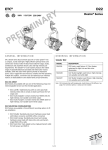
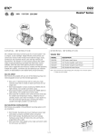
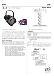
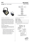
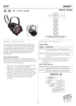
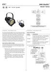
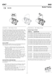
ETC®
D40XTI™
Desire™ Series
G e n e r a l i n f o r m at i o n
O r d e r i n g i n f o r m at i o n
ETC’s Desire D40XTI brings the amazing control of the seven-color x7
Color System™ to your permanent application. With its IP66 rating,
this fixture is ready for installation inside or outside - wherever you
need it. The Selador® x7 Color System produces the widest range
of spectrally-balanced saturated and tinted color choices available.
The D40XTI offers a rugged die-cast enclosure; noiseless fan-free
operation; and multiple lens options that can be changed
on site.
Selador D40XTI
Model
Description
SELD40XTI-V
D40 Vivid wash fixture
SELD40XTI-L
D40 Lustr+ front light wash fixture
SELD40XTI-F
D40 Fire special wash fixture
SELD40XTI-I
D40 Ice special wash fixture
SELD40XTI-H D40 Studio HD wash fixture
D40XTI LED Array Options
D40XTI fixtures are based on the x7 Color System, which uses seven
different LED colors to achieve true, usable broad-spectrum color.
The D40XTI luminaire is available with any one of the following color
arrays to best suit the intended application.
SELD40XTI-D D40 Studio Daylight wash fixture
SELD40XTI-T
D40 Studio tungsten wash fixture
Note: D40XTI luminaires ship with hanging yoke, attached leads and a datatermination board. C-clamp, lenses or other accessories are not included.
• D40XTI Vivid™ – Best all-around use as a color-changing wash fixture
• D40XTI Lustr+™ – Optimized with six colors plus high-intensity white LEDs to create an ideal frontlight wash fixture; full
range color, with an emphasis on lighter colors and white
• D40XTI Ice™ – Uses cool x7 colors to provide extra-high brightness color in the blue end of the spectrum
• D40XTI Fire™ – Uses warm x7 colors to provide extra-high brightness color in the red end of the spectrum
•D40XTI Studio HD – Combines warm-white and cool-white LEDs with five carefully-chosen x7 LED colors, to fill in white LED spectral apps with variable color-temperature mixing. for the richest variable white light possible in an LED fixture
Also available in the following static-white arrays:
• D40XTI Studio Daylight – Contains forty 5600K LEDs for high-intensity, non-variable cool-white output
• D40XTI Studio Tungsten – Contains forty 3000K LEDs for high-intensity, non-variable warm-white output
1 of 10
ETC®
D40XTI™
Desire™ Series
S p e c i f i c at i o n s
S p e c i f i c at i o n s
General
• Easy setup via any RDM device such, as ETC Gateways
and Gadget
• Color-mixing arrays have 40 LEDs for variable color washes
• Static-color arrays have 40 LEDs for white-light washes
• ETL Listed to UL1598
• IP66-rated for exterior, wet-location use
• Data-termination board for easy installation (included)
Physical
• Rugged die-cast, all-metal housing
• Accessory ring for installation of secondary lenses
• Available in black (standard), white, silver (optional) or custom colors (contact factory)
• Hanging yoke standard.
• Cable diameter: Power 0.36”/ Data 0.34”
• Effective Projected Area (EPA): 0.74
Electrical
• 100VAC to 240VAC 50/60 Hz universal power input
• Waterproof, 72” outdoor-rated power-lead
• Up to 10 fixtures (15A max) may be fed on the same circuit
• Requires power from a non-dim source
LED*
• 50,000 hour-LED life (50,000 hours to 70% intensity)
• 40 Luxeon® Rebel LED emitters
• Studio Daylight and Studio Tungsten use Rebel ES white-light
emitters for higher output
Thermal
• Ambient operating temperature of -4° to 104°F (-20° to 40°C)
• Active electronic thermal management for
droop-free operation
• Noiseless, fan-free convection-cooling for acoustically
sensitive installations
• Fixture is designed for continuous operation up to 104°F
(40°C) ambient temperature and requires free flow of air
around fixture housing
A D D ITIONAL OR D ERIN G INFORMATION
Fixture Accessories
*See additional LED notes on page three
Color
• Exclusive x7 Color System™ seven-color LED array
• Broad-spectrum color interacts seamlessly with
conventional sources
• Beautifully illuminates skin tones and objects for natural appearance and high color-rendering
• Exclusive red-shift option emulates tungsten dimming performance (not available on static-white fixtures)
• Studio HD array uses warm and cool white light emitters with
additional deep-color emitters
• Studio Tungsten and Studio Daylight provide good color
rendering at very high brightness
Optical
• Primary field angle of 17° and beam angle of 8°
• Secondary lenses available for multiple beam-spread options
• Lenses must be ordered separately
• Refer to accessories chart for available lenses
Control
• DMX512 In and Thru via termination board (included)
• See DMX Control Table for operation modes
• 15-bit virtual dimming engine provides smooth, high-quality
theatrical fades and minimizes color-shift during dimming
• RDM functionality for address and setting changes
2 of 10
MODEL
DESCRIPTION
D40XTIWM
Wall-Mount Kit (black)
D40XTIWM-1
Wall-Mount Kit (white)
D40XTISPM
Single Pole-Mount Kit (black)
D40XTISPM-1
Single Pole-Mount Kit (white)
D40XTIDPM
Double Pole-Mount Kit (black)
D40XTIDPM-1
Double Pole-Mount Kit (white)
D40XTIL
Egg Crate (black)
D40XTIL-1
Egg Crate (white)
D40XTIHH
Half Shield (black)
D40XTIHH-1
Half Shield (white)
400CC
C-Clamp (does not ship with fixture)
400SC
Safety Cable (32”)
ETC®
D40XTI™
Desire™ Series
a dd i t i o n a l o r d e r i n g i n f o r m a t i o n
N o t e s a b o u t LE D l u m i n a i r e s
Secondary Lens Options
All LED sources experience some reduction of light output and some
color shift over time. LED output will vary with thermal conditions.
Thermal conditions can be affected by ambient temperatures and
orientation. See the D40 Ambient Temperature and Power Budgeting
Guide for more details. Based on the LED manufacturer’s B50 L70
specification, a Selador luminaire will achieve ~70% of its initial
output after 50,000 hours of typical usage. In individual situations,
LEDs will be used for different durations and at different levels.
This can eventually lead to minor alterations in color performance,
necessitating slight adjustments to presets, cues or programs.
MODEL
DESCRIPTION: The following lenses are cut
for D40XTI™ fixtures and create round, linear
or oblong field patterns as described below.
These lenses are not for use in Selador® Classic
(Vivid-R™, Lustr®, Paletta™, etc.) fixtures.
Narrow
Linear Field
Note: This is the same material as Selador
Classic lenses
D40XTI-LVN
Very Narrow lens
D40XTI-LN
Narrow lens
D40XTI-LM
Medium lens
D40XTI-LW
Wide lens
D40XTI-LXW
Extra Wide lens
Round Field
Any one of the following round lenses may be
installed permanently in the fixture at the factory
as a special order
D40XTI-RVN
Very Narrow lens (round field)
D40XTI-RN
Linear lenses
may be
combined
to create
desired field
size
C RI a n d C Q S RATIN G S
Desire fixtures were evaluated for CRI and CQS performance using
measured output spectrum and optimized mix solutions for a best
spectral match to black body sources at 3200K and 5600K.
Fixture
CRI
CQS
Color
Fidelity
Duv
Narrow lens (round field)
D40 Vivid™ at 3200K
87
89
89
0.000
D40XTI-RM
Medium lens (round field)
D40 Vivid at 5600K
90
92
92
0.000
D40XTI-RW
Wide lens (round field)
D40 Lustr+ at 3200K
86
88
88
0.000
D40XTI-RXW
Extra Wide lens (round field)
D40 Lustr+ at 5600K
93
92
90
0.000
D40 Studio HD at 3200K
89
90
91
0.000
Narrow lens (oblong field)
D40 Studio HD at 5600K
92
94
94
0.000
D40XTI-OM
Medium lens (oblong field)
71
70
69
0.001
D40XTI-OW
Wide lens (oblong field)
D40 Studio Daylight at
5600K
D40 Studio Tungsten at
3000K
86
86
86
0.001
™
Oblong Field
D40XTI-ON
http://www.etcconnect.com/docs/docs_downloads/
miscdocs/Desire_vs_PAR_EA_revB.pdf
Typical Lens-Field Profiles
Narrow Linear
Round
Oblong
Power Consumption at Full Intensity
Model
Voltage
(V)
Current
(A)
Watts
D40XTI
120 / 240
1 / 0.5
110
All D40XTI Studio luminaire versions provide excellent color rendering
to the eye, particularly at higher color-temperature settings, such
as 5600K. In most cases, the Duv is 0.000. A Duv rating of 0.000
indicates that the color mix used is exactly on the black body line,
with no green or magenta tint.
Notes to Videographers:
• All Desire fixtures use Luxeon Rebel ES emitters specified
by the strictest binning standards. However, on-camera LED
response varies with different cameras and settings. Daylight
LEDs can appear slightly greener than other 5600K sources
on camera.
• Fixtures with non-variable, single-color daylight arrays, such as
Studio Daylight, may use standard color-corrrection filters
(Rosco 3314, Rosco 3316 or similar) to achieve the desired
on-camera result.
• Camera tests using your specific setup are recommended to
determine the best configuration.
3 of 10
ETC®
D40XTI™
Desire™ Series
control options
control options
User settings on D40XT fixtures allow multiple operational modes and
settings for either console operation via DMX protocol or stand-alone
operation. The expanded LCD display provides easy navigation to all
possible settings and choices. Some of the setting options are:
• Multiple DMX options, ranging from a simple RGB
profile – which effectively controls all seven LED colors via
three channels – to nine-channel ‘direct’ color and
intensity control
• Multiple dimming curve options
• Preset colors and sequences for stand-alone (no console
required) operation
• White-point selection: white light and color behavior based
on a specific color-temperature white light, such as 3200K
or 5600K
• Loss of data behavior options: instant off, hold last look for
two minutes, etc.
• Output modes: Three output options that offer the user a
choice between maximum output and maximum consistency
See the user manual for a complete explanation of all of the control
settings and options for the D40XTI
DMX Input Channel Profiles
DMX
Profile
DMX
Channels
Channel
Assignments
Notes
Direct
9
1 – Red
2 – Orange
(white if Lustr+)
3 – Amber
4 – Green
5 – Cyan
6 – Blue
7 – Indigo
8 – Intensity
9 – Strobe
Direct control of each individual
color with a separate masterintensity channel. Color
calibration of LEDs is not active
in this mode. The nine-channel
profile will produce the highest
quality color crossfades.
HSI
5
1 – Hue (coarse)
2 – Hue (fine)
3 – Saturation
4 – Intensity
5 – Strobe
High resolution hue (twochannels), saturation, and
intensity control. HSI mode will
produce color crossfades around
the color space.
HSIC
6
1 – Hue (coarse)
2 – Hue (fine)
3 – Saturation
4 – Intensity
5 – Strobe
6 – Color Point
(CCT)
High-resolution hue, saturation
and intensity control as above,
with the addition of a color
point channel to adjust the
color temperature of the fixture
in both white light and color.
Color cross-fade performance is
the same as EHSI.
RGB
5
(Ch. 4
not used)
1 – Red
2 – Green
3 – Blue
4 – n/a
5 - Strobe
Effectively addresses all seven
colors via three channels of
control. RGB profile will
produce medium-quality color
crossfades.
1 – Intensity
2 – Color Point
(CCT)
3 – Tint
Controls fixture as a white light
unit. If no DMX, for example
console input- is present, the
fixture can be adjusted for these
three parameters on the U/I at
the back of the unit.
Quick Setups
To assist in managing the numerous control and fixture behavior choices, five
combinations of operational settings are available to quickly get started. These
settings are specifically created for different applications and are easily accessible at
the fixture display. Each setting can then be modified as required to take advantage
of all of the possible control features.
Setting
Title
Profile
General
Direct
Factory default:
For general-purpose use
,including interior architectural
applications.
• Standard dimming curve
• Regulated output for
color consistency
Stage
HSI
Plus 7
Enabled
Theatrical lighting:
Duplicates the color and
dimming behavior of tungsten
stage lighting fixtures.
• Incandescent dimming
curve
• Regulated output for
color consistency
• 3250K white-point
setting
HSI
Exterior architectural lighting:
Provides a high degree of
color consistency in high
ambient-temperature
environments.
• Standard dimming curve
• Protected output
• 3200K white-point
setting
Event lighting:
Enables quickest response,
simple RGB control and strobe
channel for maximum effect
usage.
• Quick dimming curve
• Boost mode for
maximum intensity
• 5600K white-point
setting
Video/film lighting:
Enables three-parameter
control of white light
(intensity, white point and
tint) via DMX from console
or from fixture display – no
console required.
• Linear dimming curve
• Regulated output mode
for color consistency
XT Arch
High
Impact
RGB
Studio
Studio
Description
Typical Features*
Studio
3
Additional profile options
Plus 7
Seven additional color control channels are
available in RGB, HSI, HSIC, and Studio profile
settings. For example, HSI with ‘Plus 7’ enabled
becomes a 14-channel profile:
1 – Hue (coarse)
2 – Hue (fine)
3 – Saturation
4 – Intensity
5 – Strobe
6 – n/a
7 – Plus 7
Control on/off
8 – Red
9 – Orange
(white if Lustr+)
10 – Amber
11 – Green
12 – Cyan
13 – Blue
14 – Indigo
Strobe
*See user manual for complete list of features for each Quick Setup.
4 of 10
The desired color and intensity
is achieved by using the HSI or
RGB channels.
Placing channel seven at a value
over 51% gives the fixture a
14-channel profile.
Channels 8-14 represent the
native colors of the fixture and
allow the operator to adjust
individual color channels to fine
tune the color output.
Variable strobe control: 0% is no strobe. The
fixture output will strobe more rapidly as the strobe
channel value approaches 100%.
ETC®
D40XTI™
Desire™ Series
control options
control options
Studio Daylight and Studio Tungsten (only)
Quick Setups
DMX Input Channel Profiles
Setting
Title
Profile
Studio
Studio
Simple mode for linear
intensity control
• Linear dimming curve
• Regulated output for
intensity stability
Single
Channel
Direct
For general purpose
architectural use
• Standard dimming
curve
• Regulated output for
consistency
Stage
Direct
Matches conventional
luminaire performance
• Incandescent dimming
curve
• Regulated output
Description
Typical Features*
5 of 10
DMX
Profile
DMX
Channels
Channel
Assignments
Studio
3
1 – Intensity
2 – Strobe
3 – N/A - only
used in D60
Direct
3
1 – Intensity
2 – Strobe
3 – N/A - only
used in D60
Notes
Control of parameters is also
enabled from the luminaire’s user
interface. No console required.
ETC®
D40XTI™
Desire™ Series
ph o t o m e t r i cs
Cosine Candela Plot
D40XTI Vivid™
Degree
Candela
Field
Lumens
Beam
Lumens
Lumens
Per Watt
Boost - Cold
17˚
101,900
2,540
1,200
26.7
Regulated
17˚
87,200
2,150
1,020
26.5
100000
80000
Candela
Mode
120000
X
60000
Y
40000
Metric Conversions: For Meters, multiply feet by 0.3048
For Lux, multiply foot-candles by 10.76
20000
0
-15
-10
-5
0
5
10
15
17˚
Iso-Illuminance Diagram
Field Angle
8˚
Beam Angle
Degrees
(Flat Surface Distribution)
Y
Throw Distance (d)
10.0’
3.0m
15.0’
4.6m
20.0’
6.1m
25.0’
7.6m
319’
97m
Field Diameter
3.1’
0.9m
4.6’
1.4m
6.2’
1.9m
7.7’
2.3m
– Illuminance (fc)
1,1019
453
255
163
1
Illuminance (lux)
10,968
4,875
2,742
1,755
10.76
10%
50%
% illuminance
foot-candle
or lux
X
For field diameter at any distance, multiply distance by 0.308
For beam diameter at any distance, multiply by 0.145
.056
D40XTI Lustr+™
Mode
.111
.167
Cosine Candela Plot
Degree
Candela
Field
Lumens
Beam
Lumens
Lumens
Per Watt
120000
100000
17˚
121,500
2,980
1,450
30.3
Regulated
17˚
109,100
2,680
1,300
29.8
80000
Candela
Boost - Cold
X
60000
Metric Conversions: For Meters, multiply feet by 0.3048
For Lux multiply foot-candles by 10.76
Y
40000
20000
0
-15
-10
-5
0
5
10
15
17˚
Field Angle
8˚
Beam Angle
Degrees
Iso-Illuminance Diagram
(Flat Surface Distribution)
Y
Throw Distance (d)
10’
3.0m
15.0’
4.6m
20.0’
6.1m
25.0’
7.6m
348’
106m
Field Diameter
3.0’
0.9m
4.5’
1.4m
6.0’
1.8m
7.5’
2.3m
– Illuminance (fc)
1,215
540
304
194
1
Illuminance (lux)
13,078
5,813
3,270
2,093
10.76
10%
50%
X
% illuminance
foot-candle
or lux
For field diameter at any distance, multiply distance by 0.301
For beam diameter at any distance, multiply by 0.145
.056
6 of 10
.111
.167
ETC®
D40XTI™
Desire™ Series
Cosine Candela Plot
ph o t o m e t r i cs
120000
D40XTI Fire™
Mode
100000
Degree
Candela
Field
Lumens
Beam
Lumens
Lumens
Per Watt
80000
40000
Boost - Cold
17˚
94,900
2,540
1,200
28.7
Regulated
17˚
82,500
2,220
1,040
26.5
X
60000
Y
20000
0
-15
Metric Conversions: For Meters, multiply feet by 0.3048
For Lux, multiply foot-candles by 10.76
-10
-5
0
5
10
15
17˚
(Flat Surface Distribution)
Field Angle
8˚
Beam Angle
Iso-Illuminance Diagram
Y
10%
Throw Distance (d)
Field Diameter
10.0’
3.0m
15.0’
4.6m
20.0’
6.1m
25.0’
7.6m
308’
93m
3.2’
1.0m
4.8’
1.5m
6.4’
1.9m
8.0’
2.4m
– Illuminance (fc)
949
422
237
152
1
lluminance (lux)
10,215
4,540
2,554
1,634
10.76
50%
% illuminance
foot-candle
or lux
X
For field diameter at any distance, multiply distance by 0.318
For beam diameter at any distance, multiply by 0.148
.056
D40XTI Ice™
Mode
Degree
Candela
Field
Lumens
Beam
Lumens
Lumens
Per Watt
Boost - Cold
17˚
70,900
1,830
890
18.1
Regulated
17˚
63,200
1,630
790
18.0
.111
.167
Cosine Candela Plot
140000
120000
100000
80000
Metric Conversions: For Meters, multiply feet by 0.3048
For Lux, multiply foot-candles by 10.76
X
Y
60000
40000
22˚
0
-15
Field Angle
11˚
Beam Angle
20000
-5
0
5
10
15
Iso-Illuminance Diagram
Throw Distance (d)
10.0’
3.0m
15.0’
4.6m
20.0’
6.1m
30.0’
9.1m
266’
81m
Field Diameter
3.1’
0.9m
4.6’
1.4m
6.2’
1.9m
9.3’
2.8m
– Illuminance (fc)
709
315
177
79.78
1
7,632
3,392
1,908
848
10.76
Illuminance (lux)
-10
(Flat Surface Distribution)
Y
10%
50%
% illuminance
foot-candle
or lux
X
For field diameter at any distance, multiply distance by 0.310
For beam diameter at any distance, multiply by 0.147
Throw Distance Multiplier (TDM)
To determine the distance from the center of the beam (Origin) to a certain illuminance level at a particular
distance, multiply the desired throw distance by the TDM desired on the Iso-Illuminance diagram.
Throw Distance (TD) x Throw Distance Multiplier (TDM) = Distance from the Origin (DfO) (distance from the
center of the beam)
Example: 25 feet (TD) x 0.047 (TDM) = 1.175 feet from center of beam (DfO)
For illumination with any lamp, multiply the candlepower of a beam spread by the multiplying factor (mf) shown for
that lamp.
To determine illumination in foot-candles or lux at any throw distance, divide candlepower by distance squared.
7 of 10
.056
.111
.167
ETC®
D40XTI™
Desire™ Series
Cosine Candela Plot
ph o t o m e t r i cs
120000
D40XTI Studio HD
Mode
100000
Degree
Candela
Field
Lumens
Beam
Lumens
Lumens
Per Watt
Boost - Cold
17˚
121,900
3,120
1,410
30.9
Regulated
17˚
109,500
2,780
1,260
30.9
80000
X
60000
Y
40000
20000
0
-15
-10
-5
0
5
10
15
Metric Conversions: For Meters, multiply feet by 0.3048
For Lux, multiply foot-candles by 10.76
17˚
(Flat Surface Distribution)
Field Angle
8˚
Beam Angle
Iso-Illuminance Diagram
Y
10%
Throw Distance (d)
10.0’
3.0m
15.0’
4.6m
20.0’
6.1m
25.0’
7.6m
349’
106m
Field Diameter
3.1’
1.0m
4.7’
1.4m
6.3’
1.9m
7.8’
2.4m
– Illuminance (fc)
1,219
542
305
195
1
lluminance (lux)
13,121
5,832
3,280
2,099
10.76
50%
% illuminance
foot-candle
or lux
X
For field diameter at any distance, multiply distance by 0.313
For beam diameter at any distance, multiply by 0.143
.056
D40XTI Studio Daylight
Mode
Degree
Candela
Field
Lumens
Beam
Lumens
Lumens
Per Watt
Boost - Cold
22˚
125,700
5,380
2,850
52.5
Regulated
22˚
125,350
3,440
1,820
56.3
.111
.167
Cosine Candela Plot
140000
120000
100000
80000
Metric Conversions: For Meters, multiply feet by 0.3048
For Lux, multiply foot-candles by 10.76
X
Y
60000
40000
22˚
0
-15
Field Angle
11˚
Beam Angle
20000
-10
-5
0
5
10
15
Iso-Illuminance Diagram
(Flat Surface Distribution)
Throw Distance (d)
10’
3.0m
15’
4.6m
20’
6.1m
25’
7.6m
354’
108.1m
Field Diameter
3.9’
1.2m
5.8’
1.8m
7.8’
2.4m
9.7’
3.0m
– Illuminance (fc)
1,257
559
314
201
1
Illuminance (lux)
13,530
6,013
3,383
2,165
10.76
Y
10%
50%
% illuminance
foot-candle
or lux
X
For field diameter at any distance, multiply distance by 0.390
For beam diameter at any distance, multiply by 0.198
.056
8 of 10
.111
.167
ETC®
D40XTI™
Desire™ Series
Cosine Candela Plot
ph o t o m e t r i cs
D40XTI Studio Tungsten
Mode
Degree
120000
100000
Candela
Boost - Cold
24˚
9,030
Regulated
24˚
79,720
Field
Lumens
Beam
Lumens
Lumens
Per Watt
4,105
1,900
40.0
3,514
1,620
36.9
80000
X
60000
Y
40000
20000
0
-15
Metric Conversions: For Meters, multiply feet by 0.3048
For Lux, multiply foot-candles by 10.76
-10
-5
0
5
10
15
17˚
(Flat Surface Distribution)
Field Angle
8˚
Beam Angle
Iso-Illuminance Diagram
Y
10%
Throw Distance (d)
10’
3.0m
15’
4.6m
20’
6.1m
25’
7.6m
305’
93m
Field Diameter
4.1’
1.3m
6.2’
1.9m
8.3’
2.5m
10.4’
3.2m
– Illuminance (fc)
Illuminance (lux)
930
413
233
149
1
10,014
4,451
2,503
1,602
10.76
50%
% illuminance
foot-candle
or lux
X
For field diameter at any distance, multiply distance by 0.414
For beam diameter at any distance, multiply by 0.189
.056
Throw Distance Multiplier (TDM)
To determine the distance from the center of the beam (Origin) to a certain illuminance level at a particular
distance, multiply the desired throw distance by the TDM desired on the Iso-Illuminance diagram.
Throw Distance (TD) x Throw Distance Multiplier (TDM) = Distance from the Origin (DfO) (distance from the
center of the beam)
Example: 25 feet (TD) x 0.047 (TDM) = 1.175 feet from center of beam (DfO)
For illumination with any lamp, multiply the candlepower of a beam spread by the multiplying factor (mf) shown for
that lamp.
To determine illumination in foot-candles or lux at any throw distance, divide candlepower by distance squared.
9 of 10
.111
.167
ETC®
D40XTI™
Desire™ Series
phys i c a l
Selador D40XTI Weights and Dimensions
Total weight depends on how the individual fixture is configured.
weight*
shipping weight
lbs
kgs
lbs
kgs
15
6.8
18
8.2
Americas Tel + 1 608 831 4116 United Kingdom Tel +44 (0) 20 88961000 Germany Tel +49 (8024) 47 00-0 Hong Kong Tel +852 2799MADE
1220 IN USA
100V-240V 50/60 Hz 110W
C
US
SUITABLE FOR WET LOCATIONS/IP66 CONVIENT AUX EMPLACEMENTS MOUILLES
MIN. 75C SUPPLY CONDUCTORS LES FILS D'ALIMENTATION 75C MIN
CONSULT A QUALIFIED TECHNICIAN TO ENSURE CORRECT BRANCH CIRCUIT CONDUCTOR
CONSULTER UNE ELECTRICIEN QUALIFIE' POUR VOUS ASSURER QUE LES CONDUCTEURS DE LA DERIVATION SONT ADEQUATS
CAUTION - RISK OF FIRE ATTENTION - RISQUE D'INCENDIE
* Does not include mounting hardware
19.16”
487mm
14.65”
372mm
11.68”
297mm
13.64”
346mm
13.25”
337mm
8.25”
210mm
4.47”
114mm
5.52”
140mm
6.38”
162mm
10.25”
260mm
9.19”
233mm
10.72”
272mm
Corporate Headquarters • 3031 Pleasant View Rd, PO Box 620979, Middleton WI 53562 0979 USA • Tel +1 608 831 4116 • Fax +1 608 836 1736
London, UK • Unit 26-28, Victoria Industrial Estate, Victoria Road, London W3 6UU, UK • Tel +44 (0)20 8896 1000 • Fax +44 (0)20 8896 2000
Rome, IT • Via Pieve Torina, 48, 00156 Rome, Italy •Tel +39 (06) 32 111 683 • Fax +44 (0)20 8752 8486
Holzkirchen, DE • Ohmstrasse 3, 83607 Holzkirchen, Germany • Tel +49 (80 24) 47 00-0 • Fax +49 (80 24) 47 00-3 00
Hong Kong • Room 1801, 18/F, Tower 1 Phase 1, Enterprise Square, 9 Sheung Yuet Road, Kowloon Bay, Kowloon, Hong Kong • Tel +852 2799 1220 • Fax +852 2799 9325
Web • www.etcconnect.com • Copyright©2013 ETC. All Rights Reserved. All product information and specifications subject to change. 7410L1011 Rev. D USA 08/13
This product is protected by one or more of the following U.S. Patents: 6,016,038, 6,150,774, 6,788,011, 6,806,659, 6,683,423 and 7,023,543
10 of 10