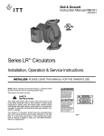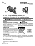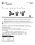
1
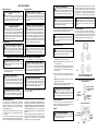
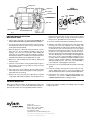
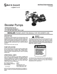
INSTRUCTION MANUAL
P81884G
UL
C
®
US
®
LISTED
P
L™ Booster Pumps
INSTALLER: PLEASE LEAVE THIS MANUAL FOR THE OWNER’S USE.
SAFETY
INSTRUCTIONS
This safety alert symbol will be used in this manual and on the
pump safety instructions decal to draw attention to safety
related instructions. When used, the safety alert symbol
means ATTENTION! BECOME ALERT! YOUR SAFETY IS
INVOLVED! FAILURE TO FOLLOW THE INSTRUCTIONS MAY
RESULT IN A SAFETY HAZARD.
Your Series PL ™ Booster Pump should have the warning/
caution label and nonsubmersible warning label (Fig. 1)
displayed on the pump conduit box. If this warning and caution is missing or illegible, contact your local Bell & Gossett
Representative for a replacement.
These pumps are designed to pump liquids compatible
with their iron or bronze body construction.
Maximum Working Pressure:
150 psi (10 bar)
Maximum Operating Temperature: 225°F (107°C)
Electrical Rating:
115V, 60 Hz, 1PH
230V, 60 Hz, 1PH
Do not exceed these values.
WARNING
BEFORE INSTALLING, USING
OR SERVICING THIS PRODUCT, READ THE INSTRUCTIONS. TO REDUCE RISK
OF ELECTRICAL SHOCK
SEE INSTRUCTIONS FOR
PROPER INSTALLATION.
CAUTION
FOR SUPPLY CONNECTIONS
USE WIRE SUITABLE FOR AT
LEAST 90°C. USE COPPER
CONDUCTORS ONLY.
EMPLOYER DES FILS
D’ALIMENTATION ADEQUATS
POUR 90°C. FOR INDOOR USE
ONLY. EMPLOYER UNIQUEMENT A L’INTERIEUR.
DESCRIPTION
The Series PL™ Booster Pump features permanently lubricated
bearings, non-overloading permanent split capacitor motor
with thermal protection and quiet operating construction.
WARNING
RISK OF ELECTRIC SHOCK;
THIS PUMP HAS NOT
BEEN INVESTIGATED FOR
USE IN SWIMMING POOL
AND MARINE AREAS.
-NONSUBMERSIBLE PUMP-
P86313
This pump is nonsubmersible, for indoor use only.
OPERATIONAL LIMITS
P48405
NOTE: Bell & Gossett recommends Bronze Booster Pumps
be used for pumping potable water.
FIG. 1
PUMP APPLICATION
The Series PL™ Booster Pump may be used for water circulating applications in hydronic and solar systems.
It has not been investigated, nor is it intended for use in swimming pool and marine areas.
SAFETY REQUIREMENTS
MECHANICAL SAFETY
ELECTRICAL SAFETY
WARNING: EXCESSIVE SYSTEM PRESSURE
HAZARD
The maximum working pressure of the pump is listed on
the nameplate – DO NOT EXCEED THIS PRESSURE.
Failure to follow these instructions could result in serious
personal injury, death and/or property damage.
WARNING: ELECTRICAL SHOCK HAZARD
Electrical connections are to be made by a qualified
electrician in accordance with all applicable codes, ordinances and good practices. Failure to follow these instructions could result in serious personal injury, death and/or
property damage.
WARNING: EXCESSIVE PRESSURE HAZARD –
VOLUMETRIC EXPANSION
The heating of water and other fluids causes volumetric
expansion. The associated forces may cause failure of system components and the release of high temperature fluids.
This can be prevented by installing properly sized and
located expansion tanks and pressure relief valves. Failure
to follow these instructions could result in serious personal
injury, death and/or property damage.
WARNING: ELECTRICAL GROUNDING HAZARD
Adequate electrical grounding is required for the safe
operation of B&G Pumps. The use of grounded metal conduit assures this requirement. If the means of connection to
the supply-connection box (wiring compartment) is other
than grounded metal conduit, ground the pump back to the
service by connecting a copper conductor at least the size
of the circuit conductors supplying the pump to the green
grounding screw provided within the wiring compartment.
Failure to follow these instructions could result in serious
personal injury, death and/or property damage.
THERMAL SAFETY
WARNING: EXTREME TEMPERATURE HAZARD
If the pump, motor, or piping are operating at extremely high or low temperature, guarding or insulation is
required. Failure to follow these instructions could result in
serious personal injury, death and/or property damage.
1. Close the valves on the suction and discharge sides of
the pump. If no valves have been installed, it may be necessary to drain the system.
WARNING: HOT WATER HAZARD
Before draining the system, allow water to cool to
100°F max. open the drain valve (take precautions against
water damage) and leave the drain valve open until servicing is complete. Failure to follow these instructions could
result in serious personal injury, death and/or property
damage.
WARNING: ELECTRICAL SHOCK HAZARD
Be certain the electrical power is not present at the
motor leads before continuing. Failure to follow these instructions could result in serious personal injury or death.
2. Loosen the conduit box cover screw and remove the cover.
WARNING: UNEXPECTED START-UP HAZARD
Single phase motors are equipped with automatic
reset overload protectors. The pump can restart without
warning. Disconnect and lockout power before servicing.
Failure to follow these instructions could result in serious
personal injury, death and/or property damage.
3. Disconnect the electrical supply lines to the pump.
WARNING: HIGH PRESSURE HAZARD
Pressure may be present in the pump body. This
pressure can be relieved by loosening the flange bolts and
shifting the pump assembly slightly to allow the pressurized water to escape. Failure to follow these instructions
could result in serious personal injury or death.
4. Remove the flange bolts and nuts and then remove the
pump from the piping.
PUMP INSTALLATION
Locate the pump so there is sufficient room for inspection,
maintenance and service. Bell & Gossett recommends the
installation of service valves on the suction and discharge of
all pumps to facilitate servicing or replacement of the pump
without draining the system.
Install suction and discharge flanges on the pipe ends. The
use of teflon tape sealer or a high quality thread sealant is
recommended.
Be sure to minimize any pipe-strain on the pump. Support the
suction and discharge piping by the use of pipe hangers near
the pump. Line up the vertical and horizontal piping so that
2
Do not start pump until the system has been filled and vented.
Air should be vented from the system by means of an air vent
located at a high point in the system, or by an alternate
method. The system must be completely vented prior to
pump operation. Do not run pumps dry. Pump operation without water circulation could result in pump and motor damage.
WARNING: HOT WATER HAZARD
Make sure that each flange gasket remains seated in
the flange groove during and after installation. Failure to follow these instructions could result in serious personal
injury, death and/or property damage.
WARNING: HOT WATER LEAKAGE HAZARD
Pressurize the body slowly while checking for leaks
at all joints with gaskets. Failure to follow these instructions
could result in serious personal injury and/or property
damage.
Apply torque in even increments to both flange bolts until a
value of 96-132 in-lbs. is reached. Both the suction and discharge flange bolts must be torqued in this manner.
WARNING: WATER LEAKAGE HAZARD
To prevent leakage, make certain that the flange
bolts have been adequately torqued. Failure to follow these
instructions could result in serious personal injury and/or
property damage.
MODE OF DISCHARGE
The Series PL ™ pump can be installed to discharge up or
down, horizontally, left or right, but the motor shaft must
remain in the horizontal position, the arrow on the body must
point in the direction of flow and the conduit box must be
positioned on the top of the motor housing (see figure 2).
WIRING INSTRUCTIONS
WARNING: RISK OF ELECTRIC SHOCK
Do not install this pump in swimming pool or marine
areas. Failure to follow these instructions could result in
serious personal injury, death and/or property damage.
REMOVAL OF THE PUMP FROM EXISTING SYSTEM FOR REPLACEMENT
WARNING: ELECTRICAL SHOCK HAZARD
Disconnect and lockout the power before servicing.
Failure to follow these instructions could result in serious
personal injury or death.
WARNING: HOT WATER HAZARD
When disassembling a gasketed joint, always use a
new gasket upon reassembly. NEVER RE-USE OLD GASKETS. Failure to follow these instructions could result in
serious personal injury, death and/or property damage.
WARNING: ELECTRICAL SHOCK HAZARD
Disconnect and lockout the power before making
electrical connections. Failure to follow these instructions
could result in serious personal injury or death.
A. Loosen the screw securing the conduit box cover (wiring
compartment), and remove the screw & cover.
B. Attach the appropriate size connector to the hole on the
side of the conduit box.
C. Using a minimum size 14 AWG copper electrical wire (refer
to your local code for wiring restrictions), wire the motor to
a single phase power source as listed on the pump nameplate. See Fig. 3.
D. Connect the ground wire to the inside of the conduit box
with one of the green screws provided inside the box. See
Fig. 4.
NOTE: Electrical supply and grounding wires must be suitable for at least 90°C (194°F).
Bell & Gossett flange gaskets must be installed between the
Series PL™ pump body flanges and the suction and discharge
pipe flanges. Use 7/16" diameter x 11/2" long capscrew and
matching nut to connect the pump to the flanges.
PUMP BODY MAY BE ROTATED AS SHOWN,
BUT CONDUIT BOX MUST REMAIN AT TOP.
TYPICAL WIRING INSTALLATION SCHEMATIC
FOR 1Ø POWER SOURCE
NOTE: Series PL™ Booster Pumps are thermally protected
and do not require external overload protection.
WARNING: ELECTRICAL SHOCK HAZARD
Be certain that all connections are secure and the
conduit box cover is closed before electrical power is connected. Failure to follow these instructions could result in
serious personal injury, death and/or property damage.
SYSTEM PREPARATION
the bolt-holes in the pump flanges match the bolt-holes in the
pipe flanges. (DO NOT ATTEMPT TO SPRING THE SUCTION
OR DISCHARGE LINES IN POSITION. THIS MAY RESULT IN
UNWANTED STRESS IN THE PUMP BODY, FLANGE CONNECTIONS AND PIPING.) The code for Pressure Piping
(ANSI B31.1) lists many types of supports available for various
applications.
FIG. 2
FUSIBLE DISCONNECT
OR CIRCUIT BREAKER
BY OTHERS
TO REMOTE
CONTROL
IF REQUIRED
PUMP MOTOR
THERMALLY
PROTECTED
FIG. 3
Prior to pump start up, closed heating and cooling systems
should be cleaned, drained and refilled with clean water.
System ph must be maintained between 7 and 9.
CONDUIT BOX WIRING DETAIL
STARTUP
CAUTION: SEAL DAMAGE HAZARD
Do not run pump dry, seal damage may occur. Failure
to follow these instructions could result in property damage
and/or moderate personal injury.
ALTERNATE
GROUND SCREW
FIG. 4
GREEN
GROUND
SCREW
LINE
LEADS
3
CONDUIT BOX
SHAFT SLEEVE
SEAL
COMPONENTS
PUMP BODY
BODY GASKET
COVER PLATE ASM
REAR
BEARING
IMPELLER ASM
W/THREADED HUB
SEAL
CUP
SEAL
SEAT
SEAL
SPRING
O-RING BACKUP
RING
SEAL ASM
FRONT BEARING
SHAFT/ROTOR ASM
CARBON
SEAL HEAD
SEAL
CAGE
Packaged together
as an assembly
HOUSING/STATOR ASM
FIG. 5
INSTRUCTIONS FOR REPAIRING
MECHANICAL SEAL
11. Follow steps 1 through 4 of section titled “REMOVAL OF
PUMP FROM EXISTING SYSTEM FOR REPLACEMENT.”
12. Loosen the four capscrews that hold the motor housing to
the pump body. Remove these screws and remove the
housing from the pump body.
13. Place the pump on a flat work surface and insert a screwdriver into one of the endplate ventilation slots until it
engages one of the rotor cooling fins. While holding the
rotor with the screwdriver, turn the impeller clockwise.
Note that the impeller is molded around a metal hub with a
left hand thread. Remove the impeller from the shaft.
14. Remove the seal assembly from the shaft by sliding it off
the shaft sleeve.
15. Clean the seal seat with a clean rag and inspect for grooving or cracks. If it shows no grooving or cracks, it may be
cleaned and reused.
Reposition the face plate on the motor housing. Gently
tap the face plate evenly around its diameter to drive it
into the recess provided in the motor housing.
18. Clean the shaft and sleeve before installing the new seal.
19. Slide the new carbon seal head onto the shaft sleeve until
it contacts the seal seat. Slide the new “O-Ring” and
back-up ring along the shaft sleeve until they fit inside the
counter bore in the seal head. Place the seal spring
between the back-up ring and the seal cage while positioning the seal cage flush with the end of the sleeve.
Place the small end of the spring against the back-up ring.
The three driving legs of the seal cage should engage the
three slots on the seal head. While holding the rotor
assembly with the screwdriver, thread the impeller onto the
shaft in a counter clockwise direction. Tighten the impeller
with light hand pressure. Take care to avoid bending a
rotor cooling fin or damaging the shaft sleeve.
10. Clean the recess in the pump body and install a new body
gasket.
16. If the seal seat is to be replaced, the face plate must be
removed from the motor housing. Remove it by gently prying it away from the housing.
11. Install the pump in the body and secure with four capscrews. Apply torque evenly in a criss cross pattern in 40
in-lb (4.52 N•m) increments to a torque of 80 in-lb (9.04 N•m).
17. Remove the seal seat and cup. Lubricate the cup with
soapy water and install new parts in the face plate recess.
12. Reinstall into the system using new flange gaskets. For
instructions, see sections “PUMP INSTALLATION” and
“WIRING INSTRUCTIONS” on pages 2 and 3.
PERIODIC INSPECTION
PERIODIC INSPECTION
Bell & Gossett Booster Pumps are designed to provide years
of trouble free service. It is recommended that periodic inspections be made to check for potential problems with the
pump. If any leakage or evidence of leakage is present repair
or replace the unit.
Xylem Inc.
8200 N. Austin Avenue
Morton Grove, Illinois 60053
Phone: (847) 966-3700
Fax: (847) 965-8379
www.xyleminc.com/brands/bellgossett
Bell & Gossett is a trademark of Xylem Inc. or one of its subsidiaries.
© 2012 Xylem Inc. P81884G April 2012