1
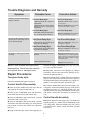
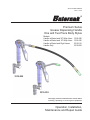
Service Bulletin SB3018 Rev. A 3/07 ® Premium Series Grease Dispensing Handle One and Two Piece Body Styles Models: Handle w/Swivel and 36" Whip Hose Handle w/Swivel and 18" Whip Hose Handle w/Swivel and Rigid Lance Handle Only 3310-020 3310-025 3310-010 3310-008 3310-025 3310-010 Thoroughly read and understand this manual before installing, operating or servicing this equipment. Operation, Installation, Maintenance and Repair Guide General Safety Thoroughly read and understand this manual before installing, operating or servicing this equipment. ! WARNING: Fluid emitted under high pressure from leaks and/or ruptured components can penetrate the skin and cause extremely serious bodily injury. If any fluid appears to penetrate the skin, apply emergency medical care at once. Do not treat the penetration as a simple cut. Tell your physician exactly what type of fluid was injected into your skin. ! WARNING: Do not place your hand or fingers over the dispensing nozzle and/or aim the nozzle at a person at any time. Personal injury may result. ! WARNING: Always use the following Pressure Relief Procedure whenever shutting off, cleaning, or in any way checking or servicing the control handle: Guide to Safety Comments: NOTE: Gives more explanation of a procedure, or a helpful hint. ! CAUTION: Alerts user to avoid or correct a condition which may or could cause damage and/or destroy the equipment. ! WARNING: Alerts user to avoid or correct conditions which could cause bodily injury. Because this Grease Control Handle can be incorporated into pressurized systems, the following safety precautions should be observed: (1) Disconnect air at the supply pump. (2) Point control handle outlet away from yourself and others. (3) Open dispensing valve until pressure is relieved. Check equipment regularly and repair or replace worn and damaged parts. Release pressures built up in the system before any service or repair is begun. See pressure relief procedure. ! WARNING: Never attempt to force lubricant into a fitting! If the lubricant is not flowing, stop dispensing immediately. Forcing lubricant into a fitting may cause excessive back pressure in the flexible extension. High back pressure could cause the extension and/or other components of the system to rupture, causing serious bodily injury. ! WARNING: High Pressure. Keep clear of nozzle. 7,500 psi maximum inlet pressure Never alter or modify any parts of this product; doing so may cause damage and/or personal injury. Never aim a dispensing valve at any person. Personal injury may result. Do not operate this product above 5000 PSI (345 BAR) grease supply pressure (limited by the whip hose rating). Always read and follow fluid manufacturers' recommendations regarding proper use of protective eyewear, clothing and respirators. ! NOTE: Observe all limitations which apply to BEFORE 3/07 - Two Piece Body Style selection of fluids which may be pumped by this product. AFTER 3/07 - One Piece Body Style 2 Table of Contents Trouble Diagnosis and Remedy...................... 4 Pump Repair................................................... 4 Parts List (two piece body style)...................... 6 Parts Diagrams (two piece body style)............ 6 Parts List (one piece body style)..................... 7 Parts Diagrams (two piece body style)............ 7 Waranty Statement.......................................... 8 Cover............................................................... 1 General Safety Information............................. 2 Product Description......................................... 3 Handle Installation........................................... 3 Operation . ...................................................... 3 Product Description and Specifications Pump grease through the grease feed line until all air is purged. The Premium Series High Pressure Grease Control Handle is designed for the following intended service: Adjust the control handle trigger as described below. (Two Piece Body Style Only) Single or multiple shot dispensing of automotive and industrial grease into standard ball coupling type grease fittings. The handle is ready for operation. Operation Flow dispensing of automotive and industrial grease onto open surfaces for lubrication purposes. The control handle is hand held and is operated by depressing the valve trigger. Grease is propelled by cycling the crank of a hand pump, or by the pumping pressure from an air-operated supply pump. Grease flow is proportional to the distance of movement of the trigger. Operation with any hand operated grease pump up to a working pressure of 5000 PSI (limited by the whip hose rating). Operation with pneumatic grease pumps with a ratio of 50:1 or less, and used with supply air pressure of 100 PSI or less (limited by the whip hose rating). A trigger stop adjustment and a valve plunger adjustment allow calibration of handle operation for best response and ease of operation. (Two Piece Body Style Only) The handle body is made of high strength steel. An attached whip hose allows flexible positioning of the hose end coupler for hard-to-reach grease application points. A z-swivel adapter allows freedom of motion of the handle relative to the high pressure supply hose. Lubricant Flow Adjustment! (Two Piece Body Style Only) Refer to product illustrations, page 7. Loosen the locking nut (15), then turn the adjusting screw (14) in or out to obtain the best trigger position. Lock the adjustment by tightening the nut (15). Installation Relieve system pressure. Use the pressure relief procedure on page 2. Trigger Adjustment (Two Piece Body Style Only) Attach the handle to the hose end thread, size 1/4 NPT(M). ! Refer to product illustrations, page 7. To improve angular operating position of the trigger, turn the adjusting screw (16) to modify the trigger home stop position. 3 Trouble Diagnosis and Remedy Symptom Grease continues to flow after the trigger is released. Probable Cause Two Piece Body Style Adjust Lubricant Flow, see procedure on page 3. Valve Ball (8) or seat (10) may be obstructed or worn, or spring may be weakened. Service and Replace the valve ball & seat, see procedures on page 4. Valve Ball (4) may be obstructed or worn, or spring may be weakened. Two Piece Body Style Valve plunger (6) or U-Packing (5) may be worn or damaged. One Piece Body Style Grease is leaking from swivel assembly. Two Piece Body Style Adjusting Screw (14) may be out of adjustment. One Piece Body Style Grease leaks around the valve plunger (6) two piece body style or (5) one piece body style. Corrective Action One Piece Body Style Service and Replace the valve ball or spring, see procedures on page 5. Two Piece Body Style Service and Replace u-packing, see procedures on page 5. One Piece Body Style Valve plunger (5) or V-Packing (6) may be worn or damaged. Service and Replace V-packing, see procedures on page 5. Swivel Packing may need to be tightened. Adjust collar/retaining nut. Tighten collar/retaining nut on swivel approximately 1/8 turn at a time and check for leaks again. Refer to SB5001 for High Pressure Z-Swivel. Swivel Packings have failed. Replace Swivel Assembly. NOTE: Clean all parts thoroughly when disassembling. Check the parts carefully and replace worn or damaged parts. Repair Procedures Two piece body style Refer to illustrations and parts list, page 6. Control Handle Disassembly Place the control handle in a bench vise, with the vise gripping the control handle body (1). Using a pair of adjustable open end wrenches, remove the whip hose (23) and coupler (24). Using an adjustable open end wrench, unscrew and remove the z-swivel (20). Using an adjustable open end wrench, unscrew and remove the whip hose fitting (22). Using a small pipe wrench, unscrew and remove the extension tube (21). Remove the trigger subassembly (12), (14), (15), (16), (17), (18), (19) and set aside. Using pliers, remove the valve plunger (6). Using a screwdriver, unscrew and remove the packing nut (4). Remove the packing seal (5). Using a strap wrench, unscrew and remove the hand grip (2). Then remove the following from the cavities in the body and hand grip: back-up washer (13), spring (11), gasket (7, two req'd), ball guide (9) and ball (10) If needed, disassemble parts from the trigger (12). Using pliers, remove the retaining ring (22). Then remove the adjusting spring (17), adjusting washer (18), and adjusting screw (16). Using a screwdriver and an open end wrench, remove the set screw (14) and hex nut (15). Control Handle Assembly Assemble parts from the trigger (12). First install the adjusting spring (17), washer (18), and adjusting screw (16). Using pliers, install the retaining ring (22). Using a screwdriver and wrench, install set screw (14) and hex nut (15). Using a mallet and pin, remove the trigger pin (3). 4 Place the control handle body (1) in a bench vise and clamp securely. Using an adjustable open end wrench, unscrew and remove the z-swivel (10). Install the following in the cavities of the body and hand grip: back-up washer (13), spring (11), gasket (7, two req'd), ball guide (9) and ball (10). Using a strap wrench, install the hand grip (2). Using an adjustable open end wrench, unscrew and remove the whip hose fitting (16). Using a small pipe wrench, unscrew and remove the extension tube (8 or 13). Install the packing seal (5). Using a large blade screwdriver, install and tighten the packing nut (4). Using pliers, install the valve plunger (6). Using a mallet and pin, remove the trigger pin (12). Remove the trigger (7) and set aside. Using pliers, remove the valve plunger (5). Using a screwdriver, unscrew and remove the packing nut (11). Remove the packing seal (6). Place the trigger subassembly (12), (14), (15), (16), (17), (18), (19) in position on the control handle. Using a small mallet and drive pin, install and center the trigger pin (3). Using a screwdriver, unscrew and remove the spring retainer (2). Then remove the spring (3) and the ball (4) from the body cavity. Using a pipe wrench, install the extension tube (21). Using an adjustable open end wrench, install and tighten the whip hose fitting (22). Control Handle Assembly Using an adjustable open end wrench, install and tighten the z-swivel (20). Place the control handle body (1) in a bench vise and clamp securely. Using a pair of open end wrenches, install and tighten the whip hose (23) and coupler (24). Install the ball (4) followed by the spring (3) into the cavity of the body. Using a screwdriver, install the the spring retainer (2) and tighten until snug. Valve and Trigger Adjustments Install the V-packing seal (6). Using a large blade screwdriver, install and tighten the packing screw (11). Install the valve plunger (5). Refer to Operation section, page 3 for valve and trigger adjustment procedures. U-packing Replacement Place the trigger (7) in position on the control handle. Using a small mallet and drive pin, install and center the trigger pin (12). Follow Control Handle Disassembly procedure steps, page 3, until u-packing is removed. Replace packing and follow appropriate sections of the Control Handle Assembly procedure, pages 3-4. Using a pipe wrench, install the extension tube (8 or 13). Using an adjustable open end wrench, install and tighten the whip hose fitting (16). Ball & Seat Replacement Using an adjustable open end wrench, install and tighten the z-swivel (10). Follow Control Handle Disassembly procedure steps, this page, until ball and seat are removed. Using a pair of open end wrenches, install and tighten the whip hose (14 or 15) and coupler (9). Replace ball and seat, then follow appropriate sections of the Control Handle Assembly procedure, this page. V-packing Replacement Repair Procedures Replace packing and follow appropriate sections of the Control Handle Assembly procedure, this page. Follow Control Handle Disassembly procedure steps, this page, until V-packing is removed. One piece body style Refer to illustrations and parts list, page 7. Ball Replacement Control Handle Disassembly Place the control handle in a bench vise, with the vise gripping the control handle body (1). Follow Control Handle Disassembly procedure steps, this page, until ball is removed. Using a pair of adjustable open end wrenches, Replace ball, then follow appropriate sections of the Control Handle Assembly procedure, this page. remove the whip hose (14 or 15) and coupler (9). 5 Grease Control Handle (2 Piece Body - Before 3/07) Parts List Handle Only Handle w/Swivel and Rigid Lance Handle w/Swivel and 36" Whip Hose Handle w/Swivel and 18" Whip Hose 3310-008 3310-010 3310-020 3310-025 Note: Repair Kit 811310 is available for standard repairs, consisting of one set of star (*) items. Item Part Number 3310020 3310008 3310010 3310025 1 808217 Body 1 1 1 1 2 3 807979 Hand Grip 1 1 1 1 819484 Trigger Pin 1 1 1 1 4* 808218 Packing Screw 1 1 1 1 5* 806473 U-Packing 1 1 1 1 6* 808215 Valve Plunger 1 1 1 1 7* 808056 Gasket 2 2 2 2 8* 805791 Ball, 5/16" Dia 1 1 1 1 Description 9 807609 Ball Guide 1 1 1 1 10* 807610 Ball Seat 1 1 1 1 11 806495 Valve Spring 1 1 1 1 12 808054 Trigger 1 1 1 1 13 807980 Back-up Washer 1 1 1 1 14 806497 Set Screw 1 1 1 1 15 806647 Hex Nut 1 1 1 1 16 807612 Adjusting Screw 1 1 1 1 17 807939 Adjusting Screw 1 1 1 1 18 807650 Adjusting Screw 1 1 1 1 19 808065 Retaining Ring 1 1 1 1 20 5310-018 Z-Swivel 1 1 1 21 806195 Extension Tube, Short 1 806197 Extension Tube, Long 22 830045 Fitting, Whip Hose 1 23 8390-003 Whip Hose, 36 Inch 1 8390-002 Whip Hose, 18 Inch 5310-020 Hydraulic Coupler 24* 15 14 3 21 6 4 5 1 16 17 18 19 7 8 10 7 9 12 11 2 13 1 1 1 Detail Section View 1 1 1 1 1 1 20 15 14 21 22 Side View 3 23 16 17 18 19 1 2 24 12 20 6 Grease Control Handle (1 Piece Body - After 3/07) Parts List Handle Only Handle w/Swivel and Rigid Lance Handle w/Swivel and 36" Whip Hose Handle w/Swivel and 18" Whip Hose 3310-008 3310-010 3310-020 3310-025 3310008 3310010 BODY/HP. CONTROL HANDLE 1 1 1 1 832217 RETAINER/SPRING 1 1 1 1 3 808216 SPRING 1 1 1 1 4 805791 BALL - 5/16 1 1 1 1 5 832218 PLUNGER/HP. CONT. HDLE 1 1 1 1 6 806473 V-PACKING 1 1 1 1 7 832219 TRIGGER/HP. CONT. HDLE 1 1 1 1 8 806197 TUBE, LONG 1 1 9 5310-020 SUPER GRIP HYD COUPLER 1 1 1 1 10 827642 SWIVEL-Z/H.P. 1 1 1 11 808218 SCREW/PACKING 1 1 1 1 12 819484 PIN, DRIVE 1 1 1 1 13 806195 TUBE, SHORT 1 1 14 832225 HOSE, WHIP, HP, 36" 1 15 832226 HOSE, WHIP, HP, 18" 16 830045 FITTING, ADAPTER ITEM PART DESCRIPTION 1 832216 2 3310- 3310020 025 1 1 7 1 Balcrank Lubrication Equipment Warranty Statement All Balcrank equipment sold by authorized Balcrank distributors is warranted to their original customer to be free from defects in materials and workmanship for a period of one year from the date of sale to that customer. Selected Balcrank equipment carries warranty terms for a more extended period as defined in the Balcrank Lubrication Equipment & Accessories User Price List, wherein a “lifetime” warranty represents a warranty period of thirty years. Within the initial one-year warranty period, Balcrank will repair or replace all Balcrank equipment determined by Balcrank to have defective materials or workmanship. For equipment carrying more extended warranties, Balcrank will repair or replace the product including parts and labor during the first full year and will provide parts only for the remainder of the warranty period. This warranty applies only to equipment installed and operated according to applicable Balcrank Service Bulletins and Installation Instructions. Any equipment claimed to be defective must be returned, freight prepaid, to an Authorized Balcrank Service Center (ASC). Upon receiving candidate warranty equipment from a customer, ASC will: 1) diagnose to determine the warrantable condition of the equipment, 2) submit, prior to repair or replacement, a request to Balcrank for warranty authorization, then 3) in cooperation with Balcrank, proceed with repair locally or forward the equipment to Balcrank and obtain replacement. If the part(s) or equipment items are found defective upon inspection by Balcrank, they will be repaired or replaced, and then will be returned to the ASC. If Balcrank finds the claimed part(s) or equipment not to be defective, the ASC will receive written authorization from the original customer, and then repair them for a reasonable charge to the customer, which will include all applicable parts, labor, and return transportation costs. Optionally, the customer may submit certain eligible products directly to Balcrank for warranty return by using Balcrank Lubrication Equipment Direct Service Warranty Procedure. Eligible products are defined in the Balcrank Lubrication Equipment & Accessories User Price List. Refer to the Balcrank web site www. balcrank.com for a copy. Any equipment returned to Balcrank must have the Warranty Service Claim number (WSC#) clearly marked on the outside of the carton. Balcrank’s sole responsibility is for defects in material and workmanship, and Buyer’s sole and exclusive remedy hereunder, shall be limited to repair or replacement of the defective part or equipment. This warranty does not cover, nor shall Balcrank be liable for repair or replacement of parts or equipment resulting from general wear and tear through use, or damage or failure caused by improper installation, abuse, misapplication, abrasion, corrosion, insufficient or improper maintenance, negligence, accident, alteration, or substitution of non-Balcrank parts. Furthermore, the Warranty for Lubrication Equipment and Accessories does not cover the following specific conditions: • • • • • • • • Failure or damage to equipment caused by dirt or debris in compressed air lines and fluid lines. This includes, but is not limited to, clogged inlet filters, strainers, or regulators; fluid meters; control handles; fluid tips; and valves. Failure of normal wear parts including but not limited to: o-rings, packings, seals and valves unless originally improperly installed by the factory. Products placed in applications for which their use was not intended. Examples include but are not limited to Lubricant pump being used to pump solvents, or placing equipment intended strictly for indoor use outdoors Damage to equipment resulting from operation above and beyond Balcrank’s recommendations. Leaks at air and fluid fittings and connections. Damage caused by thermal expansion whenever adequate pressure relief was not included in the system. Loose suction tubes on pumps. Incorrect hose reel spring tension, requiring adjustment. THERE ARE NO OTHER WARRANTIES, EXPRESSED OR IMPLIED, INCLUDING WARRANTIES OF MERCHANTABILITY OR FITNESS FOR A PARTICULAR PURPOSE. IN NO EVENT SHALL BALCRANK BE LIABLE FOR ANY SPECIAL, CONSEQUENTIAL, OR OTHER DAMAGES OF SIMILAR NATURE, INCLUDING BUT NOT LIMITED TO LOST PROFITS, LOST PRODUCTION, PROPERTY DAMAGE, PERSONAL INJURY, WHETHER SUFFERED BY BUYER OR ANY THIRD PARTY, IRRESPECTIVE OF WHETHER CLAIMS OR ACTIONS, LEGAL OR EQUITABLE, FOR SUCH DAMAGES ARE BASED UPON CONTRACTS, WARRANTY, NEGLIGENCE, STRICT LIABILITY, OR OTHERWISE. ANY CLAIM OR ACTION FOR BREACH OF WARRANTY MUST BE BROUGHT WITHIN TWO (2) YEARS FROM THE DATE OF SALE TO THE ORIGINAL CUSTOMER. Balcrank® Products, Inc. 115 Reems Creek Road Weaverville, NC 28787 800-747-5300 800-763-0840 Fax www.balcrank.com Service Bulletin SB3018 Rev. A 3/07 830111 Distributed by: Revision Log: Rev. A - release of new 1 piece handle body