1
Allwinner Technology CO., Ltd.
Configuration System
&
GPIO Management
V1.01
April 22, 2011
Configuration System and GPIO Management V1.01
Copyright © 2011 Allwinner Technology. All Rights Reserved.
April 22, 2011
Allwinner Technology CO., Ltd.
Revision History
Version
Date
Section/ Page
Changes Compared to Previous Issue
V1.00
2011.1.22
Initial version
V1.01
2011.4.22
Add configuration system workflow
Configuration System and GPIO Management V1.01
Copyright © 2011 Allwinner Technology. All Rights Reserved.
April 22, 2011
1
Allwinner Technology CO., Ltd.
Table of Contents
Revision History ............................................................................................................................... 1
Table of Contents .............................................................................................................................. 2
1.
Introduction ............................................................................................................................... 4
2.
Term Definition ......................................................................................................................... 5
3.
4.
5.
2.1.
Configuration Script ...................................................................................................... 5
2.2.
Main Key....................................................................................................................... 5
2.3.
Subkey........................................................................................................................... 5
2.4.
Subkey Value................................................................................................................. 6
2.5.
GPIO Description .......................................................................................................... 6
2.6.
Configuration Script Modification ................................................................................ 8
Configuration System Workflow and Application................................................................... 10
3.1.
Generate Configuration Data in PC ............................................................................ 10
3.2.
Data Transfer in System Boot ..................................................................................... 11
3.3.
Data Transfer in Configuration System Calling .......................................................... 11
3.4.
Configuration System Application .............................................................................. 13
3.4.1.
Application Overview ..................................................................................... 13
3.4.2.
Different Hardware Modules........................................................................... 13
3.4.3.
Difference Parameters for the Same Modules ................................................. 14
3.4.4.
Customized Parameters ................................................................................... 15
How to Use Configuration Script ............................................................................................ 17
4.1.
Fetch Configuration Parameters .................................................................................. 17
4.2.
Fetch the Number of Subkeys ..................................................................................... 19
4.3.
Fetch the Number of Main Keys ................................................................................. 20
4.4.
Get the Number of GPIO in Main Keys ...................................................................... 21
4.5.
Fetch the GPIO Data in Main Keys ............................................................................ 22
GPIO Management .................................................................................................................. 24
Configuration System and GPIO Management V1.01
Copyright © 2011 Allwinner Technology. All Rights Reserved.
April 22, 2011
2
Allwinner Technology CO., Ltd.
5.1.
6.
Request GPIO ............................................................................................................. 24
5.1.1.
Request GPIO Through Main Keys ................................................................ 25
5.1.2.
Request GPIO Through Main Keys and Subkeys ........................................... 26
5.1.3.
Request GPIO Through Customization ........................................................... 27
5.2.
Release GPIO .............................................................................................................. 28
5.3.
Fetch all the GPIOs Configuration of a Handle .......................................................... 28
5.4.
Fetch One GPIO Configuration of a Handle ............................................................... 32
5.5.
Set One GPIO Configuration of the Handle................................................................ 33
5.6.
Set One GPIO IO Status of the Handle ....................................................................... 36
5.7.
Set One GPIO Build-in Resistor Status of the Handle ................................................ 37
5.8.
Set One GPIO Driver Strength of the Handle ............................................................. 38
5.9.
Read One GPIO Level of the Handle .......................................................................... 40
5.10.
Set One GPIO Port Level of the Handle ................................................................. 43
5.11.
The Handle in GPIO Management .............................................................................. 46
5.11.1.
What Handles are Used for?............................................................................ 46
5.11.2.
Avoid Conflict of GPIO Access among Modules............................................ 46
5.11.3.
Avoid Conflict between Modules and IO ........................................................ 48
5.11.4.
Avoid Conflict between IO Input and IO Output ............................................ 48
FAQ ......................................................................................................... 错误!未定义书签。
Configuration System and GPIO Management V1.01
Copyright © 2011 Allwinner Technology. All Rights Reserved.
April 22, 2011
3
Allwinner Technology CO., Ltd.
1. Introduction
This user manual introduces some conceptions and function interfaces of configuration system and
GPIO management. It also provides lots of examples so that users can solve related problems
accordingly.
The targeted readers of this manual cover all those people who have used or interested in
configuration system and GPIO management.
Configuration System and GPIO Management V1.01
Copyright © 2011 Allwinner Technology. All Rights Reserved.
April 22, 2011
4
Allwinner Technology CO., Ltd.
2. Term Definition
This section briefs some basic terms in configuration system and GPIO management.
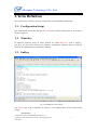
2.1. Configuration Script
The configuration system takes the form of a Script on PC, and is suffixed with ini. Its content is
shown in Figure 2-1.
2.2. Main Key
In Figure2-2, character strings in square brackets are called Main Keys, such as [target],
[twi_para], etc. They can be as long as 32 characters, excluding the end mark. Moreover, main key
names in one configuration script should be different.
2.3. Subkey
Fig 2-3Configuration Script Demo
The subkeys refer to the components of main keys. For example, there are four entries below
[target]:
Debugenable
=1
Configuration System and GPIO Management V1.01
Copyright © 2011 Allwinner Technology. All Rights Reserved.
2011-04-22
5
Allwinner Technology CO., Ltd.
Storage_mode
=0
Boot_clock
= 406
Core_vol
= 1400
Character strings at the left of “=” are subkeys of the main key Target. The subkey can be as long
as 32 characters, excluding the end mark. The subkeys names in one main key should be different,
but subkey names in different main keys in a script can be identical.
2.4. Subkey Value
The subkey value takes three forms:
1) The subkey values in Fig 2-4 are integers, such as 1, 0, 406, etc. It can be in hexadecimal
system, but not expressions. For example, in twi_para, the twi_port subkey value is 0;
2) The subkey value can also be a GPIO description. For example, twi_scl value is:
twi_scl = port: PB0<2><default><default><default>
3) The subkey value can also be a character string following “string”, which cannot exceed 128
bytes. For example, the string_test value is:
String_test = string:1234567890
2.5. GPIO Description
1) Port Group: (such as PortA, PortB)
Each port group includes several GPIO. The port group numbers vary in different IC.
2) Serial Number:
The serial number refers to the sequence of a GPIO in a port group. For example, the 22th pin of
PortA, 22 is its serial number. Since the serial number of each group begins with 0, PB3 refers to
the third pin of PortB, but it’s actually in the fourth sequence. This 0 rule is of little significance in
practice, you just need to refer to the IC pins given on circuit diagram.
3) Function
The function indicates which module uses the GPIO. As for that, reference can be made to related
Specification.
For example, in the main key twi_para (twi_scl = port: PB0<2><default><default> <default>),
its two subkeys are used as Function 2.
4) Build-in Resistor
The build-in resistor, also called Pull-up Resistor or Pull-down Resistor, is an attribute of pins.
Configuration System and GPIO Management V1.01
Copyright © 2011 Allwinner Technology. All Rights Reserved.
2011-04-22
6
Allwinner Technology CO., Ltd.
Generally, the pull-up resistor is used by default.
In GPIO description, the build-in resistor description is in the second “< >”, behind the Function
description:
0—High resistance;
1—Pull-up;
2—Pull-down;
Default—default state, Pull-up;
Except 0/1/2/Default, other options are invalid.
For example, to twi_scl (twi_scl = port: PB0<2><default><default> <default>), the first
“default” refers to the state of internal resistor, i.e. Pull-up.
5) Driver Strength
The driver strength defines the ability of a GPIO: the larger the driver strength, the sharper the IO
level changes. Generally, the default value is used.
The driver strength is described in the third “< >”, just following the build-in resistor description:
0— the drive strength level is 0;
1— the drive strength level is 1;
2— the drive strength level is 2;
3— the drive strength level is 3;
Except 0/1/2/3, other options are invalid.
For example, in twi_para, the SCL and SDA driver strength is “default”, that is Level 1.
6) Output Level
The last item in GPIO description is the GPIO output level.
When a GPIO is used as an IO, i.e. Function1, the IO output level status can be set here: 0—low
level, 1—high level. If a GPIO is not used as an IO, this item in description is pointless.
In conclusion, the complete format of GPIO description is:
Port: Port Group + Serial Number<Function><Build-in Resistor><Driver Strength><Output
Level>
And this form has some variants.
Here takes twi_para as an example:
Configuration System and GPIO Management V1.01
Copyright © 2011 Allwinner Technology. All Rights Reserved.
2011-04-22
7
Allwinner Technology CO., Ltd.
twi_scl = port:PB0<2><default><default><default>
(1)
twi_scl = port:PB0<2><default><default>
(2)
twi_scl = port:PB0<2><default>
(3)
twi_scl = port:PB0<2>
(4)
These four have the same meaning: the 0 pin of Port B, Function2, default build-in resistor (1,
pull-up), default driver strength (since it’s used as TWI function, a non-output state, the output
level is invalid).
The (1) is a complete GPIO description format;
The (2) leaves out the output level information, which can be applied to situations where the
Function is non-output; if the GPIO is set to output, the IO level will remain unchanged;
The (3) leaves out the output level and driver strength information, in which case the driver
strength is Level 1, and the output level remains unchanged;
The (4) leaves out the output level, driver strength, and build-in resistor information, in which case
the resistor is pulled up, and driver strength is Level 1, and the output level remains unchanged.
2.6. Configuration Script Modification
Modification can be made to configuration script easily via text compilation tools. These
modifications can be:
1) modify the main key name, such as modify [target] to [targetX];
2) modify the subkey name, such as modify the boot_clock of Target to boot0_clock;
3) modify the subkey value, such as change the boot_clock value from 406 to 384, change
the twi_sda value to twi_sda = port:pb0<2><2><2><1>;
4) remove a main key:
If a main key has been removed, all its subkeys should be deleted as well. For example,
after [target] is removed, its subkeys debugenable/storage_mode/ boot_clock/core_vol
and their values should be removed.
5) remove a subkey:
If a subkey is removed, its name and value should be removed.
6) add a main key:
A main key can be empty without any subkey. For example, there is a main key [empty],
and then another main key [target] locates directly below it, then the [empty] is an empty
Configuration System and GPIO Management V1.01
Copyright © 2011 Allwinner Technology. All Rights Reserved.
2011-04-22
8
Allwinner Technology CO., Ltd.
main key.
7) add a subkey
To add a subkey, please confirm which main key it belongs to. Usually, a subkey doesn’t
stand-alone, and belongs to the nearest main key above. Besides, the subkey value should
be finalized in the mean time. If the value cannot be confirmed, set it to 0.
8) Adjust the subkey position
It’s pointless adjusting a subkey position within the main key, but relocating it to another
main key endows it with a different meaning.
Configuration System and GPIO Management V1.01
Copyright © 2011 Allwinner Technology. All Rights Reserved.
2011-04-22
9
Allwinner Technology CO., Ltd.
3. Configuration
Application
System
Workflow
and
This section will detail how the configuration script goes from PC to devices, and how data is
delivered in system when the configuration script is used.
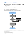
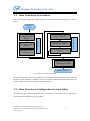
3.1. Generate Configuration Data in PC
Following figure has illustrated how a data file in PC is made accessible to devices.
Configuration program
(assist in parameter
configuration)
Generate original
configuration script
Manual
modification? Y/N
Y
Modify configuration
scripts manually
N
Transform configuration
scripts to data, and
embed it to boot1.bin.
Packing System
PC configuration interface
finishes.
Fig 3-1 Device-End Configuration File Generation
It can be seen that after the configuration script is generated, it can be embedded into boot just by
simple packing and loading.
Configuration System and GPIO Management V1.01
Copyright © 2011 Allwinner Technology. All Rights Reserved.
April 22, 2011
10
Allwinner Technology CO., Ltd.
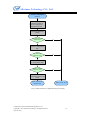
3.2. Data Transfer in System Boot
After system startup, data will be read from boot to OS-defined location for OS access, as shown
below.
System
boot
Read the
configuration data
address
Move data to the system
reserve data area
Boot finishes. Jump
to the OS.
Initialize the configuration
management module
Operation Phase
BOOT Phase
Move data in
boot1.bin to defined
address
Provide the user operation
service
Exit the configuration
management module
System shutdown
Fig 3-2 Data Transfer in System Boot
During the Boot phase, data is read from boot1.bin and then delivered to the OS. After acquiring
the data, OS will initialize it, and then wait for user operations. When the system is shutdown, OS
needs to call the exit function of configuration management.
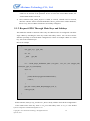
3.3. Data Transfer in Configuration System Calling
The following figure has presented how data is transferred to the system and how the system
reacts when the configuration system is called.
Configuration System and GPIO Management V1.01
Copyright © 2011 Allwinner Technology. All Rights Reserved.
April 22, 2011
11
Allwinner Technology CO., Ltd.
Call the configuration
function
The OS acquires
parameters and deliver
them to configuration
management module
Check the parameters
validity
The parameters are
valid?(Y/N)
N
Y
Match the main key
name in configuration
data
Y
The main key
matches?(Y/N)
N
Match the subkey name
in configuration data
Y
Subkey name
matches?(Y/N)
N
Put the matched
configuration data to user
buffer
Data acquisition
finishes, Exit
Errors occur, Exit
Fig 3-3 Data Transfer in Configuration System Calling
Configuration System and GPIO Management V1.01
Copyright © 2011 Allwinner Technology. All Rights Reserved.
April 22, 2011
12
Allwinner Technology CO., Ltd.
3.4. Configuration System Application
3.4.1. Application Overview
The discrepancies among different programs can be classified into four categories:
1) Different hardware modules, such as NAND Flash, RTC, etc;
2) Different parameters for the same hardware modules, such as GPIO, card detect pin, SPI
pin, etc; and different work frequency, such as DRAM frequency, CPU frequency, etc;
3) Different routing
4) Other differences
If programs have adopted different hardware modules or different parameters for the same module,
the system may need recompilation, while differences in routing or other aspects needn’t.
3.4.2. Different Hardware Modules
To handle the hardware module difference, some code can be made self-adaptive, for example, if
the NAND model can be automatically scanned, the flash driver needn’t be reconfigured. But for
those modules whose hardware models cannot be scanned, they should be reconfigured.
Take the RTC as an example:
The RTC needs configuration system for management in that some programs use internal RTC
modules while others use external RTC. Detailed method is that first, put all supported RTC
models to RTC driver, and provide corresponding codes as well; second, write configuration items
to configuration system, and specify the relationship between configuration and RTC, for example:
(supposing the internal RTC driver, external RTC XXXX driver and external RTC YYYY driver
have been provided)
Configuration 0 is related to internal RTC;
Configuration 1 is related to external RTC, model: XXXX;
Configuration 2 is related to external RTC, model: YYYY;
To realize that, a main key should be created in the configuration script, and then name the key
(the name is recommended to be in line with its function);
[rtc_select]
And then create the subkeys below the main key;
rtc_pattern = 0
Configuration System and GPIO Management V1.01
Copyright © 2011 Allwinner Technology. All Rights Reserved.
April 22, 2011
13
Allwinner Technology CO., Ltd.
This indicates that internal RTC is used, and the model is 0.
If the subkey is:
rtc_pattern = 2
This indicates that external RTC is used, and the model is YYYY.
In conclusion, in order to use a supported RTC, you just modify the RTC subkey value in
configuration script. (All supported RTC models and configuration values are clarified in Spec or
related materials.)
In fact, following function is called in RTC driver to process the configuration:
{
int rtc_pattern;
int ret;
ret = OSAL_Script_FetchParser_Data(“rtc_select”, “rtc_pattern”, &rtc_pattern, 1);
if(ret >= 0)
return rtc_pattern;
else
return ret;
}
By calling this function, the RTC driver can fetch the RTC model set by users. As long as the user
configuration is identical with the program, the RTC can work normally. This method enables
RTC model modification without having to regenerating or replacing the RTC driver.
3.4.3. Difference Parameters for the Same Modules
As for this point, here takes the Card Detect as an example:
Generally, the GPIO is used as the Card Detect Pin: the card is regarded as inserted when it’s low
level, and not inserted when it’s high level. Since the card detect pins vary in different programs,
instead of altering card pin detect modules, configuration items can be used to report which pin is
used, see below:
Configuration System and GPIO Management V1.01
Copyright © 2011 Allwinner Technology. All Rights Reserved.
April 22, 2011
14
Allwinner Technology CO., Ltd.
[sddet_para]
detect_pin = port: PI4<0><1><1>
The main key sddet_para shows that this is a parameter related to card detect; The subkey
detect_pin indicates which is the detect pin: 4th pin of Port I, input, build-in resistor pulled-up,
driver strength level 1;
With these configuration items, you can only change the detect pin simply by modifying the
configuration here. For example, to change the 14th pin of port A as the detect pin:
[sddet_para]
detect_pin = port: PA14<0><1><1>
3.4.4. Customized Parameters
This section introduces how to use configuration customization to meet different requirements.
For example, if you want to use configuration for the FM module management, which happens
rarely though, steps below can be followed:
First, create following configuration items:
[fm_para]
fm_pattern = 0
According to the relationship between fm_type and FM models (for example, 0 is RDA5820,1 is
TEA5767,and 2 is QN8006),FM adopted here is RDA5820.
In the FM driver, following code is used to fetch the used FM pattern-- RDA5820, so that the right
code can be found later for FM driver to work normally.
Configuration System and GPIO Management V1.01
Copyright © 2011 Allwinner Technology. All Rights Reserved.
April 22, 2011
15
Allwinner Technology CO., Ltd.
{
int fm_pattern;
int ret;
ret = OSAL_Script_FetchParser_Data(“fm_para”, “fm_pattern”, &fm_pattern, 1);
if(ret >= 0)
return fm_pattern;
else
return ret;
}
Configuration System and GPIO Management V1.01
Copyright © 2011 Allwinner Technology. All Rights Reserved.
April 22, 2011
16
Allwinner Technology CO., Ltd.
4. How to Use Configuration Script
This section will elaborate on how to use the configuration script.
In the system, following functions are provided to fetch the configuration information.
4.1. Fetch Configuration Parameters
Function: int OSAL_Script_FetchParser_Data(char *main_name, char *sub_name, int
value[], int count);
Parameters:main_name
main key name in configuration script, in character string
sub_name
subkey name in configuration script, in character string
value
data pointer, used to store fetched data
count
the maximum word number of the transferred dataspace
Returned value: if succeed, return 0;
If fail, return -1
This function is powerful enough to fetch any value in the configuration script. For example, if
you want to get the subkey value of boot_clcok in main key Target:
{
int value;
int ret;
ret = OSAL_Script_FetchParser_Data(“target”, “boot_clock”, &value, 1);
if(ret < 0)
printf(“fetch script data fail\n”);
else
printf(“fetch script data ok, value = %d\n”, value);
return ret;
}
The value fetched will be put to integer variable value, and usually the value is 406.
Configuration System and GPIO Management V1.01
Copyright © 2011 Allwinner Technology. All Rights Reserved.
April 22, 2011
17
Allwinner Technology CO., Ltd.
{
If you want to get the GPIO data, such as the twi_scl in twi_para, you can use:
user_gpio_set_t gpio_info[1];
int ret;
ret
=
OSAL_Script_FetchParser_Data(“twi_para”,
“twi_scl”,
gpio_info,
sizeof(user_gpio_set_t)/sizeof(int));
if(ret < 0)
printf(“fetch script gpio information fail\n”);
else
printf(“fetch script gpio information ok \n”);
return ret;
}
This function will put the fetched GPIO information into gpio_info, which can then be used to call
functions provided by GPIO management module.
Besides, you can use the script function to get a character string. For example, with regards to
following main key and subkey,
[string_test]
string_demo = string:abcdefghijklmn
the subkey string_demo value can be accessed by calling following function, and the value saved
in string_info will be abcdefghijklmn in normal circumstances.
Configuration System and GPIO Management V1.01
Copyright © 2011 Allwinner Technology. All Rights Reserved.
April 22, 2011
18
Allwinner Technology CO., Ltd.
{
char string_info[128];
int ret;
memset(string_info, 0, 128);
ret = OSAL_Script_FetchParser_Data(“string_test”, “string_demo”, string_info,
128/sizeof(int));
if(ret < 0)
printf(“fetch script string information fail\n”);
else
printf(“fetch script string information ok \n”);
return ret;
}
4.2. Fetch the Number of Subkeys
Function:int OSAL_Script_FetchSubKey_Count(char *main_name);
Parameters:main_name the main key name in configuration script, in character string
This function
definitely
of fetching
thenumber
numberofofsubkeys
subkeys in a main key, nevertheless,
Returned
value:is capable
if succeed,
return the
it’s mainly used for check.
If fail, return -1
Configuration System and GPIO Management V1.01
Copyright © 2011 Allwinner Technology. All Rights Reserved.
April 22, 2011
19
Allwinner Technology CO., Ltd.
{
int sub_key_count;
sub_key_count = OSAL_Script_FetchSubKey_Count (“target”);
if(sub_key_count < 0)
printf(“fetch script sub key count fail\n”);
else
printf(“fetch script sub key count ok ,
sub_key_count =
%d\n”,
sub_key_count);
return sub_key_count;
}
By calling the function, you will get the number of all subkeys in target: 4
4.3. Fetch the Number of Main Keys
Function:int OSAL_Script_FetchMainKey_Count(void);
Parameters:No
Returned value: if succeed, return the number of main keys
If fail, return -1
Just as OSAL_Script_FetchSubKey_Count, this function is mainly used to check.
This function is capable of fetching the number of all the main keys, however, it’s primarily used
for check as well.
Configuration System and GPIO Management V1.01
Copyright © 2011 Allwinner Technology. All Rights Reserved.
April 22, 2011
20
Allwinner Technology CO., Ltd.
{
int main_key_count;
main_key_count = OSAL_Script_FetchMainKey_Count();
if(main_key_count < 0)
printf(“fetch script sub key count fail\n”);
else
printf(“fetch script main key count ok , main_key_count = %d\n”,
main_key_count);
return main_key_count;
}
By calling this function, you can get the number of main keys in configuration script.
4.4. Get the Number of GPIO in Main Keys
Function:int OSAL_Script_FetchMainKey_GPIO_Count(char *main_name);
Parameters:main_name the main key name in configuration script, in character string
Returned value: if succeed, return the number of GPIO subkey;
if fail, return -1.
By calling this function, the number of GPIO subkeys can be available.
For example, that the twi_para has 2 GPIO subkeys can be known through:
Configuration System and GPIO Management V1.01
Copyright © 2011 Allwinner Technology. All Rights Reserved.
April 22, 2011
21
Allwinner Technology CO., Ltd.
{
int gpio_key_count;
gpio_key_count = OSAL_Script_FetchMainKey_GPIO_Count (“twi_para”);
if(gpio_key_count < 0)
printf(“fetch script sub key count fail\n”);
else
printf(“fetch
script
gpio
key
count
ok
,
gpio_key_count
=
%d\n”,
gpio_key_count);
return gpio_key_count;
}
If the parameter twi_para above is changed to target, 0 is returned; if it’s changed to nand_para,
23 is returned.
4.5. Fetch the GPIO Data in Main Keys
Function OSAL_Script_FetchMainKey_GPIO_Data is used to fetch the GPIO data in main keys.
Function : int OSAL_Script_FetchMainKey_GPIO_Data(char *main_name, void
*gpio_cfg, int gpio_count);
Parameters:main_name
main key name in configuration script, in character string
gpio_cfg
used to store GPIO information, a member of user_gpio_set_t
gpio_count
the number of structs transferred in by users
Returned Value: if succeed, return 0;
if fail, return -1.
By calling this function, you can get the number of GPIO subkeys fitting the main key name.
Configuration System and GPIO Management V1.01
Copyright © 2011 Allwinner Technology. All Rights Reserved.
April 22, 2011
22
Allwinner Technology CO., Ltd.
{
user_gpio_set_t gpio_info[2];
int ret;
ret = OSAL_Script_FetchMainKey_GPIO_Data(“twi_para”,gpio_info, 2);
if(ret < 0)
printf(“fetch script gpio information fail\n”);
else
printf(“fetch script gpio information ok \n”);
return ret;
}
By calling this function, you can get the GPIO subkey data in twi_para.
Configuration System and GPIO Management V1.01
Copyright © 2011 Allwinner Technology. All Rights Reserved.
April 22, 2011
23
Allwinner Technology CO., Ltd.
5. GPIO Management
The GPIO configuration is used to define the GPIO usage in the script, and it can be realized by
heaps of functions provided by the system.
5.1. Request GPIO
Following function is used to request the GPIO handle and configure the GPIO attribute. It should
work with configuration script or a customized GPIO.
Function : __hdle
OSAL_GPIO_Request
(user_gpio_set_t
*gpio_list,
__u32
group_count_max);
Parameters:gpio_list
data address, used to save the GPIO attribute originating
from configuration script or user customization
group_count_max
Returned Value:
the maximum number of GPIO data structs that can be saved
if succeed, return a non-NULL pointer;
if fail, return a NULL pointer
The data struct of user_gpio_set_t is shown below:
typedef struct
{
char gpio_name[32];
//the GPIO name
int port;
//GPIO Port
int port_num;
//GPIO Port number
int mul_sel;
//GPIO function
int pull;
//GPIO build-in resistor status
int drv_level;
//GPIO driver strength
int data;
//GPIO level
}
user_gpio_set_t;
After this function is called, all configurations become valid.
Configuration System and GPIO Management V1.01
Copyright © 2011 Allwinner Technology. All Rights Reserved.
2011-04-22
24
Allwinner Technology CO., Ltd.
As for how to configure GPIO, following THREE methods are provided.
5.1.1. Request GPIO Through Main Keys
The GPIO information can be fetched by searching main keys in configuration script if GPIO
information comes from the configuration script. GPIO in main keys can be one or more, but if
there is no GPIO, the fetch will fail.
Here is an example:
{
user_gpio_set_t gpio_info[2];
int ret;
__hdle
gpio_hd;
ret = OSAL_Script_FetchMainKey_GPIO_Data(“twi_para”, (void *)gpio_info, 2);
if(ret < 0)
{
printf(“fetch script gpio information fail\n”);
return -1;
}
gpio_hd = OSAL_GPIO_Request(gpio_info, 2);
return gpio_hd;
}
In the example above,
1) OSAL_Script_FetchMainKey_GPIO_Data is called to fetch the GPIO configuration, and
then parameter“twi_para”is used to search all GPIO subkeys fitting the main key name
twi_para in configuration script, and the searched GPIO configuration parameters are put
to gpio_info. All attributes should be stored accordingly: gpio_name stores the subkey
names in configuration script, for example, GPIO name of twi_scl is twi_scl, and GPIO
name of twi_sda is twi_sda.
The third parameter “2” means to fetch two GPIO only. If the number of GPIO of a
System Configuration and GPIO Management V1.01
Copyright © 2011 Allwinner Technology. All Rights Reserved.
April 22, 2011
25
Allwinner Technology CO., Ltd.
module cannot be fixed, a large enough number can be put here to make sure that all
GPIO can be fetched. If the parameter X here is below the actual GPIO number, the
fetched GPIO number will be X.
2) Next, function OSAL_GPIO_Request is called, if succeed, a handle will be returned,
otherwise a NULL will be returned. Meanwhile, the twi_para becomes valid in hardware,
that is to say, the two GPIOs of TWI are successfully configured.
5.1.2. Request GPIO Through Main Keys and Subkeys
This method is limited to situations where only one GPIO needs to be configured: search the
single GPIO by matching the main key names and subkey names. You can also call the
function repeatedly to fetch all GPIO configurations if there are multiple GPIOs in a main
key, such as the card detect pin.
Here is an example.
{
user_gpio_set_t gpio_info;
int ret;
__hdle
gpio_hd;
ret = OSAL_Script_FetchParser_Data (“twi_para”, “twi_scl”, (int *)&gpio_info,
sizeof(user_gpio_set_t)/sizeof(int));
if(ret < 0)
{
printf(“fetch script gpio information fail\n”);
return -1;
}
gpio_hd = OSAL_GPIO_Request(&gpio_info, 1);
return gpio_hd;
}
In this function, OSAL_Script_FetchParser_Data is firstly called to fetch all the configurations
of the GPIO whose main key name is twi_para and subkey name is twi_scl. The fetched
System Configuration and GPIO Management V1.01
Copyright © 2011 Allwinner Technology. All Rights Reserved.
April 22, 2011
26
Allwinner Technology CO., Ltd.
information will be stored in gpio_info, and the fetched
sizeof(user_gpio_set_t)/sizeof(int). Therefore, the gpio_info will end up:
data
size
is
gpio_info.gpio_name = “twi_scl”
gpio_info.port = 2
gpio_info.port_num = 0
gpio_info.mul_sel = 2
gpio_info.pull = 1
gpio_info.drv_level = 1
gpio_info.data = 1
Secondly, function OSAL_GPIO_Request is called (the second parameter 1 indicates only ONE
GPIO needs to be configured), and a handle will be returned.
By now, twi_scl pin configuration of twi_para has completed.
5.1.3. Request GPIO Through Customization
In GPIO request, you can write code to determine which GPIO is used. For example, to use the
input/output function of 14th pin of GPIOA, following method can be adopted:
Firstly, define a struct variable user_gpio_set_t gpio_info, and then assign value to it: default to be
output and high level, and the GPIO name attribute can either be empty or a customized name.
strcpy(gpio_info.gpio_name, “test_key_name”);
//this step is optional;
gpio_info.port = 1;
// Port A is used;
gpio_info.port_num = 14;
// the 14th pin is used;
gpio_info.mul_sel = 1;
// select OUTPUT (0: INPUT)
gpio_info.pull = 1;
pull-down)
// the build-in resistor is pulled up (0: high resistance, 2 :
gpio_info.drv_level = 1;
level can be 0~3)
// the driver strength is Level 1. (The driver strength
gpio_info.data = 1;
level.)
//output high level by default (0:low level, and 1:high
After value assignment, the function can be called, just as below:
System Configuration and GPIO Management V1.01
Copyright © 2011 Allwinner Technology. All Rights Reserved.
April 22, 2011
27
Allwinner Technology CO., Ltd.
{
__hdle
gpio_hd;
gpio_hd = OSAL_GPIO_Request(&gpio_info, 1);
return gpio_hd;
}
Supposing in the example above, value has been assigned to gpio_info, so after the function is
called, a handle will be returned, and PA14 will be in the customized state: output, build-in resistor
pulled up, driver strength level 1, and output high level.
5.2. Release GPIO
Following function can be used to release the requested GPIO handles, regardless of how they are
requested.
Function
:
__s32
OSAL_GPIO_Release(__hdle
p_handler,
__s32
if_release_to_default_status);
Parameters:p_handler
GPIO handle,originating from the GPIO request function
if_release_to_default_status
to control the GPIO status after it is released
Returned Value: if succeed, return 0;
if fail, return -1.
This function enables you to control the GPIO status after it’s released. Parameter
if_release_to_default_status can be 0, 1 and 2: 0/1 means after released, the GPIO is input, which
won’t lead to external level error; 2 means that after released, the GPIO remains the same status.
Function Usage: call the function, transfer a valid handle and a parameter that defines the
post-release GPIO status. You can judge from the returned value whether the handle release
succeeds and whether the transferred parameter is correct.
5.3. Fetch all the GPIOs Configuration of a Handle
Function OSAL_GPIO_DevGetAllPins_Status can be used to fetch all the GPIOs configuration of
a handle.
System Configuration and GPIO Management V1.01
Copyright © 2011 Allwinner Technology. All Rights Reserved.
April 22, 2011
28
Allwinner Technology CO., Ltd.
Function : Int OSAL_GPIO_DevGetAllPins_Status(__hdle devpin,
user_gpio_set_t
*gpio_status, __u32 gpio_count_max , __u32 if_get_from_hardware);
Parameters:devpin
GPIO handle, originating from GPIO request function
gpio_status
data address, used to store GPIO configuration attribute
gpio_count_max
the maximum number of the struct variables
if_get_from_hardware
indicating which configuration attribute will be fetched:
0—to get the initial configuration attribute, 1—to get the current hardware configuration
attribute
Returned Value: if succeed, return 0;
By calling this function, you can get the status attribute of all GPIOs controlled by the handle. The
fail, return
-1.
fetched information will beIfstored
in gpio_status.
For non-input/output GPIOs, the data item will
be “-1”, indicating this item is meaningless.
gpio_count_max defines the number of this strcut variable X: if the GPIO number Y exceeds
gpio_count_max X (X<Y), the number of fetched GPIO will be X; if gpio_count_max X
exceeds the GPIO number Y (X>Y), the fetched GPIO number will be Y.
if_get_from_hardware defines the source of the GPIO configuration: if it’s 1, it means to fetch
parameters from GPIO hardware controller; if it’s 0, it means to fetch the GPIO configuration
parameter when it’s initially requested.
Here takes twi_para as an example to illustrate the configuration parameters acquisition.
Supposing the twi_para value in configuration script has been requested, and its GPIO handle is
gpio_hd, therefore, in order to fetch the GPIO configuration information:
System Configuration and GPIO Management V1.01
Copyright © 2011 Allwinner Technology. All Rights Reserved.
April 22, 2011
29
Allwinner Technology CO., Ltd.
{
user_gpio_set_t gpio_info[10];
int ret;
ret = OSAL_GPIO_DevGetAllPins_Status(gpio_hd, gpio_info, 10, 0);
if(ret < 0)
{
printf(“fetch gpio information fail\n”);
}
else
{
printf(“fetch gpio information ok\n”);
}
return ret;
}
In this function, the gpio_info has 10 members. In practice, if the twi_para GPIO number is 2, you
can directly write 2 here; if the number cannot be fixed, a large enough number, say, 10, can be
written here.
In the example, the initial configuration parameters are fetched, so the result should be:
gpio_info[0] stores twi_scl value, gpio_info[1] stores twi_sda value, and values of others (from
gpio_info[2] to gpio_info[9]) are 0;
gpio_info[0].gpio_name = “twi_scl”
gpio_info[1].gpio_name = “twi_sda”
gpio_info[0].port
gpio_info[1].port
=2
=2
gpio_info[0].port_num = 0
gpio_info[1].port_num = 1
gpio_info[0].mul_sel
=2
gpio_info[1].mul_sel
=2
gpio_info[0].pull
=1
gpio_info[1].pull
=1
gpio_info[0].drv_level = 1
gpio_info[1].drv_level
=1
gpio_info[0].data
gpio_info[1].data
= -1
= -1
System Configuration and GPIO Management V1.01
Copyright © 2011 Allwinner Technology. All Rights Reserved.
April 22, 2011
30
Allwinner Technology CO., Ltd.
Next, we’ll take twi_para as an example to illustrate fetching parameters from hardware controller
in the case of space deficiency.
{
user_gpio_set_t gpio_info[1];
int ret;
ret = OSAL_GPIO_DevGetAllPins_Status(gpio_hd, gpio_info, 1, 1);
if(ret < 0)
{
printf(“fetch gpio information fail\n”);
}
else
{
printf(“fetch gpio information ok\n”);
}
return ret;
}
Since there is only one member in the group, less than the TWO GPIO in twi_para, only one
GPIO configuration attribute will be fetched from the actual hardware parameters after this
function is called.
These values seem identical with values in above example, because no operations are made to the
hardware after the request.
gpio_info[0].gpio_name = “twi_scl”
gpio_info[0].port
=2
gpio_info[0].port_num = 0
gpio_info[0].mul_sel
=2
gpio_info[0].pull
=1
gpio_info[0].drv_level = 1
gpio_info[0].data
= -1
System Configuration and GPIO Management V1.01
Copyright © 2011 Allwinner Technology. All Rights Reserved.
April 22, 2011
31
Allwinner Technology CO., Ltd.
5.4. Fetch One GPIO Configuration of a Handle
Function OSAL_GPIO_DevGetONEPins_Status is used to fetch the attribute of a single GPIO
controlled by the handle.
Function:Int OSAL_GPIO_DevGetONEPins_Status(__hdle devpin,
user_gpio_set_t
*gpio_status, const char *gpio_name, __u32 if_get_from_hardware);
Parameters:devpin
GPIO handle,originating from GPIO request function
gpio_status
Data address, used to store GPIO configuration attribute. This
address has only one member;
gpio_name
GPIO name, originating from configuration script
if_get_from_hardware
indicating which configuration attribute will be fetched:
0—fetch the original configuration attribute; 1—fetch current hardware configuration
attribute;
Returned Value: if succeed, return 0;
if fail, return -1.
By calling this function, the configuration of a single GPIO controlled by the handle can be
fetched. gpio_status is used to store GPIO configuration information, whose source is defined in
the 4th parameter if_get_from_hardware: if it’s 0, it means to fetch the initial configuration; if it’s 1,
it means to fetch from the realtime hardware controller.
gpio_name, the GPIO name, serves to focus on some specific GPIO in a group. For example, in
order to fetch the twi_scl pin of twi_para, the GPIO name should be twi_scl.
Supposing the handle is gpio_hd, in order to fetch the twi_sda pin configuration in twi_para from
the current hardware controller:
System Configuration and GPIO Management V1.01
Copyright © 2011 Allwinner Technology. All Rights Reserved.
April 22, 2011
32
Allwinner Technology CO., Ltd.
{
user_gpio_set_t gpio_info[1];
int ret;
ret = OSAL_GPIO_DevGetONEPins_Status (gpio_hd, gpio_info, “twi_sdl”, 1);
if(ret < 0)
{
printf(“fetch gpio information fail\n”);
}
else
{
printf(“fetch gpio information ok\n”);
}
return ret;
}
After this function is called, the twi_sda GPIO attribute controlled by gpio_hd can be acquired
from the hardware controller.
5.5. Set One GPIO Configuration of the Handle
Following Function is used to modify a GPIO configuration of the handle:
Function : Int OSAL_GPIO_DevSetONEPin_Status(__hdle devpin,
user_gpio_set_t
*gpio_status, const char *gpio_name, __u32 if_set_to_current_input_status);
Parameters :devpin
GPIO control handle, originating from GPIO request function
gpio_status
used to store GPIO configuration attribute and has only one member
gpio_name
GPIO name,originating from configuration script.
if_set_to_current_input_status the source of parameters: 0—modify the hardware
controller based on original configuration; 1—modify the hardware controller based on
currently input parameters.
Returned Value: If succeed, return 0;
If fail, return -1.
System Configuration and GPIO Management V1.01
Copyright © 2011 Allwinner Technology. All Rights Reserved.
April 22, 2011
33
Allwinner Technology CO., Ltd.
The modified GPIO attribute is
OSAL_GPIO_DevGetONEPins_Status.
specified
in
gpio_name,
similar
to
that
in
if_set_to_current_input_status defines the modified data source: “0” means that the modification
is based on the original configuration, so the second parameter is meaningless; “1” means that the
modification is based on currently input attributes, i.e. the attributes of the second parameter.
The GPIO configuration that can be modified includes the GPIO function, build-in resistor status,
driver strength, and output level. GPIO names cannot be modified in that the ports and port
numbers are fixed when GPIO are requested.
Here takes the twi_para as an example to demonstrate how to use this function.
Supposing the GPIO handle gpio_hd controls twi_sda and twi_scl, and twi_sda has been modified,
in order to modify it back to the initial configuration, following function can be called:
{
int ret;
ret = OSAL_GPIO_DevSetONEPins_Status (gpio_hd, 0, “twi_sda”, 0);
if(ret < 0)
{
printf(“set gpio information fail\n”);
}
else
{
printf(“set gpio information ok\n”);
}
return ret;
}
In the parameter list, the first one is the handle gpio_hd, the second is “0”, a null pointer, the third
is the GPIO name, and the last one is “0”, indicating the initial input configuration is used, in
which case the second parameter is meaningless. However, if the last parameter is “1” and the
second parameter is “0”, an error will be returned in that the currently input data is invalid.
System Configuration and GPIO Management V1.01
Copyright © 2011 Allwinner Technology. All Rights Reserved.
April 22, 2011
34
Allwinner Technology CO., Ltd.
{
OSAL_GPIO_DevSetONEPins_Status (gpio_hd, 0, “twi_sda”, 1);
}
Error: The currently input data will be used, but a null pointer is input here.
Here is another example: supposing the GPIO handle is gpio_hd, to modify twi_scl according to
the currently input parameters:
{
int ret;
user_gpio_set_t
gpio_info;
gpio_info.mul_sel = 1;
//changed to output;
gpio_info.pull
// changed to pull-up;
= 1;
gpio_info.drv_level=1;
// set to Level1
gpio_info.data
// set to high level
=1;
ret = OSAL_GPIO_DevSetONEPins_Status (gpio_hd, &gpio_info, “twi_scl”, 1);
if(ret < 0)
{
printf(“set gpio information fail\n”);
}
else
{
printf(“set gpio information ok\n”);
}
return ret;
}
By calling this function, the twi_scl can be changed to output, i.e. the PB1 pin is changed to output
high level.
System Configuration and GPIO Management V1.01
Copyright © 2011 Allwinner Technology. All Rights Reserved.
April 22, 2011
35
Allwinner Technology CO., Ltd.
5.6. Set One GPIO IO Status of the Handle
The OSAL_GPIO_DevSetONEPIN_IO_STATUS can be used to modify the input/output status of a
GPIO, but not other functions, otherwise, errors will be returned.
Function : Int OSAL_GPIO_DevSetONEPIN_IO_STATUS(__hdle devpin,
__u32
if_set_to_output_status, const char *gpio_name);
Parameters:devpin
GPIO control handle, originating from GPIO request function;
if_set_to_output_status whether set to output: 0—set to input; 1—set to output;
gpio_name
GPIO name,originating from configuration script
Returned Value: if succeed, return 0;
if fail, return -1.
This function is confined to IO function allocation. Since the gpio_name comes from
configuration script, it can be left empty for a single GPIO.
Supposing there is following configuration in the script:
[test]
test_key = port: pa14<1><1><1><1>
; this GPIO uses the 14th pin of Port A: output, driver strength Level 1, build-in resistor
pull-up, and default output high level.
After the GPIO handle is fetched, in order to modify the GPIO to input, following function should
be called:
{
int ret;
ret = OSAL_GPIO_DevSetONEPIN_IO_STATUS (gpio_hd, 0, “test_key”);
return ret;
}
If it’s confirmed that there is only one GPIO subkey in Main Key test, or the GPIO is requested
through main keys and subkeys, or the GPIO is requested through customization, this function can
System Configuration and GPIO Management V1.01
Copyright © 2011 Allwinner Technology. All Rights Reserved.
April 22, 2011
36
Allwinner Technology CO., Ltd.
be called with the key name concealed, as shown:
{
int ret;
ret = OSAL_GPIO_DevSetONEPIN_IO_STATUS (gpio_hd, 0, 0);
return ret;
}
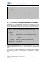
5.7. Set One GPIO Build-in Resistor Status of the Handle
Function OSAL_GPIO_DevSetONEPIN_PULL_STATUS is used to modify the build-in resistor
status of a GPIO controlled by the handle. There are three status options to choose from: pull-up,
pull-down, and high resistance, so if other status functions are selected, errors will be returned.
Function:Int OSAL_GPIO_DevSetONEPIN_PULL_STATUS(__hdle devpin,
__u32
set_pull_status, const char *gpio_name);
Parameters:
Devpin
GPIO control handle, originating from GPIO request function
Set_pull_status
Set the build-in resistor status: 0—high resistance, 1—pull up,
2—pull down
gpio_name
GPIO name,originating from configuration script
Returned Value: if succeed, return 0;
if fail, return -1.
If the handle controls more than one GPIO, the gpio_name helps to narrow down to a specific
GPIO. The GPIO name either comes from the configuration file, or is a user-defined character
string.
Here takes twi_para as an example to demonstrate how to set the GPIO build-in resistor attribute:
suppose the handle is gpio_hd, so in order to change the twi_scl build-in resistor to pull-down
status:
System Configuration and GPIO Management V1.01
Copyright © 2011 Allwinner Technology. All Rights Reserved.
April 22, 2011
37
Allwinner Technology CO., Ltd.
{
int ret;
ret = OSAL_GPIO_DevSetONEPIN_PULL_STATUS (gpio_hd, 2, “twi_scl”);
return ret;
}
The second parameter “2” means the resistor is pulled down. Except 0/1/2, other parameters are
invalid.
If the handle controls only one GPIO, “0” instead of the GPIO name can be written to the GPIO
name. For example, if there is only one GPIO named twi_scl in twi_para, following method is
adoptable:
{
int ret;
ret = OSAL_GPIO_DevSetONEPIN_PULL_STATUS (gpio_hd, 2, 0);
return ret;
}
But if there are more than one GPIO in twi_para, write “0” to the third parameter will lead to
errors.
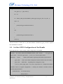
5.8. Set One GPIO Driver Strength of the Handle
The function GPIO_DevSetONEPIN_DRIVER_LEVEL_STATUS can be used to modify the driver
strength of a GPIO controlled by the handle. The driver strength refers to the GPIO ability to drive
external devices. The stronger the driver strength, the stronger the ability to change the level, and
the steeper the waves will be, but it may lead to overshoot, whereas weaker driver strength has
flatter wave, more time-consuming, but will not render overshoot. Even though Level 1 is suitable
System Configuration and GPIO Management V1.01
Copyright © 2011 Allwinner Technology. All Rights Reserved.
April 22, 2011
38
Allwinner Technology CO., Ltd.
for most cases, other driver strength levels may be required by some demanding devices.
Function : Int GPIO_DevSetONEPIN_DRIVER_LEVEL_STATUS(__hdle devpin,
__u32 set_driver_level, const char *gpio_name);
Parameters:devpin
GPIO control handle, originating from GPIO request function
set_driver_level
set the driver strength level: level 0~level 3
gpio_name
GPIO name,originating from configuration script
Returned Value: if succeed, return 0;
if fail, return -1.
This function resembles OSAL_GPIO_DevSetONEPIN_PULL_STATUS in parameters and usage,
excluding the second parameter.
Here are two examples illustrating how to modify the driver strength of a GPIO.
Supposing the GPIO handle gpio_hd controls two GPIOs of twi_para: twi_scl and twi_sda, now to
modify the twi_scl driver strength to Level 3:
{
int ret;
ret = OSAL_GPIO_DevSetONEPIN_PULL_STATUS (gpio_hd, 3, “twi_scl”);
return ret;
}
And following is a user-defined GPIO, to modify its driver strength from Level 1 to Level 2:
System Configuration and GPIO Management V1.01
Copyright © 2011 Allwinner Technology. All Rights Reserved.
April 22, 2011
39
Allwinner Technology CO., Ltd.
{
int ret;
user_gpio_set_t gpio_info;
__hdle
gpio_hd;
gpio_info.port = 1;
// use Port A
gpio_info.port_num = 14;
//use the 14th pin of Port A
gpio_info.mul_sel = 1;
//set to output
gpio_info.pull = 1;
//the resistor is pulled up by default.
gpio_info.drv_level = 1;
//the driver strength is Level 1 by default.
gpio_info.data
//output high level by default
= 1;
gpio_hd = OSAL_GPIO_Request(&gpio_info, 1); //only request one GPIO
if(!gpio_hd)
{
return -1;
}
ret = OSAL_GPIO_DevSetONEPIN_PULL_STATUS (gpio_hd, 2, 0);
return ret;
}
5.9. Read One GPIO Level of the Handle
Function OSAL_GPIO_DevREAD_ONEPIN_DATA can be used to read the level of an input GPIO:
if the returned value is 0, it is low level; if the returned value is 1, it is high level; if the returned
value is -1, it means the current GPIO is not in INPUT status.
Function:Int OSAL_GPIO_DevREAD_ONEPIN_DATA (__hdle devpin, const char
*gpio_name);
Parameters:devpin
gpio_name
GPIO control handle,originating from GPIO request function
GPIO name,originating from configuration script or customization
Returned Value:if return 1, high level;
System Configuration and GPIO Management V1.01
if return 0, low level;
Copyright © 2011 Allwinner Technology. All Rights Reserved.
April 22, 2011
if return -1, the GPIO is not in input status.
40
Allwinner Technology CO., Ltd.
Supposing the handle gpio_hd controls two GPIOs of twi_para: sda and scl, to read their port
levels, following method can be adopted:
{
int ret1, ret2;
ret1 = OSAL_GPIO_DevREAD_ONEPIN_DATA(gpio_hd, “twi_scl”);
ret2 = OSAL_GPIO_DevREAD_ONEPIN_DATA(gpio_hd, “twi_sda”);
return 0;
}
Obviously, both returned values ret1 and ret2 will be -1 in that they are in non-input status.
Following code exemplifies how to read the port level of a customized GPIO:
System Configuration and GPIO Management V1.01
Copyright © 2011 Allwinner Technology. All Rights Reserved.
April 22, 2011
41
Allwinner Technology CO., Ltd.
{
int ret;
user_gpio_set_t gpio_info;
__hdle
gpio_hd;
gpio_info.port = 1;
//use Port A
gpio_info.port_num = 14;
//use the 14th pin of Port A
gpio_info.mul_sel = 0;
//set to input
gpio_info.pull = 1;
//the resistor is pulled up by default;
gpio_info.drv_level = 1;
//the driver strength is Level 1 by default;
gpio_info.data
//output high level by default (invalid);
= 1;
gpio_hd = OSAL_GPIO_Request(&gpio_info, 1); //only request one GPIO
if(!gpio_hd)
{
return -1;
}
ret = OSAL_GPIO_DevREAD_ONEPIN_DATA(gpio_hd, 0);
(1)
OSAL_GPIO_DevSetONEPIN_IO_STATUS(gpio_hd, 1, 0);
ret = OSAL_GPIO_DevREAD_ONEPIN_DATA(gpio_hd, 0);
(2)
return 0;
}
In the example above, OSAL_GPIO_DevREAD_ONEPIN_DATA is called twice:
(1) Since the PA14 is set to input initially, its level can be read;
(2) Since PA14 is then modified to output, so its level cannot be read.
Just as other functions mentioned above, the second parameter in this function can be written to
“0” if there is only one GPIO controlled by the handle, otherwise, it’s should be a specific GPIO
name.
System Configuration and GPIO Management V1.01
Copyright © 2011 Allwinner Technology. All Rights Reserved.
April 22, 2011
42
Allwinner Technology CO., Ltd.
5.10. Set One GPIO Port Level of the Handle
The function OSAL_GPIO_DevWRITE_ONEPIN_DATA can be used to modify the port level of
an OUTPUT GPIO to high level (1) or low level (0). However, if the GPIO is not in output status,
this function is invalid, and “-1” will be returned.
{
int ret1, ret2;
ret1 = OSAL_GPIO_DevWRITE_ONEPIN_DATA(gpio_hd, 1, “twi_scl”);
ret2 = OSAL_GPIO_DevWRITE_ONEPIN_DATA(gpio_hd, 0, “twi_sda”);
return 0;
}
Following example demonstrates how to modify a GPIO output level.
Supposing the GPIO handle controls the two GPIO of twi_para: twi_sda and twi_scl, to modify
their output level:
Function : Int OSAL_GPIO_DevWRITE_ONEPIN_DATA(__hdle devpin, __u32
value_to_gpio, const char *gpio_name);
Parameters:devpin
GPIO control handle,originating from GPIO request function
value_to_gpio
gpio_name
set the output level value: 0—low level, 1—high level
GPIO name, originating from configuration script or customization
Returned Value: if succeed, return0;
if fail, return -1.
Obviously, this function cannot be successfully called since neither twi_sda nor twi_scl is output,
and a feasible method is to modify their port level after altering two GPIOs to output.
System Configuration and GPIO Management V1.01
Copyright © 2011 Allwinner Technology. All Rights Reserved.
April 22, 2011
43
Allwinner Technology CO., Ltd.
{
int ret1, ret2;
OSAL_GPIO_DevSetONEPIN_IO_STATUS(gpio_hd, 1, “twi_scl”);
OSAL_GPIO_DevSetONEPIN_IO_STATUS(gpio_hd, 1, “twi_sda”);
ret1 = OSAL_GPIO_DevWRITE_ONEPIN_DATA(gpio_hd, 1, “twi_scl”);
ret2 = OSAL_GPIO_DevWRITE_ONEPIN_DATA(gpio_hd, 0, “twi_sda”);
return 0;
}
By calling function OSAL_GPIO_DevSetONEPIN_IO_STATUS, the GPIO are altered to output,
and then set twi_scl to high level and twi_sda to low level by calling
OSAL_GPIO_DevWRITE_ONEPIN_DATA.
If there is only one GPIO (PA14) controlled by the handle, the gpio_name can be empty, as shown
below:
System Configuration and GPIO Management V1.01
Copyright © 2011 Allwinner Technology. All Rights Reserved.
April 22, 2011
44
Allwinner Technology CO., Ltd.
{
int ret;
user_gpio_set_t gpio_info;
__hdle
gpio_hd;
gpio_info.port = 1;
//use Port A
gpio_info.port_num = 14;
//use the 14th pin of PortA
gpio_info.mul_sel = 1;
//set to output
gpio_info.pull = 1;
//build-in resistor is pulled up
gpio_info.drv_level = 1;
//driver strength is Level 1
gpio_info.data
//output high level
= 1;
gpio_hd = OSAL_GPIO_Request(&gpio_info, 1); // request only one GPIO
if(!gpio_hd)
{
return -1;
}
ret = OSAL_GPIO_DevWRITE_ONEPIN_DATA(gpio_hd, 0, 0);
(1)
OSAL_GPIO_DevSetONEPIN_IO_STATUS(gpio_hd, 0, 0);
ret = OSAL_GPIO_DevWRITE_ONEPIN_DATA(gpio_hd, 1, 0);
(2)
return 0;
}
When requested, PA14 is set to output, high level. By calling function (1), it is set to output low
level, and then it’s set to input, making the port level unconfigurable, so when function (2) is
called to set it to high level, “-1” is returned because it is not in output status.
System Configuration and GPIO Management V1.01
Copyright © 2011 Allwinner Technology. All Rights Reserved.
April 22, 2011
45
Allwinner Technology CO., Ltd.
5.11. The Handle in GPIO Management
5.11.1. What Handles are Used for?
The handle is only an address pointing to a memory area that stores some valid data, such as the
file pointer.
Handles are used in GPIO management for GPIO safety, especially in cases where GPIO are
multiplexed. For example, if PC0 can be used by both NAND and Card, which has the access? A
conflict check mechanism in GPIO management helps to figure out the question: if PC0 is not
used, NAND can access it on request, and before it is released by NAND, it cannot be accessed by
Card.
This mechanism helps in three aspects:
1) Avoid conflict of GPIO access among modules;
2) Avoid conflict between module function and IO function;
3) Avoid conflict between IO input and IO output;
5.11.2. Avoid Conflict of GPIO Access among Modules
Actually, both request and handles are necessary in GPIO management.
Without the request, the Card can access PC0 any time, even when PC0 is used by NAND, and
that may render errors in NAND. Likewise, if NAND accesses PC0 when it’s used by Card, errors
may occur to Card.
If there is request, but no handles, it seems that NAND can directly control the GPIO with
configuration script data (as shown below), but when PC0 is released without the handle, it’s hard
to know which module controlled PC0.
System Configuration and GPIO Management V1.01
Copyright © 2011 Allwinner Technology. All Rights Reserved.
April 22, 2011
46
Allwinner Technology CO., Ltd.
{
user_gpio_set_t gpio_info[1];
gpio_info.port = 3;
// use Port C
gpio_info.port_num = 0;
//use the 0 pin of Port C
gpio_info.mul_sel = 2;
// used for NAND
gpio_info.pull = 1;
// build-in resistor is pulled up
gpio_info.drv_level = 1;
// driver strength is Level 1
OSAL_GPIO_Request(gpio_info, 1);
return 0;
}
Since the handle is not required to be returned on GPIO request, Card can request PC0 as well,
even when PC0 is used by NAND:
{
user_gpio_set_t gpio_info[1];
gpio_info.port = 3;
//use Port C
gpio_info.port_num = 0;
// use the 0 pin of Port C
gpio_info.mul_sel = 3;
//used for card
gpio_info.pull = 1;
//build-in resistor is pulled up
gpio_info.drv_level = 1;
//driver strength is Level 1
OSAL_GPIO_Request(gpio_info, 1);
return 0;
}
Since PC0 is used by NAND, the card request will fail, so in that case, Card may choose to
mandatorily release PC0 from NAND, which will bring about errors to NAND:
System Configuration and GPIO Management V1.01
Copyright © 2011 Allwinner Technology. All Rights Reserved.
April 22, 2011
47
Allwinner Technology CO., Ltd.
{
user_gpio_set_t gpio_info[1];
gpio_info.port = 3;
//use Port C
gpio_info.port_num = 0;
// use the 0 pin of Port C
gpio_info.mul_sel = 3;
//used for card
gpio_info.pull = 1;
//build-in resistor is pulled up
gpio_info.drv_level = 1;
//driver strength is Level 1
OSAL_GPIO_Release(gpio_info, 0);
return 0;
}
To settle these problems, handles can be introduced in for the GPIO management: when PC0 is
accessible and requested by NAND, NAND will get a handle that controlling PC0, which cannot
be forcefully released by other modules like Card.
5.11.3. Avoid Conflict between Modules and IO
In Linux OS, the port level can be easily set and read through a function, but this is based on the
premises that the GPIO is not used at that time, otherwise, errors may occur. For example, if the
PC0 level is read when it is used by NAND, errors may occur to NAND because this operation
will alter PC0 function to input.
A solution is to request the PC0 handle before operating PC0: if the handle cannot be requested, it
means PC0 is used and not accessible. If operation is made to it forcefully, errors may occur.
However, with handles introduced in the GPIO management, if the PC0 handle cannot be
requested, it cannot be operated.
5.11.4. Avoid Conflict between IO Input and IO Output
The IO conflict is similar to that of module conflict.
Here takes PC0 as an example to illustrate: Module A wants to read PC0 level, and conducts
different operations at high level and low level, whereas Module B wants to alter PC0 level,
output high level and low level at different time. If two modules operate at the same time, errors
may occur, therefore, handles can be introduced to settle the conflict.
System Configuration and GPIO Management V1.01
Copyright © 2011 Allwinner Technology. All Rights Reserved.
April 22, 2011
48
Allwinner Technology CO., Ltd.
6. Declaration
This Configuration System and GPIO Management is the original work and copyrighted property
of Allwinner Technology (“Allwinner”). Reproduction in whole or in part must obtain the written
approval of Allwinner and give clear acknowledgement to the copyright owner.
The information furnished by Allwinner is believed to be accurate and reliable. Allwinner reserves
the right to make changes in circuit design and/or specifications at any time without notice.
Allwinner does not assume any responsibility and liability for its use. Nor for any infringements of
patents or other rights of the third parties which may result from its use. No license is granted by
implication or otherwise under any patent or patent rights of Allwinner. This documentation
neither states nor implies warranty of any kind, including fitness for any particular application.
System Configuration and GPIO Management V1.01
Copyright © 2011 Allwinner Technology. All Rights Reserved.
April 22, 2011
49