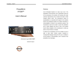
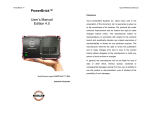
1
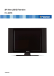
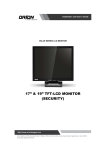
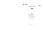
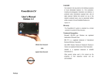
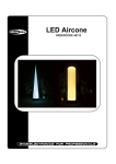
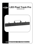
LED Powerbrick Set V2
ORDERCODE 41322
Congratulations!
You have bought a great, innovative product from Showtec.
The Showtec LED Powerbrick Set brings excitement to any venue. Whether you want simple plug-&-play
action or a sophisticated DMX show, this product provides the effect you need.
You can rely on Showtec, for more excellent lighting products.
We design and manufacture professional light equipment for the entertainment industry.
New products are being launched regularly. We work hard to keep you, our customer, satisfied.
For more information: [email protected]
You can get some of the best quality, best priced products on the market from Showtec.
So next time, turn to Showtec for more great lighting equipment.
Always get the best -- with Showtec !
Thank you!
Showtec
Showtec LED Powerbrick Set™ Product Guide
Warning..…...................................................................................……………………………………………………….. 2
Safety-instructions………………………………………………………………………………………………………… 2
Operating Determinations……………………………………………………………………………………………… 3
Description..…..............................................................................……….……………………………………………… 4
Features and Overview ………………………………...….……………….………….……….……….…………….. 4
Backside…………………………………………………...…...….……………….…………………...…………………. 4
Installation...............................................................................…...………………………………………….………..…. 5
Set Up and Operation.....................................................................……..……………………………………………… 5
1) Connected separate……...........................................……..………………………………………………….…. 5
2) Connected on top of eachother by using the supplied brackets..............................………………..….. 5
3) Connected Side by Side...........................................……..………………………………………………………. 5
Functions……………………………………………………………………………………………………………………. 7
Stand-alone ………………………………………………………………..……………….…….………………… 7
Connection Stand-alone…………………………………………….…………………………………………… 10
DMX Controlled ….………………………………………………………………….…….…….………………….. 10
Connection DMX …………..…………..………………………………………………………..…………………. 14
Illuminance Distribution………..…………………………………………………………….……………………………… 15
Candle Power distribution.............................................................…………………….………….……………….. 16
Maintenance...................................................................................………..………….…….………………………….. 17
Changing the Fuse........................................................................…………………….………………………..…... 17
Troubleshooting............................................................................………………….………………….………………... 17
Product Specifications.................................................................……………….…….………………………………... 18
1
WARNING
CAUTION!
Keep this device away from rain and moisture!
FOR YOUR OWN SAFETY, PLEASE READ THIS USER MANUAL CAREFULLY
BEFORE YOUR INITIAL START-UP!
SAFETY INSTRUCTIONS
Every person involved with the installation, operation and maintenance of this device has to:
be qualified
follow the instructions of this manual
CAUTION! Be careful with your operations.
With a dangerous voltage you can suffer
a dangerous electric shock when touching the wires!
Before your initial start-up, please make sure that there is no damage caused by transportation. Should there
be any, consult your dealer and do not use the device.
To maintain perfect condition and to ensure a safe operation, it is absolutely necessary for the user to follow
the safety instructions and warning notes written in this manual.
Please consider that damages caused by manual modifications to the device are not subject to warranty.
This device contains no user-serviceable parts. Refer servicing to qualified technicians only.
IMPORTANT:
The manufacturer will not accept liability for any resulting damages caused by the non-observance
of this manual or any unauthorized modification to the device.
Never let the power-cord come into contact with other cables! Handle the power-cord and all
connections with the mains with particular caution!
Never remove warning or informative labels from the unit.
Never leave any cables lying around.
Do not insert objects into air vents.
Do not open the device and do not modify the device.
Do not connect this device to a dimmerpack.
Do not shake the device. Avoid brute force when installing or operating the device.
Do not switch the device on and off in short intervals, as this would reduce the system’s life.
Only use device indoor, avoid contact with water or other liquids.
Only operate the fixture after having checked that the housing is firmly closed and all screws are
tightly fastened.
Only operate the device after having familiarized with its functions.
Avoid flames and do not put close to flammable liquids or gases.
Always keep case closed while operating.
Always allow free air space of at least 50 cm around the unit for ventilation.
Always disconnect power from the mains, when device is not used or before cleaning! Only handle
the power-cord by the plug. Never pull out the plug by tugging the power-cord.
2
Make sure that the device is not exposed to extreme heat, moisture or dust.
Make sure that the available voltage is not higher than stated on the rear panel.
Make sure that the power-cord is never crimped or damaged. Check the device and the powercord from time to time.
If device is dropped or struck, disconnect mains power supply immediately. Have a qualified
engineer inspect for safety before operating.
If the device has been exposed to drastic temperature fluctuation (e.g. after transportation), do not
switch it on immediately. The arising condensation water might damage your device. Leave the
device switched off until it has reached room temperature.
If your Showtec device fails to work properly, discontinue use immediately. Pack the unit securely
(preferably in the original packing material), and return it to your Showtec dealer for service.
The user is responsible for correct positioning and operating of the LED Powerbrick. The manufacturer
will not accept liability for damages caused by the misuse or incorrect installation of this device.
For adult use only. The device must be installed out of the reach of children. Never leave the unit
running unattended.
For replacement use fuses of same type and rating only.
Repairs, servicing and electric connection must be carried out by a qualified technician.
WARRANTY: Till one year after date of purchase.
OPERATING DETERMINATIONS
If this device is operated in any other way, than the one described in this manual, the product may suffer
damages and the warranty becomes void.
Any other operation may lead to dangers like short-circuit, burns, electric shock, lamp explosion, crash etc.
You endanger your own safety and the safety of others!
Rigging
Please follow the European and national guidelines concerning rigging, trussing and all other safety issues.
Do not attempt the installation yourself !
Always let the installation be carried out by an authorized dealer !
Procedure:
If the projector is lowered from the ceiling or high joists, professional trussing systems have to be used.
Use a clamp to mount the projector, with the mounting-bracket, to the trussing system.
The projector must never be fixed swinging freely in the room.
The installation must always be secured with a safety attachment, e.g. an appropriate safety net or
safety-cable.
When rigging, derigging or servicing the projector, always make sure, that the area below the
installation place is blocked and staying in the area is forbidden.
Improper installation can cause serious damage to people and property !
3
Description of the device
Features
The LED Powerbrick Set is a LED system from Showtec.
• Powerbrick set contains 4 Powerbricks, one controller, power leads, DMX leads.
• Ultra bright LED
• First grade aluminum body construction
• Unlimited colors
• Low power consumption
• Low heat design, great for long time operation.
• Lifetime: 100.000 hours
NOTE: Knowledge of DMX is required to fully utilize this unit.
Overview
Fig. 1
Backside
Fig. 2
Fig. 3
1) 3-pin DMX signal connector (OUT)
2) 3-pin DMX signal connector (IN)
3) 5-pin DMX signal connector (OUT)
4) 5-pin DMX signal connector (IN)
5) IEC Connector + Fuse
6) LCD Display
7) EXIT
8) SET
9) UP
10) DOWN
4
Installation
Remove all packing materials from the LED Powerbrick Set. Check that all foam and plastic padding is
removed. Connect all cables.
Always disconnect from electric mains power supply before cleaning or servicing.
Damages caused by non-observance are not subject to warranty.
Set Up and Operation
Before plugging the unit in, always make sure that the power supply matches the product specification
voltage. Do not attempt to operate a 120V specification product on 230V power, or vice versa.
Note : Link all cables before connecting electric power.
You have 3 possibilities to set up your LED Powerbrick Set:
1) Separate
2) Connected on top of eachother by using the supplied brackets
Bracket
Mounting the separate Powerbricks
Backside connection
3) Connected Side by Side
Be sure to put the devices next to eachother and slide Pin A1 in hole B1, do the same for pin A2 in hole B2.
Then slide the first device in the direction of C. The last step is securing the devices at the back by using clasp
D and turning it clockwise to tighten the locking mechanism.
5
Be sure to put the small cube E and the aluminum section together in the small slot.
Backside connection of 4 LED Powerbricks
Connecting the entire LED Powerbrick system to a Truss system.
6
FUNCTIONS:
There are 3 options to operate the LED Powerbrick: Stand-alone
Master / Slave
DMX Mode
After completing your settings, be sure to unplug the Powerbricks and the controller, otherwise errors could
occur.
This way you reset the entire system, but your settings keep stored in the memory of the controller.
Stand-alone
1. The device will start test-mode.
2. Press the Up/Down button until the display shows: 17. System Mode.
3. Press the Set button to enter the menu.
4. Enter the amount of tubes you are using.
5. For Stand-alone you have to use DMX Channel: 0, then press the Set Up-button again.
6. The LCD now shows “Set Address YES”; press SETUP-Button (=NO) to keep your previous settings,
or YES (=Up-Button) to store your choice. The LED Tubes will light up.
7. Now your unit is a stand-alone. You will find all the pre-programmed scenes below.
Menu
1. Static RED
2. Static GREEN
3. Static YELLOW
4. Static BLUE
5. Static PURPLE
6. Static CYAN
7. Static WHITE
8. Color Change
9. Flow 1 (FF)
10. Flow 2 (REW)
11. Flow 3 (FF/REW)
12. 2 Color Chase
13. Multi-Color Chase
14. Fade Change
15. 2 Color Fade Chase
16. Auto Run
17. System Mode
Function Set
Function Set
Function Set
Function Set
Function Set
Function Set
Function Set
Function Set
Function Set
Function Set
Function Set
Function Set
Function Set
Function Set
Function Set
Function Set
Function Set
When “Function Set” appears in the LCD, then you are able to make some extra settings: Dimmer, Run
Speed, Flash Freq, etc.
7
1. Static RED
Function Set : Gray Level 0-100 (1X Set Up)
Flash Freq 0-100 (2X Set Up)
Exit :
Return to the Mode Menu
2. Static GREEN
Function Set : Gray Level 0-100 (1X Set Up)
Flash Freq 0-100 (2X Set Up)
Exit :
Return to the Mode Menu
3. Static YELLOW
Function Set : Gray Level 0-100 (1X Set Up)
Flash Freq 0-100 (2X Set Up)
Exit :
Return to the Mode Menu
4. Static BLUE
Function Set : Gray Level 0-100 (1X Set Up)
Flash Freq 0-100 (2X Set Up)
Exit :
Return to the Mode Menu
5. Static PURPLE
Function Set : Gray Level 0-100 (1X Set Up)
Flash Freq 0-100 (2X Set Up)
Exit :
Return to the Mode Menu
6. Static CYAN
Function Set : Gray Level 0-100 (1X Set Up))
Flash Freq 0-100 (2X Set Up)
Exit :
Return to the Mode Menu
7. Static WHITE
Function Set : Gray Level 0-100 (1X Set Up)
Flash Freq 0-100 (2X Set Up)
Exit :
Return to the Mode Menu
8. Color Change
Function Set : Run Speed 0-100 (1X Set Up)
Flash Freq 0-100 (2X Set Up)
Color Sort 0-20 (3X Set Up)
Run Times 0-20 (4X Set Up)
Exit :
Return to the Mode Menu
9. Flow 1 (FF)
Function Set : Run Speed 0-100 (1X Set Up)
Flash Freq 0-100 (2X Set Up)
Color Sort 0-20 (3X Set Up)
Run Times 0-20 (4X Set Up)
Exit :
Return to the Mode Menu
10. Flow 2 (REW)
Function Set : Run Speed 0-100 (1X Set Up)
Flash Freq 0-100 (2X Set Up)
Color Sort 0-20 (3X Set Up)
Run Times 0-20 (4X Set Up)
Exit :
Return to the Mode Menu
8
11. Flow 3 (FF/REW)
Function Set : Run Speed 0-100 (1X Set Up)
Flash Freq 0-100 (2X Set Up)
Color Sort 0-20 (3X Set Up)
Run Times 0-20 (4X Set Up)
Exit :
Return to the Mode Menu
12. 2 Color Chase
Function Set : Run Speed 0-100 (1X Set Up)
Flash Freq 0-100 (2X Set Up)
Color Sort 0-20 (3X Set Up)
Run Times 0-20 (4X Set Up)
Exit :
Return to the Mode Menu
13. Multi-Color Chase
Function Set : Run Speed 0-100 (1X Set Up)
Flash Freq 0-100 (2X Set Up)
Color Sort 0-20 (3X Set Up)
Run Times 0-20 (4X Set Up)
Exit :
Return to the Mode Menu
14. Fade Change
Function Set : Run Speed 0-100 (1X Set Up)
Flash Freq 0-100 (2X Set Up)
Color Sort 0-20 (3X Set Up)
Run Times 0-20 (4X Set Up)
Exit :
Return to the Mode Menu
15. 2 Color Fade Chase
Function Set : Run Speed 0-100 (1X Set Up)
Flash Freq 0-100 (2X Set Up)
Color Sort 0-20 (3X Set Up)
Run Times 0-20 (4X Set Up)
Exit :
Return to the Mode Menu
16. Auto Run
17. System Mode
Function Set : Channels / Pixel (1X Set Up)
DMX START Channel 0-510 (2X Set Up)
Master / Slave (3X Set Up)
Pixels / Tube (4X Set Up)
Tubes Qty (5X Set Up)
Exit :
Return to the Mode Menu
In menu 8 - 15 you are also able to change the color of the chase or flow.
There are 20 available color varieties.
Channels / Pixel: you can choose 3, 4 or 5 channels per pixel
Pixels / Tube: you can choose different the sections (1/5 – 4)
• 1/5 means all the 4 LED Powerbricks are as one
• 1 means one LED Powerbrick is 1 secion
• 2 means each LED Powerbrick has 2 secions
• 4 means each LED Powerbrick has 4 secions
Tubes Qty: Choose the number of the LED Powerbricks to be controlled.
9
Connection Stand-alone
DMX Controlled
1. The device will start test-mode.
2. Press the Up/Down button until the display shows: 17. System Mode.
3. Press the Set button to enter the menu.
4. Enter the amount of tubes you are using.
5. For DMX Controlled you have to use DMX Channel: 1-510, then press the Set Up-button again.
6. The LCD now shows “Set Address YES”; press SETUP-Button (=NO) to keep your previous settings,
or YES (=Up-Button) to store your choice.
7. Now your unit is DMX-Controlled. You will find all the pre-programmed scenes below.
There are 12 possibilities for working in DMX mode; See page 11 – 14 for all Modes
10
Option 1
CH/Pixel: 3
Pixels/Tube: 1/5
Total Channels: 3
CH1: Red
CH2: Green
CH3: Blue
Option 2
CH/Pixel: 3
Pixels/Tube: 1
Total Channels: 12
CH1: Red
CH2: Green
CH3: Blue
CH4: Red
.
.
CH12: Blue
Option 3
CH/Pixel: 3
Pixels/Tube: 2
Total Channels: 24
CH1: Red
CH2: Green
CH3: Blue
CH4: Red
.
.
CH24: Blue
Option 4
CH/Pixel: 3
Pixels/Tube: 4
Total Channels: 48
CH1: Red
CH2: Green
CH3: Blue
CH4: Red
.
.
CH48: Blue
11
Option 5
CH/Pixel: 4
Total Channels: 4
Pixels/Tube: 1/5
CH1: Master Dimmer
CH2: Red
CH3: Green
CH4: Blue
Option 6
CH/Pixel: 4
Total Channels: 16
Pixels/Tube: 1
CH1: Master Dimmer 1st Powerbrick
CH2: Red
CH3: Green
CH4: Blue
CH5: Master Dimmer 2nd Powerbrick
CH6: Red
.
.
CH16: Blue
Option 7
CH/Pixel: 4
Total Channels: 32
Pixels/Tube: 2
CH1: Master Dimmer 1st Powerbrick (LED 1+2)
CH2: Red
CH3: Green
CH4: Blue
CH5: Master Dimmer 1nd Powerbrick (LED 3+4)
CH6: Red
.
.
CH24: Blue
Option 8
CH/Pixel: 4
Total Channels: 64
Pixels/Tube: 4
CH1: Master Dimmer 1st Powerbrick (LED1)
CH2: Red
CH3: Green
CH4: Blue
CH5: Master Dimmer 1nd Powerbrick (LED 2)
CH6: Red
.
.
CH48: Blue
12
Option 9
CH/Pixel: 5
Pixels/Tube: 1/5
Total Channels: 5
CH1: Master Dimmer
CH2: Strobe
CH3: Red
CH4: Green
CH5: Blue
Option 10
CH/Pixel: 5
Pixels/Tube: 1
Total Channels: 20
CH1: Master Dimmer 1st Powerbrick
CH2: Strobe
CH3: Red
CH4: Green
CH5: Blue
CH6: Master Dimmer 2nd Powerbrick
CH7: Strobe
CH8: Red
.
.
CH20: Blue
Option 11
CH/Pixel: 5
Pixels/Tube: 2
Total Channels: 40
CH1: Master Dimmer 1st Powerbrick (LED 1+2)
CH2: Strobe
CH3: Red
CH4: Green
CH5: Blue
CH6: Master Dimmer 1nd Powerbrick (LED 3+4)
CH7: Strobe
CH8: Red
.
.
CH40: Blue
13
Option 12
CH/Pixel: 5
Pixels/Tube: 4
Total Channels: 80
CH1: Master Dimmer 1st Powerbrick (LED 1)
CH2: Strobe
CH3: Red
CH4: Green
CH5: Blue
CH6: Master Dimmer 1st Powerbrick (LED 2)
CH7: Strobe
CH8: Red
.
.
CH80: Blue
Connection DMX
You can control the LED Powerbrick with 3, 4 or 5 channels:
• 3 channel: rRed, Green, Blue.
• 4 channel: Master dimmer, Red, Green, Blue.
• 5 channel: Master dimmer, strobe, Red, Green, Blue.
14
Illuminance Distribution
1.0m.
0.0m.
1.0m.
Illuminance
15
16
Maintenance
The LED Powerbrick Set requires almost no maintenance. However, you should keep the unit clean.
Disconnect the mains power supply, and then wipe the cover with a damp cloth. Do not immerse in liquid.
Keep connections clean. Disconnect electric power, and then wipe the connections with a damp cloth.
Make sure connections are thoroughly dry before linking equipment or supplying electric power.
Replacing a Fuse
Power surges, short-circuit or inappropriate electrical power supply may cause a fuse to burn out. If the fuse
burns out, the product will not function whatsoever. If this happens, follow the directions below to do so.
1. Unplug the unit from electric power source.
2. Insert a flat-head screwdriver into a slot in the fuse cover. Gently pry up the fuse cover. The fuse will
come out.
3. Remove the broken fuse. If brown or unclear, it is burned out.
4. Insert the replacement fuse into the holder where the old fuse was. Reinsert the fuse cover.
Be sure to use a fuse of the same type and specification. See the product specification label for details.
Troubleshooting
Showtec LED Powerbrick Set
This troubleshooting guide is meant to help solve simple problems.
If a problem occurs, carry out the steps below in sequence until a solution is found. Once the unit operates
properly, do not carry out following steps.
If the light effect does not operate properly, refer servicing to a technician.
1. If the device does not operate properly, unplug the device.
2. Check the fuse, power from the wall, all cables etc.
3. If all of the above appears to be O.K., plug the unit in again.
4. If you are unable to determine the cause of the problem, do not open the LED Powerbrick Set, as this
may damage the unit and the warranty will become void.
5. Return the device to your Showtec dealer.
17
Product Specification
Model: Showtec LED Powerbrick Set
4 x Powerbrick
Working Voltage: 48V DC
Max. Power: 18W
Colors: 16.7million
Light Source: 1W RGB LED
12 LEDs (4 Red, 4 Green, 4 Blue)
Beam Angle: 25°
Housing: Aluminum body in black
Data connector: 4-pin XLR
Weight: 1,5 kg
1 x Powerbrick controller
Voltage: AC 230V-50Hz (CE)
Output 48V DC
Housing: Aluminum body in black
Data connector: 4-pin XLR
Weight: 3.2 Kg
Max. ambient temperature ta: 40°C
Minimum distance:
Minimum distance from flammable surfaces: 0.5m
Minimum distance to lighted object: 1m
Design and product specifications are subject to change without prior notice.
Website: www.Highlite.nl
Email: [email protected]
18
2007 Showtec.