1
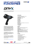
Electrostatic Discharge Simulator
user manual
A Note to Begin
Thank you for choosing the Haefely ONYX to meet your ESD testing needs. Please take a little time to
read through this user manual and familiarize yourself with the instrument controls and some potential
dangers.
We hope you have many productive years of operation from the ONYX ESD Simulator.
HAEFELY TEST AG
Document Title
Release date
Authors
Reference No.
User Manual: Electrostatic Discharge Simulator
ONYX
2010-05-21
M. Yiapanas / B. Straumann
4700551
Contents
CONTENTS .................................................................................................................. I
1
SAFETY .................................................................................................................1
1.1
General Safety Information................................................................................1
1.2
Safety Standards................................................................................................1
2
2.1
3
DESCRIPTION .......................................................................................................2
Overview............................................................................................................2
TECHNICAL DATA..................................................................................................3
3.1 Electrical data ....................................................................................................3
3.1.1 ONYX basic version.......................................................................................... 3
3.1.2 ONYX optional accessories ................................................................................ 4
3.2
Operating Conditions .........................................................................................5
3.3
Mechanical Data.................................................................................................5
3.4
Standards...........................................................................................................5
3.5
General ..............................................................................................................5
4
4.1
INITIAL OPERATION.............................................................................................6
Visual Checks .....................................................................................................6
4.2 Installation ........................................................................................................6
4.2.1 Connecting the ONYX ....................................................................................... 6
5
LOCAL OPERATION ...............................................................................................7
5.1 Power ................................................................................................................7
5.1.1 Battery power & charger .................................................................................. 7
5.1.2 AC mains adapter (optional) ............................................................................. 7
5.2 Parts ..................................................................................................................8
5.2.1 Trigger........................................................................................................... 8
5.2.2 Smart key ...................................................................................................... 8
5.2.3 Tripod ............................................................................................................ 8
5.2.4 Optical interface .............................................................................................. 9
5.2.5 Discharge tips ................................................................................................. 9
5.2.6 RC modules .................................................................................................. 10
5.3 Main menu .......................................................................................................11
5.3.1 Using the sub-menus ..................................................................................... 12
5.4 Basic operation ................................................................................................13
5.4.1 Sub-menu 1.................................................................................................. 14
5.4.2 Sub-menu 2.................................................................................................. 15
5.4.3 Sub-menu 3.................................................................................................. 16
5.5 During the test ................................................................................................ 17
5.5.1 Display .........................................................................................................17
5.6
Discharge detection and Threshold setting...................................................... 19
5.7 Test setup........................................................................................................ 20
5.7.1 Test setup example according to IEC/EN 61000-4-2 edition 2..............................20
6
ERROR MESSAGES AND SELFTEST ...................................................................... 21
6.1
Error messages................................................................................................ 21
6.2 Selftest routine................................................................................................ 22
6.2.1 Performing Selftest routine .............................................................................22
6.2.2 Troubleshooting if Selftest FAILED ...................................................................22
7
ACCESSORIES AND OPTIONS ............................................................................. 23
7.1 ONYX Accessories............................................................................................ 23
7.1.1 ONYX remote control package .........................................................................24
8
SERVICE ............................................................................................................. 25
8.1 Service ............................................................................................................ 25
8.1.1 Cleaning .......................................................................................................25
8.1.2 Battery .........................................................................................................25
8.2
9
Calibration....................................................................................................... 25
CORRECTIONS AND ADDITIONS......................................................................... 26
9.1 Addresses........................................................................................................ 26
9.1.1 International Customer Service .......................................................................26
9.1.2 USA Customer Service....................................................................................26
9.1.3 China Customer Service..................................................................................26
9.1.4 Manufacturer.................................................................................................26
9.2
Glossary of terms and Abbreviations ............................................................... 27
10
APPENDIX A .................................................................................................... 28
10.1
CE conformity ............................................................................................... 28
ONYX Electrostatic Discharge Simulator
1 Safety
1.1 General Safety Information
This warning sign is visible on the equipment. Meaning: This equipment should only be operated after
carefully reading the user manual
Throughout the user manual very important or helpful advice is presented in italics.
Safety notices that must be heeded are printed in bold type.
The earth connection of the ESD Simulator must be connected to a good earth.
If trigger is pressed without connection to earth, electrical shock may occur!
Dangerous mains voltage or high voltages are present inside the ONYX.
Before removing any covers, remove all external connection cables.
Do not open any part of the ONYX as it contains no user replaceable parts. This does not apply to the
cover used for replacement of RC module.
The ONYX should only be maintained by trained personnel.
People with heart pacemakers must not be in the vicinity of the system, when it is in operation.
Do not switch on or operate the ONYX System if an explosion hazard exists.
The system should be operated in a dry room. If condensation is visible the unit should be dried before
operating.
Never touch the Equipment Under Test (EUT), when the ONYX is operating. Establish a safety barrier
around the test setup.
If any part of the ONYX is damaged or it is possible that damage has occurred, for example during
transportation, do not switch on the unit.
This user manual is an integral part of the test system. Haefely Test AG and its sales partners refuse to
accept any responsibility for consequential or direct damage to persons and/or goods due to none
observance of instructions contained herein or due to incorrect use of the ONYX.
1.2 Safety Standards
The ONYX fulfils the requirements of IEC 61010-1.
ONYX Electrostatic Discharge Simulator
1
2 Description
2.1 Overview
Any electrical equipment can be subject to electrostatic discharges from human operators or from adjacent objects.
The electrostatic discharge simulator ONYX, reproduces this phenomenon to evaluate the performance of electrical
and electronic equipment.
There are specific test requirements that must be satisfied when conducting ESD testing. These are noted in some
detail in IEC/EN 61000-4-2, ISO 10605 and other standards.
Because of its modular design, ONYX can be adapted quickly and easily to perform testing to any ESD standard.
All ESD testing should ideally be conducted in a Faraday cage or other suitable enclosure.
For small EUT's, a test table constructed only of wood must be used, This is covered with a metallic horizontal
coupling plane which in turn is connected to a ground reference plane by 2 x 470 kOhm resistors.
The EUT should be mounted above the horizontal coupling plane on an isolation plate of 0.5mm thickness.
Vertical coupling planes are to be used to inject an ESD field into all four faces of an EUT.
Larger floor standing equipment must be treated in a similar way but have an isolation plate of 0.1 m.
2
ONYX Electrostatic Discharge Simulator
3 Technical Data
3.1 Electrical data
3.1.1 ONYX basic version
ONYX 16 output voltage range
ONYX 30 output voltage range
Voltage resolution
Polarity
Output voltage tolerance
Holding time
1kV to 16kV air discharge & contact discharge
1kV to 30kV air discharge & contact discharge
100 V steps
Positive / negative, automatic switching
± 5%
> 5s
Default Discharge electrodes
Round tip for air discharge / sharp tip for contact discharge according
to IEC 61000-4-2 & ISO 10605
Default RC module
RC module recognition
150pF / 330 Ohm according to IEC/EN 61000-4-2 edition 2,
waveform specification see table 1 below
Automatic, values shown in display & test report
Controls
Repetition frequency
Operating modes
Touch screen, Trigger key, Smart key
Single, 0.1, 0.2, 0.5, 1, 2, 5, 10 and 20 Hz (see table 3)
Manual / continuous
Discharge detection / Threshold
OFF
HV -10% … HV -90%
HV -20%
Impulse counter
1 – 9999, pre-selectable
Temperature indicator
Humidity indicator
Dew point indicator
° Celsius or ° Fahrenheit (selectable)
Relative humidity
° Celsius or ° Fahrenheit (selectable)
Interface
Fibre-optic
Battery duration
Contact discharge 30kV, 1Hz, approx. 8h
Contact discharge 16kV, 1Hz, approx. 12h
Contact discharge 8kV, 1Hz, approx. 18h
NiMH
100V – 240V, 47-63Hz, 17VA
Approx. 3.5h
Battery type
Battery charger power requirements
Battery charging time
Level
1
2
3
4
X
X
Indicated
Voltage
[kV]
2
4
6
8
16
* 30
(contact discharge mode only)
(contact discharge & air discharge single)
(fixed for air discharge auto)
First peak current
(± 15%)
Rise time tr
(± 25%)
Current @ 30ns
(± 30%)
Current @ 60ns
(± 30%)
[A]
7.5
15
22.5
30
60
112.5
[ns]
0.8
0.8
0.8
0.8
0.8
0.8
[A]
4
8
12
16
32
60
[A]
2
4
6
8
16
30
Table 1 contact discharge current waveform parameters ONYX 16 / ONYX 30 according to
IEC 61000-4-2 edition 2
* ONYX 30 only
ONYX Electrostatic Discharge Simulator
3
3.1.2 ONYX optional accessories
RC modules
150pF / 2000 Ohm
330pF / 2000 Ohm
330pF / 330 Ohm
100pF / 1500 Ohm
150pF / 150 Ohm
500pF / 500 Ohm
500pF / 5000 Ohm
xxxx pF / xxxx Ohm
according to ISO 10605, see table 2 below
according to ISO 10605, see table 2 below
according to ISO 10605, see table 2 below
various standards
various standards
various standards
various standards
customized values
Fast rise time tip
0.3ns rise time
112.5A @ 30kV peak current
Mains adapter
100V – 240V, 47-63Hz, 45VA
30kV air discharge tip
30mm diameter
RC module
First peak current
Rise time
Current @ t1
Current @ t2
330pF / 330 Ohm
[A/kV]
3.75 (+10%/-10%)
[ns]
0.7 to 1.0
150pF / 2000 Ohm
3.75 (+30%/-0%)
0.7 to 1.0
330pF / 2000 Ohm
3.75 (+30%/-0%)
0.7 to 1.0
[A/kV]
2 (± 30%)
@ t1=65ns
0.275 (± 30%)
@ t1=180ns
0.275 (± 30%)
@ t1=400ns
[A/kV]
1 [± 30%]
@ t2 = 130ns
0.15 (± 50%)
@ t2=360ns
0.15 (± 50%)
@ t2=800ns
Table 2 contact discharge current waveform parameters ONYX 16 / ONYX 30 with ISO 10605 RC modules
For RC module capacitor value > 150pF, maximum voltage / maximum frequency is limited, depending on
frequency or voltage settings. See table 3 below
RC module
capacitor value
maximum voltage
< 10Hz repetition
maximum voltage
at 10Hz repetition
maximum voltage
at 20Hz repetition
[pF]
50
100
150
200
330
500
1000
[kV]
30
30
30
30
30
30
30
[kV]
30
30
30
30
30
20
20
[kV]
30
30
30
20
15
15
10
Table 3 maximum voltage / repetition frequency
4
ONYX Electrostatic Discharge Simulator
3.2 Operating Conditions
Operating Temperature Range
Storage Temperature Range
Air humidity
Air pressure
+15…+35°C
-10…+50°C
20...80 % r.h, non condensing
86...106 kPa
3.3 Mechanical Data
Dimensions:
Weight:
Tripod screw thread
approx. W 290mm x H 270mm x D 110mm
approx. 1.7kg
¼ inch UNC (standard camera tripod screw thread)
3.4 Standards
Standards covered by ONYX
•
•
•
•
•
•
•
•
•
•
•
•
•
•
•
•
IEC/EN 61000-4-2 edition 1 + 2 (default)
ISO 10605
IEC/EN 61326
IEC/EN 61000-6-1 & -6-2
IEC 61340-3-1
GMW 3097
Ford AB/AC
ANSI C63.16
PSA B21 7110
ISO 14304
ITU-T K.20
MIL-STD-331/-464/-750/-883/-1512/-1514/-1541/-1542
RTCA/DO-160
JEDEC 22-A114
GR-78-CORE
GR-1089-CORE
and others
•
•
•
•
•
direct solar radiation
water ingress
dirty or dusty atmospheres
excessive vibration
electromagnetic interference
3.5 General
The equipment must not be
subjected to:
ONYX Electrostatic Discharge Simulator
5
4 Initial Operation
Persons with heart pacemakers must not be in the vicinity when the system is operating!
4.1 Visual Checks
During transport ONYX may be subjected to excessive shocks and vibrations, even though every care is taken by
Haefely Test AG to provide suitable packaging. Before operating the unit, check for signs of mechanical damage.
Damaged packing cases may by a sign of transport damage. Damage caused in transit must be reported to the
shipping agent immediately.
If damage to ONYX or its charging unit can be seen or is suspected, do not apply any voltage!
4.2 Installation
This equipment should only be operated in a Faraday cage or other suitable environment!
4.2.1 Connecting the ONYX
Before powering, fully charge battery using the supplied battery charger.
Connect one side of the black ground cable to earth connection (3) on the ONYX, located in front of
the trigger button, and the other to the ground system of your test setup.
Failure to make secure earth connection may result in electrical shock.
Securely place correct discharge tip (air or contact discharge, depending on your test requirement).
Power on by keeping the trigger key pressed for approx. 3 seconds.
(1)
Exchangeable discharge tip
(2)
LED light
(3)
Earth cable connection
(4)
Smart key
(5)
Trigger
(6)
Battery pack or mains adapter (optional)
(7)
Tripod connection
(8)
Optical interface
(9)
Touch screen
(10) RC module port
Fig. 1 connecting the ONYX
6
ONYX Electrostatic Discharge Simulator
5 Local Operation
5.1 Power
5.1.1 Battery power & charger
The ONYX simulator comes together with two rechargeable NiMH batteries and a battery charger.
The battery has to be either removed from the ONYX to be charged, or charged while the ONYX is not in operation.
The battery charger cable has to be connected to the battery’s charging connector, located at the base (bottom) of the
battery, and has to be correctly and securely inserted to ensure correct charging.
The indicators on the charger provide all necessary information on the status of the battery and charging as described
below:
(1) LED red “Power”: Steady light indicates that the charger is ready for use
(2) LED red “Charge”: Steady light indicates the fast charging process after connecting the battery pack
(3) LED green “Ready”: Steady light indicated that battery is fully charged. After approx 2 minutes it switches to
flashing to indicate trickle charging.
Once the battery pack is connected, the testing cycle is initiated and the green LED flashes for approx 1 minute. If
it carries on flashing and the red LED “Charge” does not light, it indicates that the battery pack is not connected
properly and maybe has an incorrect polarity
(4) LED yellow “Discharge”: Steady light indicates the discharging process after pressing the yellow button. The LED
“Ready” flashes for around 1 minute indicating the testing cycle
(5) Discharge Button: Press this button for about two seconds to start the optional discharge process for the battery
pack. Normally it is not necessary to discharge the batteries before charging
Fig. 2 charger and battery pack
To avoid deep discharge, remove battery pack from ONYX when not using it for more than one month
To avoid deep discharge due to self-discharge, battery pack should be fully charged at least once within a
year, even if unit is not in use
5.1.2 AC mains adapter (optional)
The optional AC mains adapter set can be used for powering the ONYX
from the power mains. To power the ONYX, replace the battery pack by the
mains adapter and connect it to the power supply output cable.
Fig. 3 power supply
ONYX Electrostatic Discharge Simulator
7
5.2 Parts
5.2.1 Trigger
The trigger position can be seen in figure 4.
When performing a sequence discharge event (see example section "Sub-menu 1"), the trigger needs to be kept
pressed in order to run through the complete test sequence. By releasing the trigger during a sequence, the test will
automatically stop, and will continue when the trigger is activated again.
You may also choose to select the "Trigger Lock" function from sub-menu 2, in order to lock the trigger position for
long test events.
Fig. 4 trigger and smart key
5.2.2 Smart key
The smart key’s position can be seen in figure 4 and is integrated in top part of the trigger button.
Smart key functions are defined in the sub-menu 2.
5.2.3 Tripod
The ONYX connection position for the tripod is shown in figure 5. For continuous testing the use of a tripod is
recommended. Screw thread ¼ inch UNC.
Fig. 5 tripod position
8
ONYX Electrostatic Discharge Simulator
5.2.4 Optical interface
The optional remote control package enables remote control operation of the unit, automatic generation of tests report
and uploading/downloading test sequences to/from ONYX.
The package contains:
• Fibre-optic cable 10m having RS232 converter one end and optical plug on other end
• RS232 to USB converter
• User manual including instruction set
• ONYX application software for remote control & automatic reporting
Fig. 6 optical interface
5.2.5 Discharge tips
Before touching the discharge tips to change them, switch the ONYX tester off and wait for a few
seconds so that the impulse capacitor can discharge internally.
Do not touch the tips while the “HVon” is displayed on the touch screen, indicating that the capacitor
is charged. Any contact with the test tips during this stage will result in electrostatic discharge.
The ONYX simulator is supplied with one contact and one air discharge tip. Additional tips such as 30mm air discharge
and fast rise time tips are available as an option.
The 30mm air discharge tip ensures a more stable rise time of the pulse above 15kV.
The fast rise time tip reduces the rise time of the ESD pulse down to 0.3ns.
Please refer to section "Accessories and Options" for ordering details.
Because of the sharp edge of the contact discharge tip, we highly recommend that you handle this
part with care to avoid unnecessary injuries.
Contact discharge tip
Air discharge tip
30mm air discharge tip (optional)
Fig. 7 discharge tips
ONYX Electrostatic Discharge Simulator
9
(1) The discharge tip can easily be placed or removed from
the ONYX
(2) Ensure correct tip type is used before each test
(3) We recommend that you remove the tips for the ONYX
when testing is complete and place within a safe area
to avoid damaging
Fig. 8 discharge tip position
5.2.6 RC modules
The basic version of ONYX is supplied with the 150pF / 330 Ohm IEC / ISO RC module.
Additional modules are available. Please refer to section "Accessories and Options".
To replace an RC module, remove the cover at the side of the ONYX as seen in figure 10. A small pull-out handle on
the RC module is used for pulling out the RC module from the ONYX.
Never remove the RC module while the ONYX is in operation. Switch off unit and wait at least 10
seconds before removing. Failure to do this may result in electrical shock.
Fig. 9 RC module
10
ONYX Electrostatic Discharge Simulator
5.3 Main menu
The ONYX simulator is operated via a touch screen which serves as an interface for defining, loading, and storing
tests. The figure below resembles a screenshot of the main menu.
Fig. 10 ONYX main menu
(1)
Bar graph
Displays test progress if “Alt.Polarity” and/or “Sweep U” function has been
selected
(2)
Discharge counter
Select count up " " / down " "
Set pre-selection counter 1-9999 (only if " " is selected)
Reset the counter to 0 (counter up) or the preselected value (counter down)
Set "Threshold" settings. For details see section "Discharge detection and
Threshold setting" and section "Technical Data ONYX basic version"
(3)
Repetition / frequency
Set frequency
single/auto for air discharge mode
single/0.1/0.2/0.5/1/2/5/10/20Hz for contact
discharge mode
(4)
Power Off
Keep pressed for 3 seconds to turn unit OFF
(5)
Battery
Displays remaining battery life (display only)
(6)
Sub-menu
Press to enter ONYX sub-menu 1-3
(7)
Discharge mode
Press to select discharge mode
contact discharge
air discharge
(8)
RC network
Displays current RC module (display only)
(9)
Polarity
Set/display polarity to positive or negative
(10)
Voltage
Set/display selected voltage
(11)
HVon
Displays HV status. When this is displayed, then the high voltage capacitor is
charged and any contact with the tip may cause a discharge (display only)
ONYX Electrostatic Discharge Simulator
11
5.3.1 Using the sub-menus
Press shortcut 6 (figure 10) to enter sub-menu.
Fig. 11 sub-menu
(1)
Menu Up/Down key
Use the Up/Down key to toggle between menu pages and move the selection
bar
(2)
Page
Displays the current menu page (display only)
(3)
Home
Press to return to main menu
(4)
Highlight function
This highlights the function you have moved to by using the menu up/down
keys (1). Once you have highlighted the function you wish to select, press in
the middle of the screen to enter
12
ONYX Electrostatic Discharge Simulator
5.4 Basic operation
There are various ways of performing your ESD testing depending on your exact requirement. The ONYX has been
designed in such a way to ensure flexibility and simplicity of operation.
A fast test can be performed via the main menu, or you may load a test or define a test sequence via the sub-menu
pages. The following examples will guide you through the types of tests you can perform with the ONYX, as well as the
functions of each menu function.
Select contact/air discharge and repetition frequency as described
in figure 10.
(1) Press on “+” or "-" key to switch
between positive and negative
polarity
(2) Touch on displayed value
(3) Use Left/Right keys to scroll to
the numerical value you wish to
change
(4) Use Up/Down key to change
underlined value
(5) Press “√” key to save change, or
“X” key to exit without saving
If you want to Select an “IEC level”, press on the “Select Value” at the top
right of the screen.
(1) Press “Select Value” to switch
to “Select Standard”
(2) Scroll Up/Down to select desired
level (1-4)
(3) Press “√” key to save change, or
“X” key to exit without saving
Press on the top right corner to enter and change “Counter” settings, and
to access the “Threshold” settings menu.
By accessing the “Counter” menu and pressing “√”,without manually
entering any counter values, the ONYX will automatically preset the
counter to the last saved values.
(1) Press on the top right corner to
enter the “Counter” menu
(2) Use the left/right/up/down arrow
keys to enter the desired counter
settings (1-9999), and select
counter "up/down"
(3) Press “√” to save change, or “X”
key to exit without saving
Note: Values 1-9999 only may be
entered in “count down” mode
(1) In the “Counter” menu, press on
the top right corner to enter the
“Threshold” menu
(2) Use the Up/Down arrow keys to
enter the desired Threshold level
(3) Press “√” to save change, or “X”
key to exit without saving
In "contact discharge" mode, Threshold settings are "10%...90%" or "OFF"
In "single air discharge" mode, Threshold settings are "10%…90%"
In "auto" air discharge mode, Threshold setting is fixed at "20%"
For details please see section
"Discharge Detection and Threshold
setting"
ONYX Electrostatic Discharge Simulator
13
5.4.1 Sub-menu 1
The sub-menu section enables you to change ONYX settings, define, save and open pre-defined tests, as well as view
environmental conditions, define smart key functions, display system info etc.
To enter the menu pages follow the instructions in figure 10. To scroll through menus and make selections, please use
the instructions mentioned in figure 11.
Alt.Polarity
Switch to “ON” position to activate automatic polarity switching. Polarity will toggle
when “Pulses/Steps” impulses are finished
Can be used in combination with "Sweep U" function
Sweep U
"ON" position activates the sweep voltage function
Can be used in combination with "Alt.Polarity" function
Start U
Enter the starting voltage of your "Sweep U" sequence
(1-16kV ONYX 16 / 1-30kV ONYX 30)
Delta U
Enter the voltage step of your "Sweep U" sequence
(0,1kV … 10kV / 0.1kV steps
Stop U
Final test voltage level of your "Sweep U" sequence
(1-16kV ONYX 16, 1-30kV ONYX 30)
Pulses/Step
Number of pulses per test step of your "Alt.Ploarity" and/or "Sweep U" sequence
(1 … 999)
Save Setup
Save and/or rename current setup
Note that to save a setup, you will need to overwrite one of the 8 factory-predefined
setups.
To change the name:
(1) enter “Save Setup” page
(2) touch the name displayed in the middle of the screen
(3) use the Up/Down and Left/Right keys to make name changes
(4) press “√”to save changes or “X” to exit without changing
Example of a test sequence using "Alt.Polarity and "Sweep U" function
Enter the values as displayed on
the menu page 1/3 on the left, and
return to main menu.
By pressing the trigger button the
ONYX will perform the following
test sequence:
(1) 10x impulses at +8kV
(2) 10x impulses at -8kV
(3) 10x impulses at +6kV
(4) 10x impulses at -6kV
(5) 10x impulses at +4kV
(6) 10x impulses at -4kV
(7) 10x impulses at +2kV
(8) 10x impulses at -2kV
14
ONYX Electrostatic Discharge Simulator
5.4.2 Sub-menu 2
Open Setup
Open one of 8 stored setups. As factory default, 8 IEC tests are stored (L1 to L4
contact discharge and L1 to L4 air discharge).
This predefined tests can be overwritten by customer specific setups
Trigger Lock
"ON" locks trigger position, "OFF" disables trigger lock position.
When you select "ON" position, press the trigger once to begin a test sequence. If
pressed again the test will stop
Smart key
Program the smart key function according to your testing requirements: Alternate
Polarity, Reset Counter, Tip LED, Auxiliary trigger, Report, U-step
"ALTERNATE POL"
enables you to change the polarity via the smart key
"RESET COUNTER"
resets the counter to the pre-selected value
"Tip LED"
LED can be switched on/off by the smart key
"AUX. TRIGGER"
send a trigger signal to a PC via the optical link. Can be used for example for
triggering an USB-Camera which is connected to the PC
"REPORT"
If ONYX application software is used (running on PC which is connect to ONYX via
optical link), this function is used to jump automatically to the next test point on the
generated test report
"U-STEP"
Use the smart key to increase/decrease test levels: U-2kV, U-1kV, U-0.5kV,
U-0.1kV, U+0.1kV, U+0.5kV, U+1kV, U+2kV
Self test
Performs a self test on the ONYX simulator.
Please refer to section "Error Messages and Selftest"
Tip LED
Switch tip LED ON and OFF
Temp & RH
Displays environmental temperature, relative humidity and dew point in degrees
Fahrenheit or Celsius. Use up/down keys to toggle between degrees Fahrenheit and
Celsius
System Info
Displays firmware version, serial number, model, RC module values
ONYX Electrostatic Discharge Simulator
15
5.4.3 Sub-menu 3
Backlight
Adjust backlight settings OFF to 100% (10% steps)
Contrast
Adjust contrast 0-100%
Beeper
Set key-beep to ON/OFF. Beep sound due to a failure can not be deactivated
Set to default
ONYX settings are set to default. Saved tests will NOT be reset!
English
Change display language settings to English, French, German
Auto Off
Define switch off time: OFF, 120/60/30/15 minutes
Power Off
Switch unit off
16
ONYX Electrostatic Discharge Simulator
5.5 During the test
5.5.1 Display
During a test the main menu displays the selected test parameters and provides feedback on the test status.
Fig. 12 during testing display
(1)
Bar graph
Displays sequence progress if “Alt.Polarity” and/or “Sweep U” function has
been selected.
If sequence is finished, beeper beeps thrice.
Releasing and pressing again the Trigger will reset the bar graph an restart
the sequence
(2)
Discharge counter
The display counter will count up or down depending on the settings
" " will count up, indicating the current number of discharges.
Once the trigger button is released, the test will stop. When the trigger is
pressed again, the counter will continue to count up from the previous value.
Resetting the counter is possible via the Counter menu or the smart key
" " will count down from the user preselected value, indicating the value of
the remaining discharges. When the Counter reaches “0”, the test will stop
and beeper beeps thrice. Resetting the Counter is possible via the Counter
menu or the smart key
(3)
Repetition / frequency
Displays selected frequency
(4)
Discharge mode
Displays discharge mode
(5)
RC module
Displays current RC module
(6)
IEC level
If a certain test level (L1/L2/L3/L4) according to IEC 61000-4-2 is selected, this
is indicated in the display.
Please note that according to the standard, test levels are different for air
discharge and contact discharge mode
(7)
Polarity
Displays current polarity
ONYX Electrostatic Discharge Simulator
17
(8)
Trigger Lock
If "Trigger Lock" is set to "ON" in the sub-menu 2, Trigger Lock sign is visible
in the display. If trigger is pressed once, test will be started and the sign is
highlighted. If trigger is pressed again, test will be stopped and sign is no
longer highlighted
(9)
Voltage
Displays voltage
When a valid discharge is detected, the “kV” sign is highlighted
(10)
Setup name
If a predefined setup is opened, the name is displayed.
As soon as one of the test parameters is changed, setup name will disappear
(11)
HV timeout
In air discharge mode, if the trigger is pressed ONYX will start generating high
voltage. During this time the "HVon" sign (12) is visible on the display.
If no discharge occurs within a period of 10 seconds, high voltage is switched
off automatically and the HV timeout " X " sign appears.
This not only indicates that a discharge did not occur, but also prevents
electrical shock and saves battery life
(12)
HVon
Displays HV status. When this is displayed, then high voltage is generated
and any contact with the tip may cause a discharge (display only). Tip must
not be touched by the user as long as this sign is displayed
18
ONYX Electrostatic Discharge Simulator
5.6 Discharge detection and Threshold setting
The ONYX provides appropriate feedback and warnings with regards to whether a discharge to EUT has occurred.
In contact discharge mode, whether a valid discharge occurred or not can normally only be detected by using the
"Threshold” function.
For example, doing a contact discharge test on an EUT having coated metallic enclosure, it is required that the test tip
penetrates the coating, so that a real discharge to EUT may occur. If there is no electrical contact between test tip and
EUT enclosure, there will be no discharge to the EUT. Normally, the user may not detect by himself whether there was
a discharge to EUT or not. No discharge means that EUT was in fact not tested correctly.
In air discharge mode, the user normally can detect if there was a flashover from the test tip to the EUT or not.
However, even if a flashover occurred, the energy from HV-capacitor may be discharged only partly. Depending on the
users requirements, also for air discharge mode the "Threshold" function may be useful.
Figure 13 below displays different "Threshold" levels. If for example a test is performed with a "Threshold" level of
"HV -10%", then the ONYX will check the HV-capacitor voltage level before the trigger, and compare it to the voltage
level following the release of the trigger. If the drop exceeds 10%, then the ONYX will automatically assume a valid
discharge and Counter will be changed by 1 impulse.
If the 10% is not exceeded, indicating that the HV-capacitor did not discharge to the desired level, the ONYX will
assume an invalid discharge and will issue the appropriate warnings and actions as described below.
If no valid discharge occurs then the beeper will beep once, the counter will not change value, and the test will stop.
Release and press again the trigger to restart the test.
A valid air or contact discharge is confirmed by the “kV” indication next to the selected voltage display value. Once a
valid discharge occurs, the “kV” indication is highlighted as shown in figure 12.
If “Threshold” is on "OFF" position (only possible with contact discharge mode), the ONYX will run through the test
sequence but there will be no indication whether an actual discharge has occurred.
In "auto air discharge" mode, "Threshold" setting is fixed at "20%".
The individual users will need to judge which “Threshold” level is appropriate for their test depending on their
requirements.
Please note: As conditions changes with specific EUT, test voltage, approach speed (for air discharge), polarity, test
setup, temperature, humidity, etc, Threshold %-value (HV –XX%) may be only an approximation.
Fig. 13 Threshold
ONYX Electrostatic Discharge Simulator
19
5.7 Test setup
To find out more about test levels and test setups, please refer to the relevant standards.
Accessories such as VCP, HCP, test table, 2x470 kOhm resistor cable, etc. are available from Haefely.
Please refer to section "Accessories and Options".
5.7.1 Test setup example according to IEC/EN 61000-4-2 edition 2
Fig. 14 test setup example for table-top equipment according to IEC 61000-4-2 edition 2
20
ONYX Electrostatic Discharge Simulator
6 Error Messages and Selftest
6.1 Error messages
ONYX monitors constantly all important parameters. Almost any major failure within one of the low
voltage or the high voltage circuits would be detected and reported immediately
When errors occur during operation of the ONYX, a warning message will appear.
If an error occurs, the ONYX will either request how to proceed, or following a warning, automatically switch off the unit
to avoid possible damage.
Fig. 15 error messages
Error Code
Message
Possible cause
Action needed
0000 0001
Battery
voltage
error
Battery voltage too high
Discharge battery via battery
charger and re-charge or
try other battery
Battery voltage too low
Charge battery or try other battery
RC
missing
RC moudule missing or
damaged RC module
Switch off unit a place RC module
correctly or try another
RC module (if available)
TIP
missing
Tip missing or not placed correctly
0000 0200
Switch off unit and place tip
correctly
0000 0400
Charger
The charger is connected to the battery
while the ONYX is in operation
Switch off ONYX while charging
battery, or remove battery from
ONYX to charge
0000 4000
HV not
reached
This error may occur only in air
discharge mode, and indicates that
either a short circuit from tip to earth
has occurred, or that tip is too close to
the target
Check test setup
0000 8000
Timeout
HV low
The internal HV-capacitor discharge
circuit does not work correctly
0001 0000
Flash
memory
error
Error occurred while ONYX was writing
to memory. Setup will restore default
settings
Switch ONYX off and on again. If
error persists, unit need to be
repaired
Turn unit off using the power off
button on the display. Turn unit on
and try again
0000 0100
Table 4 error messages
If error codes appear without a displayed message, please take a note of the error code and contact our
service department. Contact details see section "Corrections and Additions"
ONYX Electrostatic Discharge Simulator
21
6.2 Selftest routine
Many ESD standards suggest determining whether the simulator is functioning correctly before testing takes place.
Running the Selftest routine (see section "Sub-menu 2"), all relevant parts of the unit are checked quick and easy.
6.2.1 Performing Selftest routine
Before performing the Selftest routine, ensure that the earth connection of the ESD Simulator is
connected to a good earth.
If Selftest routine is started without connection to earth, electrical shock may occur!
The test tip of the ONYX need to be short-circuited to earth during entire Selftest routine!
Contact ONYX tip to the ground reference plane of your test setup, then start Selftest from the menu
Failure to do this, some "FAILED" will result from the Selftest
The Selftest routine will check:
• Correct function of high voltage supply for both polarities
• Function of contact discharge relay
• Energy storage capacitor
• Discharge resistor
• Internal discharge circuit
A final report containing PASSED / FAILED information is displayed.
The Selftest duration time depends on the type of the RC module. For the default 150pF/330 Ohm RC module it
requires about 30s. For large capacitor values, it may take up to 3 minutes.
6.2.2 Troubleshooting if Selftest FAILED
In case that one or more FAILED occurred, please check the following:
•
•
•
•
•
Ensure that the ONYX tip is short-circuited to ground during entire Selftest
Fully charge the battery or insert a fully charged battery, perform Selftest again
Switch Off the unit, remove the battery for 1 minute, after that perform Selftest again
Perform Selftest using another test tip
Perform Selftest using another RC module (if available)
If the unit is still not working properly, please contact our customer support.
For contact information, please see section "Corrections and additions".
22
ONYX Electrostatic Discharge Simulator
7 Accessories and Options
7.1 ONYX Accessories
The following accessories are included with the basic version of
ONYX ESD simulator:
•
Carrying case
•
Quick start guide
•
User manual
•
Air discharge tip
•
Contact discharge tip
•
RC module IEC / ISO 150pF/330 Ohm
•
Two rechargeable battery packs
•
Battery charger including AC adapter for
Europe, USA, China, UK
•
Earth cable
•
Factory calibration certificate
Following additional accessories or spare material can be ordered separately:
Article
RC Modules:
150pF / 2000 Ohm
330pF / 2000 Ohm
330pF / 330 Ohm
100pF / 1500 Ohm
150pF / 150 Ohm
500pF / 500 Ohm
500pF / 5000 Ohm
xxxxpF / xxxx Ohm (custom)
Air discharge tip 30kV / 30mm
Fast rise time tip 0.3ns
AC mains adapter
Remote control package (see Fig. 16 below)
Accredited calibration
ESD Verification set IEC/EN 61000-4-2 edition 2
Vertical Coupling Plane with resistor cable
Horizontal Coupling Plane with resistor cable
ESD wooden test table
Resistor cable 2x470 kOhm
Article Number
2490204
2490205
2490206
2490207
2490208
2490209
2490210
2490211
2490212
2490213
2490214
2490216
2499981
2499971
2495581
2496881
2496871
2498101
ONYX Electrostatic Discharge Simulator
23
7.1.1 ONYX remote control package
The optional remote control package enables remote control operation of the unit, automatic generation of tests report
and uploading/downloading test sequences to/from ONYX.
The package contains:
• ONYX application software for remote control & automatic reporting
• Fibre-optic cable 10m having RS232 converter one end and optical plug on other end
• RS232 to USB converter
• User manual including instruction set
Fig. 16 ONYX application software
24
ONYX Electrostatic Discharge Simulator
8 Service
8.1 Service
ONYX contains no user serviceable parts. Maintenance involves cleaning the outer surfaces of the equipment only.
8.1.1 Cleaning
1. Remove all mains cables and other connections from the unit.
2. The unit can be cleaned with a damp soapy cloth. Make sure that all equipment is dry before you reconnect and
start up again.
8.1.2 Battery
To avoid deep discharge due to self-discharge, battery packs should be fully charged at least once within a year, even
if unit is not in use.
8.2 Calibration
Calibration period of the ONYX has to be determined by the user, and depends on the intensity of use and end user
requirements.
Typically, a calibration is recommended every 2 years.
The ONYX is factory calibrated before shipped and supplied with the calibration certificate.
ONYX Electrostatic Discharge Simulator
25
9 Corrections and Additions
9.1 Addresses
9.1.1 International Customer Service
e-Mail:
[email protected]
Address:
Haefely Test AG
Lehenmattstrasse 353
4052 Basel / Switzerland
Fax :
+ 41.61.373 45 99
Internet:
www.haefelyEMC.com
9.1.2 USA Customer Service
e-Mail:
[email protected]
Address:
Hipotronics Inc.
Department EMC
1650 Route 22
Brewster, NY 10509 / USA
Telephone :
Fax :
(845) 279 3644
(845) 279 2467
Internet:
www.haefelyEMC.com
9.1.3 China Customer Service
e-Mail:
[email protected]
Address:
Haefely Representative Office
8-1-602, Fortune Street
No.67, Chaoyang Road, Chaoyang District
Beijing, China 100025
Telephone :
Fax :
+86 10 8578 8099 / 8199 / 8299
+86 10 8578 9908
Internet:
www.haefelyEMC.com
9.1.4 Manufacturer
e-Mail:
[email protected]
Address:
Haefely Test AG
Lehenmattstrasse 353
4052 Basel / Switzerland
Telephone :
Fax :
+ 41.61.373 41 11
+ 41.61.373 49 12
Internet:
www.haefelyEMC.com
26
ONYX Electrostatic Discharge Simulator
9.2 Glossary of terms and Abbreviations
meaning: Helpful hints, notes, tips or remarks
meaning: Attention!
ESD
EUT
HV
AD
CD
HCP
VCP
GRP
LCD
LED
IEC
EN
ANSI
EMC
EMV
Electro Static Discharge
Equipment Under Test
High Voltage
Air Discharge
Contact Discharge
Horizontal Coupling Plane
Vertical Coupling Plane
Ground Reference Plane
Liquid Crystal Display
Light Emitting Diode
International Electro-technical Committee
European Norm
American National Standards Institute
Electro Magnetic Compatibility
German equivalent of EMC
ONYX Electrostatic Discharge Simulator
27
10 Appendix A
10.1 CE conformity
28
ONYX Electrostatic Discharge Simulator