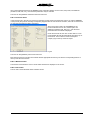
1
Complimentary Reference Material
This PDF has been made available as a complimentary service for you to assist in
evaluating this model for your testing requirements.
TMG offers a wide range of test equipment solutions, from renting short to long
term, buying refurbished and purchasing new. Financing options, such as
Financial Rental, and Leasing are also available on application.
TMG will assist if you are unsure whether this model will suit your requirements.
Call TMG if you need to organise repair and/or calibrate your unit.
If you click on the “Click-to-Call” logo below, you can all us for FREE!
TMG Corporate Website
TMG Products Website
Disclaimer:
All trademarks appearing within this PDF are trademarks of their respective owners.
Form 080/01
user manual
Transient Immunity Test Station
ECOMPACT 4
Document Title
Release date
Authors
Reference No.
ECOMPACT 4
2008-04-08
B. Straumann / C. Faust
4700220/00
Contents
1
Safety
1
1.1 General Safety information.............................................................................................................1
1.2 Safety Standards............................................................................................................................1
2
Description
2
2.1 System Overview ...........................................................................................................................2
3
Technical Data
3
3.1 Power Supply .................................................................................................................................3
3.2 Mechanical .....................................................................................................................................3
3.3 Environmental ................................................................................................................................3
3.4 EUT Monitoring ..............................................................................................................................3
3.5 System Characteristics...................................................................................................................3
3.5.1 IEC / EN 61000-4-4 Edition 2 Electrical Fast Transient Generator.......................................3
3.5.2 IEC / EN 61000-4-5 Edition 1&2 Surge Combination Wave Generator ................................4
3.5.3 IEC / EN 61000-4-11 Edition 1&2 and IEC / EN 61000-4-29 Dips and Interrupts ...............4
4
Commissioning
5
4.1 Introduction ....................................................................................................................................5
4.2 Visual Check ..................................................................................................................................5
4.3 Installing the ECOMPACT 4...........................................................................................................5
4.4 Powering the ECOMPACT 4 ..........................................................................................................5
5
Operation
7
5.1 Introduction ....................................................................................................................................7
5.1.1 Rear Panel ECOMPACT 4..................................................................................................7
5.1.2 Rear Panel EUT Supply connections ..................................................................................8
5.1.3 Front Panel ECOMPACT 4 .................................................................................................9
5.2 General Operating Instructions.......................................................................................................10
5.2.1 Select the Test Generator ...................................................................................................10
5.2.2 Adjust the Test Parameters.................................................................................................10
5.2.3 Select Output ......................................................................................................................10
5.2.4 Memory Function ................................................................................................................10
5.2.5 Fuse Function .....................................................................................................................11
5.2.6 Displayed Values ................................................................................................................11
5.2.7 Error Messages...................................................................................................................11
5.3 The EFT/Burst Generator...............................................................................................................11
5.3.1 Overview .............................................................................................................................11
5.3.2 Coupling Path and Polarity Selection ..................................................................................11
5.3.3 Displayed Values ................................................................................................................12
5.3.4 Energy Limiting ...................................................................................................................12
5.3.5 Continuous Burst.................................................................................................................13
5.3.6 Starting and Stopping the Test............................................................................................13
5.4 The Aux Function ...........................................................................................................................13
5.5 The Surge Generator .....................................................................................................................13
5.5.1 Overview .............................................................................................................................13
5.5.2 Coupling Path and Polarity Selection ..................................................................................13
5.5.3 Displayed Values ................................................................................................................14
5.5.4 Starting and Stopping the Test............................................................................................14
ECOMPACT 4
5.5.5 AC Phase Synchronization ................................................................................................. 14
5.6 The Dips / Interrupts / Variations Generator .................................................................................. 15
5.6.1 Overview............................................................................................................................. 15
5.6.2 Rear Panel Connections..................................................................................................... 15
5.6.3 Displayed Values ................................................................................................................ 15
5.6.4 Selection of Test Parameters ............................................................................................. 16
5.7 The Magnetic Field generator ........................................................................................................ 16
5.7.1 Overview............................................................................................................................. 16
5.7.2 Displayed Values ................................................................................................................ 16
5.7.3 Selection of Test Parameters ............................................................................................. 17
6
Software
18
6.1 Overview........................................................................................................................................ 18
6.2 Installation...................................................................................................................................... 18
6.3 Connection to the ECOMPACT 4 generator .................................................................................. 18
6.4 Basic terms .................................................................................................................................... 18
6.4.1 Automation file, automation window.................................................................................... 18
6.4.2 Protocol file, protocol window ............................................................................................. 19
6.4.3 Selecting the Generator...................................................................................................... 19
6.4.4 Other functions ................................................................................................................... 19
6.5 The EMV-Check screen................................................................................................................. 20
6.6 Menu Bar ....................................................................................................................................... 20
6.6.1 File Menu............................................................................................................................ 20
6.6.2 Generator menu.................................................................................................................. 20
6.6.3 Automation menu................................................................................................................ 20
6.6.4 Protocol menu .................................................................................................................... 21
6.6.5 Window menu ..................................................................................................................... 21
6.6.6 Info menu............................................................................................................................ 21
6.7 Icon Bar ......................................................................................................................................... 22
6.8 Automation window ........................................................................................................................ 22
6.8.1 Automation window icon bar ............................................................................................... 22
6.8.2 Test lines in the Automation Window.................................................................................. 23
6.9 Protocol Window ............................................................................................................................ 24
6.9.1 Protocol window icon bar .................................................................................................... 24
6.9.2 Editing text in the Protocol Window .................................................................................... 25
6.9.3 Automatic protocols ............................................................................................................ 25
7
Service
26
7.1 Maintenance .................................................................................................................................. 26
7.1.1 Cleaning ............................................................................................................................. 26
7.1.2 Fuses.................................................................................................................................. 26
7.2 Failure Diagnoses and Handling .................................................................................................... 26
7.2.1 Error Reports ...................................................................................................................... 26
7.3 Verification ..................................................................................................................................... 26
7.3.1 EFT Verification .................................................................................................................. 26
7.3.2 Surge Verification ............................................................................................................... 27
7.4 Replacement Parts ........................................................................................................................ 27
7.5 Customer Service .......................................................................................................................... 27
8
Accessories and Options
28
8.1 Accessories ................................................................................................................................... 28
8.2 Options .......................................................................................................................................... 28
ECOMPACT 4
9
Corrections and Additions
29
9.1 Addresses ......................................................................................................................................29
9.1.1 Headquarter Switzerland.....................................................................................................29
9.1.2 North America Office...........................................................................................................29
9.1.3 China Representative Office ...............................................................................................29
9.1.4 Manufacturer .......................................................................................................................29
9.2 Annex 1 to 11 .................................................................................................................................30
9.2.1 Safety circuit diagram Fig.1.................................................................................................30
9.2.2 Rear panel connections Fig.2..............................................................................................31
9.2.3 Interface to PC Fig.3 ...........................................................................................................32
9.2.4 Burst generator output Fig.4 ...............................................................................................33
9.2.5 Burst generator coupling example Fig.5..............................................................................34
9.2.6 Surge generator output Fig.6 ..............................................................................................35
9.2.7 Counter function overview Fig.7..........................................................................................36
9.2.8 Surge coupling / decoupling example Fig.8.........................................................................37
9.2.9 Internal dips transformer Fig. 9 ...........................................................................................38
9.2.10 External dips transformer Fig. 10 ........................................................................................39
9.2.11 Voltage dips and interrupts output Fig.11............................................................................40
9.3 CE Declaration of Conformity .........................................................................................................41
ECOMPACT 4
1 Safety
1.1 General Safety information
This equipment should only be operated after carefully reading the user manual.
Throughout the user manual very important or helpful advice is presented in italics.
Safety notices that must be heeded are printed in bold type
Dangerous mains voltage is present inside the Generator and at the Line Input/ Output and HV
sockets on both the front and rear panels
The power input cable must be fitted with a protective earth
For safety and functional reasons, the metallic grounding block at the rear panel needs to be
connected to a solid protection earth of your test setup
Before attempting to change fuses, remove all power cables from the instrument
Operation on supplies protected by ground fault/residual current switches is not possible
Only replace fuses with the same type and value
Before removing any covers of the instrument, remove all external connection cables
Do not open the generator, it contains no user replaceable parts. The generator should only be
maintained by trained personnel
People with heart pacemakers must not be in the vicinity of the instrument, when it is in
operation
Do not switch on or operate the instrument if an explosion hazard exists.
The system should only be operated in a dry room. If condensation is visible, dry the unit before
operating
Never touch the Equipment Under Test (EUT), when the instrument is operating. Establish a
safety barrier around the EUT to protect personnel during a test. Test cables must not be touched
during operation of the instrument.
The EUT should be covered and/or well marked during the tests.
If test objects are likely to explode during tests they must be covered with a protective cabinet
If the instrument is damaged or it is possible that damage has occurred, for example during
transportation, do not apply supply voltage
This user manual is an integral part of the test-system. Haefely Test AG and its sales partners
refuse to accept any responsibility for consequential or direct damage to persons and/or goods
due to none observance of instructions contained herein or due to incorrect use of the
instrument
1.2 Safety Standards
The ECOMPACT 4 fulfils the requirements of IEC 61010-1.
ECOMPACT 4
1
2 Description
2.1 System Overview
The ECOMPACT 4 is a compact instrument that performs common transient immunity tests such as EFT/Burst, Surge,
Line Dips and Magnetic Field according to the IEC/EN 61000-4-XX series of tests.
Fig. 2.1
2
ECOMPACT 4
3 Technical Data
3.1 Power Supply
Control Power
100, 200, 115 or 230VAC
Power Consumption
100W
Frequency
50 or 60 Hz
3.2 Mechanical
Dimensions (W x H x D)
48 x 18 x 44 cm
Weight
30 kg
3.3 Environmental
Operating Temperature
15°C - 35°C
Relative Humidity
29 – 80%, non-condensing
Atmospheric Pressure
86 – 106 kPa
Do not subject to: Direct sunlight, water, high
concentrations of dust or contaminants, shock, vibration,
abnormally high electromagnetic interference.
3.4 EUT Monitoring
Current Measurement
AC/DC up to 20A, +/-2%, +/- 2 digits
Voltage Measurement
AC/DC up to 255V, +/- 2%, +/- 2 digits
3.5 System Characteristics
3.5.1 IEC / EN 61000-4-4 Edition 2 Electrical Fast Transient Generator
Output Voltage
0.2 – 4.2 kV
Spike Frequency
0.5 – 100 kHz
Polarity
Positive and Negative
Burst Duration
0.75 – 130 ms
Output Impedance
50 Ohms
Burst Period
10 – 2400 ms
Rise Time
5 ns +/- 30%
Spikes per Second
Impulse Duration
50 ns +/- 30% (50 Ω)
50 ns –15 +100 ns (1 k Ω)
Integrated Single Phase
Coupling Decoupling
Network
Max. 2500 at U < 3 kV
Max. 1250 at U = 3 kV to 4.2 kV
33 nF coupling capacitance
1.5 mH decoupling inductance
230V AC/60V DC, 16A
Definition in accordance with IEC 61000-4-4. See Annex Fig. 4.
ECOMPACT 4
3
3.5.2 IEC / EN 61000-4-5 Edition 1&2 Surge Combination Wave Generator
Output Voltage
0.2 – 4.2 kV
Output Current
0.1 – 2.1 kA
Voltage Rise Time
Voltage Duration
1.2 us +/- 30%
Current Rise Time
8 us +/- 20%
50 us +/- 20%
Current Duration
20 us +/- 20%
Polarity
Positive and Negative
Repetition Rate
10 s – 999 s
Output Impedance
2Ω
Synchronization
0 – 359 deg, 1 deg
resolution
16.67 / 40 / 50 / 60 Hz
Integrated Single Phase
Coupling Decoupling
Network
18 uF / 0 Ω for differential mode
9 uF / 10 Ω for common mode
1.5 mH decoupling inductance
230V AC/60V DC, 16A
Definition in accordance with IEC 61000-4-5. See Annex Fig. 6.
3.5.3 IEC / EN 61000-4-11 Edition 1&2 and IEC / EN 61000-4-29 Dips and Interrupts
Max. Voltage
250V AC/DC
Interrupt Time
0.1 ms – 998 s
Max. Current
16A AC/DC
Repetition Time
0.2 ms – 999 s
Dip Levels
0%, 40%, 70%, 80%
Phase Synch.
0 – 359 degree asynchronous
16 / 40 / 50 / 60 Hz
Definition in accordance with IEC 61000-4-11. See Annex Fig. 11.
4
ECOMPACT 4
4 Commissioning
4.1 Introduction
Before using the ECOMPACT 4, please study the user’s manual carefully. Use of this equipment can be dangerous
when these instructions are not followed correctly.
Mains voltages are always a potential danger. This applies equally to all personnel. Persons with heart
pacemakers must not be in the vicinity when the ECOMPACT 4 is operating!
4.2 Visual Check
During transport, equipment can be subjected to vibration and shocks. Before operating the instrument for the first time,
check that there are no signs of mechanical damage. Heavily damaged packaging is an indication that perhaps the
instrument is damaged. Check for transport damage and immediately inform the shipping agent or your insurance
company. Claims made at a later date may not be accepted.
If damage is visible or suspected, never apply mains voltage to the instrument.
4.3 Installing the ECOMPACT 4
Place the instrument on a ground reference plane (either on the floor or on a table top) that is large and stable.
Ensure that the ventilator exit on the rear panel is not obstructed in any way. It is recommended that the equipment is
placed at least 20 cm from a wall or other obstruction.
Connect the generator GND using a copper band to the ground reference plane.
4.4 Powering the ECOMPACT 4
1. The ECOMPACT 4 may be powered from either 100, 200, 115 or 230VAC. The line voltage is preset in the factory
based on the destination of the end-user, however it may be changed at any time by removing the bottom cover of
the instrument and setting the line voltage switches as indicated in the figure below:
Fig. 4.1
Note that units supplied for use with 100V or 115V line voltage have dual 2A fuses at the line voltage input. Units
supplied for use with 230V line voltage have dual 1A fuses at the line voltage input. When changing the operating
line voltage of the instrument, the user should ensure the proper fuse rating is used based on the line voltage
selected.
ECOMPACT 4
5
2. Connect the mains power from a standard wall outlet to the LINE INPUT on the back panel of the instrument, using
the power cord supplied with the instrument.
3. Connect the EUT power supply to the COUPLING INPUT on the back panel of the instrument, using the power cord
supplied with the instrument.
Both the EUT power input sockets on the instrument and the EUT power cable supplied with the instrument are
color-coded (Black = LINE, Blue = NEUTRAL, Yellow/Green = PROTECTIVE EARTH) to ensure that the EUT
supply power is connected correctly. If the EUT supply power is connected incorrectly, the error lamp on the
back panel near the coupling input will illuminate.
4. Place the supplied safety circuit connector in the SECURITY SOCKET / EMERGENCY CUTOUT. If this connector
is not in place, the error message “EMERGENCY-STOP!” will appear on the LCD display and the unit will not
operate. Additional safety devices such as gate switches may be connected to the safety circuit connector in series.
An overview schematic of the safety circuit is provided in Annex Fig. 1.
5. Connect a suitable ground to the ground terminal on the back panel of the instrument.
6. Use the POWER switch on the front panel to apply power to the instrument. The green LED in the STBY key should
light. The LCD display will illuminate and the instrument is now ready for operation.
6
ECOMPACT 4
5 Operation
5.1 Introduction
The ECOMPACT 4 was designed for simplicity and all the functions of the instrument are controlled from the
pushbuttons and rotary control knob on the front panel. The instrument may also be operated via its RS232 interface
with the supplied “EMV-CHECK” software that can be loaded onto your PC.
Installation and operation of the “EMV-CHECK” software is described in section 6 of this operator’s manual.
5.1.1 Rear Panel ECOMPACT 4
7
8
9
13
10
12
1
3
4
5
2
11
6
Fig. 5.1
Mains input
(1)
Internally selectable 100V/115V/200V/230V, 50Hz/60Hz
Mains Input fuses
(2)
Dual fuses (5x20mm)
2A T for use with 100V or 115V line voltage
1A T for use with 200V or 230V line voltage
Communication interface
(3)
RS232 (cable included) or RS485.
See Annex Fig. 3 for more information
Safety circuit /
Emergency switch/
Warning lamp
connection
(4)
4 pole socket
Requires included security connector to enable instrument to operate. Short
circuiting pins 1+2 closes the safety circuit, and breaking the connection between
pins 1+2 signals an emergency stop.
(Emergency switch and warning lamp are not included in the standard scope of
supply)
See Annex Fig. 1 for more information
Control Output for optional (5)
external variac
SUB-D connector 9 pole female
0-10V gate voltage (10V = 127%) max. load 250 Ohms
0-20mA base current (20mA = 127%)
See Annex Fig. 10 for more information
Grounding Block
(6)
For safety and functional reasons, this terminal needs to be connected to a solid
protection earth of your test setup
Fan and cooling slots
(7)
Take care that the cooling fan and cooling slots on the rear of ECOMPACT 4 are
not obstructed.
A distance of 20cm between the equipment and obstruction is recommended
Internal dips transformer
(8)
Place the jumpers as shown when internal dips transformer is used (default)
ECOMPACT 4
7
connection
See Annex Figs. 9 and 10 for more information
External transformer
connection
(9)
An external variable transformer (optional) can be connected here.
See Annex Figs. 9 and 10 for more information
Internal coupling filter /
EUT supply connections
(10)
Connect here EUT power supply. Phase and Neutral should be connected as
indicated on the back panel
Error light
(11)
Indicates that phase & neutral connection at coupling input is interchanged
Phase Trigger /
Synch Input
(12)
Synch signal reference input when used with ECOUPLER 4
Coupling Input /
EUT supply fuse
(13)
Protects ECOMPACT 4 and EUT from overcurrent. 16A F (5x20mm)
5.1.2 Rear Panel EUT Supply connections
The coupling/decoupling network of the ECOMPACT4 cannot be used from a mains supply network protected by a
ground fault Switch (differential current switch). In such a case an isolation transformer needs to be inserted between
mains ECOMPACT4.
Fig 5.2
N’ and PE must be connected in this case, so that in the case of a failure a follow current of the mains can flow into the
EUT.
Attention:
All further equipment connected after the isolation transformer are not protected any more by the ground fault
protection switch.
The connections L', N' and PE have the same behaviour as a normal TN-S-circuit.
8
ECOMPACT 4
5.1.3 Front Panel ECOMPACT 4
12
8
3
2
5
7
16
4
6
11
13
14
15
10
9
1
Fig. 5.3
Main power switch
(1)
Activates the ECOMPACT 4
Rotary Control Knob
(2)
Adjusts test parameters and settings of the ECOMPACT 4
Display
(3)
Main visual user interface, displays all test parameters
Generator button
(4)
Used to select which generator is active
Active generator LEDs
(5)
Indicate which generator is active
Test Parameter buttons
(6)
Used to select various test parameters for adjustment
Start / Stop button
(7)
Starts and stops a selected test
Output Active
(8)
Indicates a test is in progress and voltage is present at the selected output
Generator Outputs
(9)
(10)
(11)
Line
Surge
Burst
Generator Output buttons
and indicators
(12)
Used to select and indicate the output path for the transient
Trigger output
(13)
Trigger output 5V TTL for oscilloscope triggering
Fuse button
(14)
Activates the electronic fuse function to set a mains overcurrent limit
Memory button
(15)
Used to store and recall pre-programmed tests
Ground connection
(16)
ECOMPACT 4
9
5.2 General Operating Instructions
The ECOMPACT 4 uses pushbuttons to select test parameters and a rotary knob to adjust the values. This test data is
shown on the display screen. Each pushbutton has a corresponding LED which indicates to the user which modes are
active.
5.2.1 Select the Test Generator
Press the GENERATOR button and use the rotary knob to make a selection from the following choices:
-“Surge Generator?”
-“Burst Generator?”
-“Dips / Interrupts Generator?”
-“Power Frequency Magnetic Field?”
Confirm your choice by pressing the GENERATOR button again. This should activate the LED corresponding to the
selected test. Selection of the Generator cannot be done while a test is running. Press the “Start/Stop” button to stop
the current test before making a change.
5.2.2 Adjust the Test Parameters
The following test parameters may be activated by pressing the appropriate button. NOTE that some functions are
specific to a given test and can only be activated when that generator is selected (e.g. the “Burst Time” function is
specific to the Burst test and can only be activated when the “Burst Generator” is active, and not for example when the
“Surge Generator” is active). Once activated, the corresponding LED will illuminate, and an arrow “>>” will appear in the
display next to the active parameter.
“Voltage”
“Rep Time”
“Counter”
“Phase”
Sets the output / charge voltage.
Sets the time between successive transients (also known as burst period).
Selects the number of transients generated. See Annex Fig. 7.
Selects the phase of the mains input to which the transient is synchronized.
“Frequency”
“Burst Time”
“Ramp”
“Interrupt”
Sets the spike frequency of the EFT/Burst waveform.
Sets the burst duration of the EFT/Burst waveform.
Sets the ramp time for the voltage variations test.
Sets the interrupt time for the voltage dips / interrupts / variations test.
NOTE that only one parameter / function may be activated at a time and some functions cannot be accessed while a
test is running.
5.2.3 Select Output
The ECOMPACT 4 has three transient outputs...
“Line”
“Surge”
“Burst”
The output is a European Schuko style mains connector, with six corresponding
pushbuttons and LEDs above (high and low pos
High and low
SHV
5.2.4 Memory Function
Customized tests may be stored in the memory locations of the ECOMPACT 4. Eight memory locations are provided for
Surge and Burst tests (location 0 to location 7), and four memory locations are provided for Dips/Interrupts test (location
0 to location 3).
The parameters in each memory location are factory programmed. A memory location may be overwritten at any time
with the following procedure...
Once the desired test parameters are set, press and hold the “Memory” pushbutton until the LED lights. While still
holding the “Memory” pushbutton, use the rotary knob and display to select the desired memory location number.
Release the “Memory” pushbutton. The test is now stored in the selected memory location.
To retrieve the test from memory, press and release the “Memory” pushbutton, then use the rotary knob to select the
desired memory location. Press and release the “Memory” pushbutton again and the desired test is now loaded.
10
ECOMPACT 4
NOTE that memory location #0 is the default location and the ECOMPACT 4 will load the test from location #0 each
time it is powered up or each time a new generator is selected.
5.2.5 Fuse Function
The “Fuse” pushbutton activates an electronic fuse function which allows the user to set a maximum mains current
level. If the set level is exceeded during the test, the ECOMPACT 4 will disconnect the mains voltage and display the
message “Fuse OFF” on the display. The software fuse is designed to react to sustained overcurrents (not short
duration spikes) in the same way as a fast acting mechanical fuse, but with much more precision.
For testing with DC supply voltages, the Fuse function may only be used with a maximum supply voltage of 100VDC.
When the Fuse function is used with “Dips/Interrupts” generator selected, the value should be set to the 16A default
setting. With this setting, the Fuse function is delayed by 5 seconds so as not to limit any inrush currents (as required by
the IEC 61000-4-11 standard).
5.2.6 Displayed Values
The ECOMPACT 4 uses a four line display. Lines 1 through 3 of the display show the selected test parameters. Line 4
displays (from left to right)...
The voltage “U1” at the coupling filter input
The voltage “U2” of the Dips/Interrupts generator (if selected)
The m ins frequency at the coupling filter input
For AC: 16, 40, 50 or 60Hz
For DC or no voltage applied: “asyn” (asynchronous)
Current consumption of the EUT
5.2.7 Error Messages
“Emergency Stop”
“Fuse OFF”
“Error, Overlapping”
Safety circuit is open. Connect the supplied safety circuit connector to the
“Security Circuit / Emergency Stop” socket on the back panel of the instrument.
Mains current exceeded the value set using the “Fuse” function. Adjust fuse
level or EUT as appropriate.
Conflicting test parameters were detected in the “Dips / Interrupts” generator.
The “Rep Time” must be greater than 2 x “Ramp Time” + “Interrupt Time”.
5.3 The EFT/Burst Generator
This section describes the detailed function of the ECOMPACT 4 when the “Burst Generator” is selected.
5.3.1 Overview
The Burst generator generates Electrical Fast Transient (EFT) Bursts as described in IEC 61000-4-4. The source
impedance of the generator is 50 Ohms. The burst is a common mode transient, coupled simultaneously to all selected
paths with respect to ground. The user can select between using the coaxial SHV output or the built in mains coupling
network. See also Annex Fig. 4.
5.3.2 Coupling Path and Polarity Selection
To couple the Burst waveform to a capacitive coupling clamp or external coupling filter like the ECOUPLER4 via the
SHV coaxial connector marked “Burst”, use the “Burst” pushbuttons directly above the SHV output. For positive polarity,
select the Burst “+” pushbutton, and for negative polarity select the Burst “-“ pushbutton.
To couple the Burst waveform with the built in coupling / decoupling network via the European Schuko style mains
connector marked “Line”, use the line “L”, protective earth “PE” and neutral “N” pushbuttons directly above the “line”
output. For positive polarity, select the L, PE or N “+” pushbuttons, and for negative polarity select the L, N or PE “-“
pushbuttons. Multiple lines may be selected for simultaneous coupling as required by IEC 61000-4-4. See also Annex
Fig. 5.
The polarity and coupling paths may be changed at any time before or during the test by pressing the appropriate
pushbutton.
ECOMPACT 4
11
5.3.3 Displayed Values
“V0” burst voltage (0.20 to 4.20kV)
“RE” repeat time (10ms to 2.4s)
“FR” specified frequency (0.5 to 100kHz)
“BU” burst time/duration (0.75 to 130ms)
(actual frequency in kHz) - see section on “Energy Limiting below
Voltages U1 / U2 (V)
Mains frequency (in Hz or “asyn”)
EUT current (A)
Line 1>
Line 2>
Line 3>
Line 4>
The Burst test parameters can be changed even while a test is running by pressing the appropriate pushbutton and
using the rotary control knob.
5.3.4 Energy Limiting
To protect the generator from overload, the energy output is limited. If certain limits are exceeded, the ECOMPACT 4
will automatically adjust the actual frequency based on the burst time and repeat time set by the user.
The ECOMPACT 4 is limited to approximately 500 spikes per burst (Spikes per burst = Spike Frequency * Burst Time).
The chart below shows the relationship between frequency and burst time in more detail.
130
120
110
90
100
80
70
60
50
45
40
35
30
25
20
18
16
15
14
13
12
11
9
10
8
7
6
5
4
3
1.5
100
90
80
70
60
50
40
30
20
10
0
0.75
Max. Frequency (kHz)
Frequency Limitation vs. Burst Time
Burst Time (ms)
Fig. 5.4
The ECOMPACT 4 is also limited to approximately 1250 or 2500 spikes per second depending on the set voltage:
For burst voltage from 200V to 3000V:
2500 spikes per second
For burst voltage from 3020V to 4200V: 1250 spikes per second
Spikes per second = Spikes per burst / Repeat Time = (Spike Frequency * Burst Time) / Repeat Time
So the frequency set by the user may be limited depending on the chosen burst time, voltage and repeat time.
Example 1: 5kHz burst test according to IEC 61000-4-4
Spike Frequency: 5kHz
Burst Time: 15ms
Voltage: 4kV
Repeat Time: 300ms
Spikes per burst = 5kHz * 15ms = 75.
Spikes per second = (5kHz * 15ms) / 300ms = 250
Actual Frequency: 5kHz
Limit is 500. OK!
Limit is 1250. OK!
No limitation. OK!
Example 2: 100kHz burst test according to IEC 61000-4-4
Spike Frequency: 100kHz
Burst Time: 0.75ms
Voltage: 4kV
Repeat Time: 300ms
Spikes per burst = 100kHz * 0.75ms = 75. Limit is 500. OK!
Spikes per second = (100kHz * 0.75ms) / 300ms = 250
Actual Frequency: 100kHz
Limit is 1250. OK!
No limitation. OK!
12
ECOMPACT 4
Example 3: Spikes per burst limit exceeded
Spike Frequency: 100kHz
Burst Time: 15ms
Voltage: 4kV
Repeat Time: 300ms
Spikes per burst = 100kHz * 15ms = 1500. Limit is 500. Not OK!
Actual Frequency: Limited to 30kHz (450 spikes per second)
Example 4: Spikes per second limit exceeded
Spike Frequency: 5kHz
Burst Time: 15ms
Voltage: 4kV
Repeat Time: 25ms
Spikes per burst = 5kHz * 15ms = 75.
Limit is 500. OK!
Spikes per second = (5kHz * 15ms) / 25ms = 1875
Limit is 1250. Not OK!
Actual Frequency: Limited to 2kHz (1200 spikes per second)
5.3.5 Continuous Burst
You can set the ECOMPACT 4 to generate a continuous burst by setting the Burst Time equal to (or greater than) the
Repeat Time. Maximum continuous Burst Frequency is limited based on Burst Voltage:
For burst voltage from 200V to 3000V:
For burst voltage from 3020V to 4200V:
2.5kHz
1 kHz
If these limits are exceeded, the ECOMPACT 4 will adjust the Actual Frequency as appropriate.
5.3.6 Starting and Stopping the Test
Once the test parameters are set and an output path is selected, press the “Start/Stop” button to begin the test. The
“Output Active” LED will illuminate.
If no output path is selected, the “Start/Stop” LED will illuminate, but no voltage will be generated or displayed, and the
“Output Active” LED will not illuminate. In this case, the “Output Active” LED will illuminate and the test will begin as
soon as a coupling path choice is made.
To stop the test, press the “Start/Stop” button again. The “Start/Stop”, “Output Active” and coupling path LEDs will turn
off. If the output path is changed or turned off during the test, this will not automatically stop the test. The generator will
continue to generate bursts until another coupling path is selected or until the test is stopped with the “Start/Stop”
button.
5.4 The Aux Function
This function is not currently available.
5.5 The Surge Generator
This section describes the detailed function of the ECOMPACT 4 when the “Surge Generator” is selected.
5.5.1 Overview
The Surge generator generates a standard hybrid or combination wave surge as described in IEC 61000-4-5. The
source impedance of the generator is 2 Ohms. See also Annex Fig. 6.
5.5.2 Coupling Path and Polarity Selection
The surge may be applied to the EUT directly, through an external manually operated three phase coupling filter like the
Haefely ECOUPLER4, or through the built in single phase coupling filter in the ECOMPACT 4.
To apply the surge directly to the EUT or to bring the surge to an external coupler, the dual banana jack “Surge” output
is used together with the “Surge +” or “Surge –“ pushbuttons. The surge is always coupled to the red banana jack (High)
and the black banana jack is always Common (Low). Selecting the “Surge +” pushbutton generates a positive polarity
surge from red to black. Selecting the “Surge -” pushbutton generates a negative polarity surge from red to black.
ECOMPACT 4
13
To apply the surge through the built in coupler either differentially or common mode, the
European Schuko style “Line” output is used together with the pushbuttons “L+”, “L-“,
“PE+”, “PE-“, “N+” and “N-“. The surge is always applied from the High “+” side of the
generator to the Low “-“ side of the generator, so in this way the polarity of the surge is
also controlled by the coupling path selection.
For example, pressing the “L+” and “PE-“ pushbuttons will apply a surge on the Line with
respect to Earth which appears as positive polarity when measured from L to PE, and as
negative polarity when measured from PE to L. Conversely, pressing the “PE+” and “L-“
pushbuttons will apply a surge on Earth with respect to the Line which appears as
negative polarity when measured from L to PE, and as positive polarity when measured
from PE to L. This is illustrated more clearly in the table below.
PE
L
N
PE
Fig. 5.5
Desired Coupling Path:
Line to Neutral
Line to Earth
Neutral to Earth
For Positive Polarity, press...
“L+” and “N-“
“L+” and “PE-“
“N+” and “PE-“
For Negative Polarity, press...
“L-“ and “N+”
“L-“ and “PE+”
“N-“ and “PE+”
The required coupling elements (0 or 10 Ohms, 9 or 18uF) are automatically selected by the ECOMPACT 4 depending
on the chosen coupling path.
The coupling paths may be changed at any time before or during the test by pressing the appropriate pushbutton. Only
one coupling path may be selected at a time. Simultaneous multi-line coupling is NOT possible with the ECOMPACT 4.
See also Annex Fig. 8.
5.5.3 Displayed Values
Line 1>
Line 2>
Line 3>
Line 4>
“V0” surge voltage (0.20 to 4.20kV)
“CO” impulse counter (1 to 999 surges)
Voltages U1 / U2 (V)
“RE” repeat time (10 to 999s)
“PH” phase synch (0 to 359 deg., or “---“ asyn.)
Mains frequency (in Hz or “asyn”)
EUT current (A)
The Surge test parameters may NOT be changed while a test is running.
5.5.4 Starting and Stopping the Test
Once the test parameters are set and an output path is selected, press the “Start/Stop” button to begin the test. The
“Output Active” LED will illuminate.
If no output path is selected, the “Start/Stop” LED will illuminate, but no voltage will be generated or displayed, and the
“Output Active” LED will not illuminate. In this case, the “Output Active” LED will illuminate and the test will begin as
soon as a coupling path choice is made.
To stop the test, press the “Start/Stop” button again. The “Start/Stop”, “Output Active” and coupling path LEDs will turn
off. If the output path is changed or turned off during the test, this will not automatically stop the test. The generator will
remain active and resume the test program as soon as another coupling path is selected, until the test is finally stopped
with the “Start/Stop” button.
5.5.5 AC Phase Synchronization
To superimpose or synchronize the surge onto a specific part of the AC mains supply, simply connect a suitable AC
mains supply to the Coupling Input at the rear panel of the ECOMPACT 4. Then press the “Phase” pushbutton and use
the rotary knob to select the synchronization position (0 to 359 degrees). To turn off AC Phase Synchronization, rotate
the rotary knob part 359 degrees. The display will show “---“ and Synchronization is turned off.
If no mains supply is connected to the Coupling Input at the rear panel of the instrument, the Synchronization feature
will be automatically deactivated. Likewise, the Synchronization feature will be automatically deactivated if a DC supply
is connected.
14
ECOMPACT 4
5.6 The Dips / Interrupts / Variations Generator
This section describes the detailed function of the ECOMPACT 4 when the “Dips / Interrupts Generator” is selected.
5.6.1 Overview
The Dips / Interrupts generator produces voltage dips, interrupts and variations as described in the IEC 61000-4-11 and
IEC 61000-4-29 standards. ECOMPACT 4 can handle the 500A inrush current requirement as specified by the IEC
61000-4-11 standard.
To generate Dips and Interrupts, the generator uses a VMOS switch to quickly switch between the voltage levels U1
and U2. The power supply connected to the Coupling Input on the rear panel of the instrument is considered U1. The
Dip voltage U2 is produced by a step transformer inside the generator, or by an external variac (optional).
To generate Variations, the internal step transformer is bypassed and an external variac (optional) is used. The external
variac may be manually operated, or controlled via the “Control Output” at the rear panel of the ECOMPACT 4.
Haefely model PEV1610 is a motorized external 16A variac designed specifically for use with the ECOMPACT 4. For
more information, consult your local Haefely representative.
5.6.2 Rear Panel Connections
When using the internal step transformer to produce the Dip voltage U2, the Coupling Input at the rear panel should be
connected to the Internal Transformer input using the two supplied jumpers as shown in Annex Fig. 2 “Connection setup for internal step transformer” and Annex Fig. 9 “Connection of internal Dips transformer”.
When using an external transformer such as Haefely model PEV1610 to generate the Dip voltage U2, the jumpers are
not used and instead the external variac is connected to the U1 (L, N and PE) and U2 sockets as shown in Annex fig.
10 “Connection of an external regulation transformer to the ECOMPACT 4”.
5.6.3 Displayed Values
Line 1>
Line 2>
Line 3>
Line 4>
“V0” dip voltage U2 (0 to 127% of input voltage U1)
“RE” repeat time (0 to 99.9ms / 9.99s / 999s)
“CO” event counter (1 to 999 events or “---“ continuous)
“PH” phase synch (0 to 359 deg., or “---“ asyn.)
“RA” ramp time for variations (0 to 9.99s / 999s)
“IN” interrupt time (0 to 99.9ms / 9.99s / 999s)
Voltages U1 / U2 (V)
Mains frequency (in Hz or “asyn”)
EUT current (A)
ECOMPACT 4
15
5.6.4 Selection of Test Parameters
The time parameters have multiple ranges. To toggle between ranges, press the “Repeat Time”, “Interrupt” or “Ramp”
pushbutton to highlight that parameter, then push the “Frequency” pushbutton until the desired time range is highlighted
on the display. Then use the rotary knob to adjust the value as usual.
The Repeat Time must be greater than the Interrupt Time, otherwise the error message “Error – Overlapping” will
appear on the display.
For Dips and Interrupts testing, the Ramp Time should be set to 0.
Set Counter to 0 for continuous operation
For Variations testing, the Ramp Time must be set to a reasonable value based on the variable voltage source. For
example, it is possible to set a Ramp Time of 0.05s on the ECOMPACT 4 without any error message, but this Ramp
Time is physically impossible for example for a motorized variac. If no external variable voltage source is connected, the
generator will ignore any Ramp Time setting.
While any Dip Voltage may be set on the display, the fixed Dip levels of the built in step transformer are 0%, 40%, 70%
and 80% in accordance with IEC 61000-4-11. If the user enters a Dip voltage within +/- 10% of the fixed Dip levels, the
generator will automatically use the nearest fixed Dip level. However, if the user enters a value outside this +/- 10%
range, the Dip Voltage will automatically be set to 100% (full interrupt, U2=0V).
User selected Dip Voltage on display:
0% to 30%
31% to 50%
51% to 60%
61% to 75%
76% to 90%
91% to 127%
Actual Dip Voltage used by generator:
100%
40%
100%
70%
80%
100%
The Dips / Interrupts / Variations test parameters may NOT be changed while a test is running.
5.7 The Magnetic Field generator
This section describes the detailed function of the ECOMPACT 4 when the “Power Frequency Magnetic Field
Generator” is selected.
5.7.1 Overview
The Magnetic Field generator is used together with the 1m x 1m model MFS100 magnetic field coil to produce power
frequency magnetic fields for immunity testing as described in the IEC 61000-4-8 standard.
In this mode, the generator uses the dip voltage U2 set by the user to drive the magnetic field coil. The user adjusts the
“Interrupt Time” to set the total ON time for the test.
5.7.2 Displayed Values
Line 1>
Line 2>
Line 3>
Line 4>
16
“V0” output voltage U2 (0 to 127% of input voltage U1)
“RE” repeat time (0 to 99.9ms / 9.99s / 999s)
“CO” event counter (1 to 999 events or “---“ continuous)
“PH” phase synch (0 to 359 deg., or “---“ asyn.)
“RA” ramp time for variations (0 to 9.99s / 999s)
“IN” interrupt time (0 to 99.9ms / 9.99s / 999s)
PFM / U2 (V)
Mains frequency (in Hz or “asyn”)
EUT current (A)
ECOMPACT 4
5.7.3 Selection of Test Parameters
The time parameters have multiple ranges. To toggle between ranges, press the “Repeat Time”, “Interrupt” or “Ramp”
pushbutton to highlight that parameter, then push the “Frequency” pushbutton until the desired time range is highlighted
on the display. Then use the rotary knob to adjust the value as usual.
The Repeat Time must be greater than the Interrupt Time, otherwise the error message “Error – Overlapping” will
appear on the display.
Set Counter to 0 for continuous operation
For Variations testing, the Ramp Time must be set to a reasonable value based on the variable voltage source. For
example, it is possible to set a Ramp Time of 0.05s on the ECOMPACT 4 without any error message, but this Ramp
Time is physically impossible for example for a motorized variac. If no external variable voltage source is connected, the
generator will ignore any Ramp Time setting.
While any Dip Voltage may be set on the display, the fixed Dip levels of the built in step transformer are 0%, 40%, 70%
and 80% in accordance with IEC 61000-4-11. If the user enters a Dip voltage within +/- 10% of the fixed Dip levels, the
generator will automatically use the nearest fixed Dip level. However, if the user enters a value outside this +/- 10%
range, the Dip Voltage will automatically be set to 100% (full interrupt, U2=0V).
User selected Dip Voltage on display:
0% to 30%
31% to 50%
51% to 60%
61% to 75%
76% to 90%
91% to 127%
Actual Dip Voltage used by generator:
100%
40%
100%
70%
80%
100%
The Dips / Interrupts / Variations test parameters may NOT be changed while a test is running.
ECOMPACT 4
17
6 Software
6.1 Overview
The EMV-Check software package included with the ECOMPACT 4 allows the user to control the ECOMPACT 4 and
ECOUPLER4 from a PC and create basic automated routines and test reports. The software is supplied on diskette and
is compatible with all Windows 9X/00 versions.
Automated tasks and routines are constructed using command lines that are executed sequentially by the generator.
The generator can also be operated manually during these routines which allows the user to choose between the
convenience of full automation, and the flexibility of semi-automatic operation. The user can also incorporate simple text
displays with instructions or messages to prompt the operator and speed along the test process.
Test reporting / data logging is performed independently from the task automation, and can even be done if the
generator is being operated manually. Once the generator is started, all results and modifications will be registered in
the protocol along with their time of occurrence. The operator can choose which test parameters are included in the
protocol and can insert comments at any time, allowing for user-customization of the test report. Protocol files are saved
in a *.RTF format to allow further modification by the user with MSWord or other test editors.
6.2 Installation
To install the EMC-Check software, insert the
floppy disk into the drive and start the installation
program SETUP.EXE.
After the installation, you can run the “Choose
Language” program to select either English or
German as the primary language. Once a selection
is made, this becomes the default language for the
EMV-Check software.
Fig. 6.1
6.3 Connection to the ECOMPACT 4 generator
Use the supplied cable to connect the interface port at the rear panel of the ECOMPACT 4 to the serial port of your PC.
The standard configuration is RS232, however the more noise resistant RS485 interface is available with an optional
interface converter.
6.4 Basic terms
6.4.1 Automation file, automation window
The automation file contains all the data for the automated task control. Each data record in this file is referred to as a
“line”. These data lines are viewed in the automation window. Automation files can be named and saved by the user,
but the file extension is selected automatically by the EMV-Check software as follows:
Burst Generator tests:
Surge Generator tests:
Dips / Interrupts tests:
18
ECOMPACT 4
*.FBN and *.TBN
*.FHY and *.THY
*.FNU and *.TNU
6.4.2 Protocol file, protocol window
The protocol lines from the test in progress are stored in a protocol file and displayed in protocol window. The protocol
file can be named and saved by the user, and the file extension *.RTF rich text format is automatically selected by the
EMV-Check software. The size of the protocol file is limited, so if the limit is exceeded the EMV-Check software will
create multiple protocol files with a one digit extension (e.g. protocol1.rtf, protocol2.rtf, protocol3.rtf, etc.).
Fig 6.2: The protocol window
6.4.3 Selecting the Generator
The ECOMPACT 4 allows the user to select between the EFT/Burst generator, the Surge generator, the Dips/Interrupts
generator, and the Magnetic Field generator. In the EMV-Check software, these generators are referred to by a threeletter code, as follows:
Burst Generator:
Surge Generator:
Dips / Interrupts and
Magnetic Field Generators:
BNG
HYG
NUG
Selection of the active generator is made by clicking the appropriate button in the EMV-Check software toolbar:
Fig. 6.3
6.4.4 Other functions
Start starts the first line of the automation file as displayed in the automation window.
Pause stops the execution of the automation file as soon as the line in process has reached its end. Once the execution
stops, the user can cancel the automation entirely or restart the automation at any line desired.
Single Step executes the active line only. The active line is marked in the automation window. After execution of the
active line the system will be set to pause mode.
Stop causes an immediate stop of the automation. After a stop, the user must start the automation again beginning at
the first line. The automation may also be stopped and started at any time using the START/STOP button on the
ECOMPACT 4 generator.
Go to starts the automation from the active line and continues to the end of the automation.
ECOMPACT 4
19
6.5 The EMV-Check screen
Fig 6.4
1.) Menu bar
2.) Icon bar
3.) Automation window, icon bar
4.) Automation window, data records
5.) Automation window, stop text
6.) Automation window, protocol text
7.) Protocol window, icon bar
8.) Protocol window, editor
6.6 Menu Bar
Fig 6.5
6.6.1 File Menu
In the File menu, the user can start a new test routine, save automation and protocol files, and load previously saved
automation and protocol files. The user can also insert all the lines from a previously saved automation file into the
current application directly after/behind the active line.
The printer setup function is also in the File menu.
6.6.2 Generator menu
In the Generator menu, the user selects the active generator – Burst, Surge or Voltage Interruptions. When using the
ECOMPACT 4, Combi should always be selected as opposed to Single. The generator may also be selected with the
function keys F6, F7, F8, or with the BNG, HYG and NUG buttons on the menu bar.
Reset returns the selected generator to its default condition.
6.6.3 Automation menu
In this menu, the user can start, pause and stop a test, or move by a single step through the automation protocol.
These functions are also available by using the assigned function keys or with the corresponding buttons at the top of
the automation window.
20
ECOMPACT 4
Also in the Automation Menu are the options for the Automation Window such as color, beep on/off, text attributes
(underline, bold, italic, etc.), and which test parameters may be selected.
The user can also print the automation lines from this menu.
6.6.4 Protocol menu
In the Protocol menu, the user can use the on command to start and stop recording the protocol, or insert a comment
in the protocol (the protocol recording is temporarily stopped when the user enters a comment, and must be turned back
on when the user finishes entering comments).
Also in the Protocol menu are the options for the
Protocol Window such as color, button styles, text
attributes (underline, bold, italic, etc.), and which test
parameters are recorded and displayed.
Under the Protocol tab, the user can also select a *.RTF
format header file that will automatically print at the top of
the Protocol. This is useful to insert for example a
company logo at the top of the test report.
Fig 6.6
The user can also print the protocol from this menu.
Most of these functions can also be accessed with the appropriate function keys or with the corresponding buttons at
the top of the Protocol Window.
6.6.5 Window menu
The Window menu allows the user to choose which windows are displayed on the screen.
6.6.6 Info menu
The Info menu shows the EMV-Check software version.
ECOMPACT 4
21
6.7 Icon Bar
Fig 6.7
Icons for the more common functions are displayed on the Icon Bar in three groups. From left to right, these are:
Automation file commands:
Load automation file
Save automation file
Insert automation file behind active line
Automation window on/off
Raise automation window to front
Protocol file commands:
Load protocol file
Save protocol file
Protocol window on/off
Raise protocol window to front
Generator controls:
BNG select burst generator
HYG select surge generator
NUG select Dips/Interrupts generator
Restart generator
The light bulb icon at the far right indicates the status of the serial connection to the generator. Green signals a good
serial connection, red indicates a communication failure. An unlit bulb shows there is no communication activity (e.g.
after the test stops).
6.8 Automation window
Fig. 6.8: The automation window
6.8.1 Automation window icon bar
Fig 6.9
Icons for the more common Automation Window functions are displayed at the top of the Automation Window in four
groups.
The first group is automation control icons. These are used to control the progress of the test, and they are from left to
right:
Start
Pause
Single step
Stop
Go to / skip
The next group are functions for creating and editing automation control lines:
Undo
22
ECOMPACT 4
Cut
Copy
Paste
Delete
Insert line
Copy active line
The remaining icons are:
Text display on/off
Print file
“Line” shows the active line number corresponding to the numbered test lines in the Automation Protocol. Clicking on
the “Line” icon allows the user to jump to a specific line number if desired.
The last icon is either “T. Time” (elapsed test time) or “Counter” (number of events remaining) depending on which
generator is selected.
6.8.2 Test lines in the Automation Window
Each test line in the Automation window contains the commands for a single automation cycle for the generator
selected. Test lines are numbered on the far right hand side of the window and are executed sequentially by the EMVCheck software.
Before an operation can be carried out on a given test line (or lines), it must first be selected as active. To select an
active line, move the mouse cursor to the leftmost part of the desired line. The cursor will change to a “+” sign. Clicking
the mouse selects the entire line and the line now appears highlighted. To unmark a line, repeat this procedure. To
mark more than one line, repeat this procedure for each line individually.
Fig 6.10
Test lines are divided into three sections. In the left section, the user selects the output characteristics of the generator
such as coupling path and polarity for the EFT and surge generators, and ramp characteristics for the Dips/Interrupts
generator. The software checkboxes are the same as the pushbuttons on the ECOMPACT 4 instrument and are used in
the same way. If the user makes an incorrect selection, the EMV-Check software will automatically correct it.
In the middle section, the user has the following options:
“Man” indicates manual operation of the ECOMPACT 4 generator. When this is selected, the generator is controlled
from the front panel of the instrument and cannot be controlled from the software. If “Man” is not selected, the
generator can be controlled only from the software. However, for safety reasons, the “Start/Stop” button on the
ECOMPACT 4 front panel are always active, even when the unit is software-controlled.
“Val” sends the values in the Test Line to the generator before starting the test. If the “Val” button is not selected, the
test will be run with the default generator settings. This feature is included to prevent the software from overwriting
particular settings that the user may have already programmed manually into the ECOMPACT 4.
When “Strt” is selected, the software will automatically run the test line when the automation routine is run. If “Strt” is
not selected, the automation routine will wait for the user to press the “Start/Stop” button on the front panel of the
ECOMPACT 4.
When the “StpT” StopText button is selected, the software will display a message that must be acknowledged by the
user before the test will begin. The user can enter the desired StopText message in the “StpT” field at the bottom of
the Automation Window.
When the “ProT” ProtocolText button is selected, the software will insert a user-defined message into the test
protocol in the Protocol Window. The user can enter the desired ProtocolText message in the “ProT” field at the
bottom of the Automation Window. This is useful for inserting a text message in the final test report that describes the
ECOMPACT 4
23
test line being run. With the “ProT” button deactivated, the user can also use the “ProT” ProtocolText field to insert
comments while the test is running.
In the right section of the Test Line, the user selects the test parameters for the generator such as voltage, event time,
phase, etc. When a parameter is selected, a pop-up window appears and the user can either manually type in the
desired value or adjust the slidebar control with the mouse or arrow keys. Click OK to confirm the entry, or Next to
adjust the value on the next Test Line. In some cases (eg. when setting time parameters on the Dips/Interrupts
generator) a second vertical slidebar will appear. This slidebar controls the time scale (eg. 0.0ms, 0.00s, 00.0s).
When using the ECOMPACT 4 together with the ECOUPLER4 three phase coupling network, activate the “CFG”
button to turn on three phase coupling options. The ECOUPLER4 is manually operated, so the EMV-Check software will
not automatically change coupling paths, but it will adjust the test protocol so the correct three phase test results are
shown.
6.9 Protocol Window
Fig 6.11
6.9.1 Protocol window icon bar
Fig 6.12
Icons for the more common Protocol Window functions are displayed at the top of the Protocol Window in four groups.
The first and groups are text format icons.
Bold
Italic
Underline
Strikethrough
Set color for warning text
Set color for informational text
Set color for test results text
The next group are functions for creating and editing lines in the protocol:
Undo
Cut
Copy
Paste
Delete
The remaining icons are:
Print file
Protocol on/off
24
ECOMPACT 4
6.9.2 Editing text in the Protocol Window
When the Protocol is turned off, it is no longer recording test events and the user can then edit text in the Protocol
Window just like any other word processing program. The Protocol File is saved in the *.RTF rich text format, so it may
also be exported and edited in other programs like MSWord or WordPerfect.
6.9.3 Automatic protocols
The EMV-Check software will automatically insert certain data into the protocol such as time, date, and generator data.
It will also automatically insert certain error and status messages like “No Connection”, “Emergency-Off”, “Stop”, etc.
ECOMPACT 4
25
7 Service
7.1 Maintenance
7.1.1 Cleaning
Remove the mains and all other cables from the instrument. The front panel, case and rear panel can be cleaned
with a damp, lightly soaped cloth.
7.1.2 Fuses
This instrument has two 1A or 2A fuses at the mains power input and a 16A fuse at the power input of the coupling
network on the rear panel of the instrument. Be sure to disconnect mains power from the instrument before changing
the fuses.
7.2 Failure Diagnoses and Handling
7.2.1 Error Reports
Error Report
Description / Action
“Emergency Stop”
Safety circuit is open. Ensure safety circuit plug is fitted to
the security socket on the rear panel. Ensure all additional
switches connected to the safety circuit (gate switch, etc.)
are closed.
“Fuse Off”
Measured EUT current exceeded the user selected fuse
value. The software fuse can be rest by pressing the
FUSE button. To extend the life of the disconnect relay, it
is recommended that any short circuit be cleared before
resetting the fuse.
“Error, Overlapping”
Certain test parameters conflict. For example, during Dips
/ Interrupts testing, the Rep Time must be greater than the
Interrupt Time.
7.3 Verification
In addition to the calibration service offered by your Haefely Test Service center, it is also possible to verify the
generator outputs at the user site.
7.3.1 EFT Verification
The Haefely EFT Verification Kit includes a 50 Ohm and 1000 Ohm attenuator as
required by the IEC 61000-4-4 standard. The appropriate attenuator is fitted to the
“Burst” coaxial output, and an oscilloscope is then connected to the output of the
attenuator. For measuring the waveform at the output of the coupling filter, single
phase and three phase adapters are available. For more information on the EFT
Verification Kit, consult your local Haefely representative.
NOTE: Be sure to disconnect mains power from the Coupling Input before connecting
the measuring attenuators. Measuring attenuators are designed for burst voltages
only and will be destroyed if subjected to AC/DC voltage.
Fig. 7.1
26
ECOMPACT 4
7.3.2 Surge Verification
The Haefely PDP8000 is a differential impulse measurement probe that
can be used to measure surge pulses instead of the cumbersome
traditional method of aligning dual probes. Two banana plug cables are
provided as the High and Common inputs to the PDP8000, and a
coaxial output is provided for connection to an oscilloscope. The divider
ratio is 1000:1 and the PDP8000 is rated up to 8kV for surge, 690VAC
or 400VDC. For more information on the PDP8000, consult your local
Haefely representative.
Fig. 7.2
7.4 Replacement Parts
Please consult your local Haefely sales or service representative.
7.5 Customer Service
Please feel free to contact your local Haefely representative for any of the following needs:
•
•
•
•
•
•
New product information
Accessories
Replacement parts
Technical questions
Equipment calibration
Equipment repair
Haefely has three sales and service locations, plus dozens of local representatives throughout Europe, Asia and North
America.
For the most up to date list of sales representatives, please consult our website at www.haefelyEMC.com.
ECOMPACT 4
27
8 Accessories and Options
8.1 Accessories
The ECOMPACT 4 is delivered with the following standard accessories:
1
1
1
1
1
2
10
1
1
User manual
Safety circuit connector
Equipment mains cable 10A
EUT supply mains cable 16A
RS232 communication cable
Internal dips transformer jumpers
Spare fuses 16A F for EUT supply
EMV-Check software diskette
Test certificate
8.2 Options
Description
Ordering No
ECOUPLER 4 3 phase external coupling / decoupling
network, 16A/440V AC.
249101
MFS 100 Magnetic field set according to IEC 61000-4-8 up
to 100A/m and IEC 61000-4-9 up to 1000A/m
249102
PEV 1610 motorized external variac 16A single phase
For IEC 61000-4-11 edition 1 compliance testing and
IEC 61000-4-11 edition 2 precompliance testing
249103
PESD 1610 ESD gun up to 16.5kV
249962
IP4A capacitive coupling clamp
249130
PCD 121 data line coupling network symmetrical
249801
PCD 126A data line coupling network asymmetrical
249803
EFT VERIFICATION SET
249995
EFT VERIFICATION ADAPTER for ECOMPACT 4 (single
phase)
249104
28
ECOMPACT 4
9 Corrections and Additions
9.1 Addresses
9.1.1 Headquarter Switzerland
e-Mail:
[email protected]
Address:
Haefely Test AG
Haefely EMC Division
Lehenmattstrasse 353
CH-4052 Basel / Switzerland
Telephone :
Fax :
+ 41.61.373 41 11
+ 41.61.373 49 12
Internet:
www.haefelyEMC.com
9.1.2 North America Office
e-Mail:
[email protected]
Address:
Hipotronics Inc.
Haefely EMC Division
1650 Route 22
Brewster, NY 10509 / USA
Telephone :
Fax :
+1 845 279 3644 x262
+1 845 279 2467
Internet:
www.haefelyEMC.com
9.1.3 China Representative Office
e-Mail:
[email protected]
Address:
Haefely Test AG Representative Office
8-1-602, Fortune Street
No.67, Chaoyang Road, Chaoyang District
Beijing 100025
Peoples Republic of China
Telephone :
Fax :
++86 10 8578 8099/8199/8299
++86 10 8578 9908
Internet:
www.haefelyEMC.com
9.1.4 Manufacturer
e-Mail:
[email protected]
Address:
Haefely Test AG
Haefely EMC Division
Lehenmattstrasse 353
CH-4052 Basel / Switzerland
Telephone :
Fax :
+ 41.61.373 41 11
+ 41.61.373 49 12
Internet:
www.haefelyEMC.com
ECOMPACT 4
29
9.2 Annex 1 to 11
9.2.1 Safety circuit diagram Fig.1
30
ECOMPACT 4
9.2.2 Rear panel connections Fig.2
ECOMPACT 4
31
9.2.3 Interface to PC Fig.3
32
ECOMPACT 4
9.2.4 Burst generator output Fig.4
ECOMPACT 4
33
9.2.5 Burst generator coupling example Fig.5
34
ECOMPACT 4
9.2.6 Surge generator output Fig.6
ECOMPACT 4
35
9.2.7 Counter function overview Fig.7
36
ECOMPACT 4
9.2.8 Surge coupling / decoupling example Fig.8
ECOMPACT 4
37
9.2.9 Internal dips transformer Fig. 9
38
ECOMPACT 4
9.2.10 External dips transformer Fig. 10
ECOMPACT 4
39
9.2.11 Voltage dips and interrupts output Fig.11
40
ECOMPACT 4
9.3 CE Declaration of Conformity
DECLARATION OF CONFORMITY
Haefely Test AG
Lehenmattstrasse 353
4052 Basel
Switzerland
declare, under his own responsibility, that the product here mentioned, complies with the
requirements of the listed standards or other normative documents.
So, the product complies with the requirements of the EMC directive 89/336/EEC,
92/31/EEC and 93/68/EEC and the low voltage directive 73/23/EEC and 93/68/EEC.
Product:
ECOMPACT 4
Description:
The product ECOMPACT 4 generates electromagnetic interference according
to different IEC standards. It is used to verify the conducted immunity of
electrical products.
Standards:
EN 61326: 1997 +A1:1998 +A2:2001 +A3:2003
EN 61010-1: 2001
L. Walder
Director Product Development
Haefely Test AG
Basel / Switzerland
Basel, November 4, 2005
Important Notice:
The function of this equipment is to generate electrical interference. Because of this the limits
defined for emission can be exceeded for short periods when the high voltage is switched on.
Haefely Test AG, Lehenmattstrasse 353, CH-4052 Basel / Switzerland
Phone +41.61.373 41 11, Fax +41.61.373 49 12, www.haefelyEMC.com, e-Mail: [email protected]
ECOMPACT 4
41