1
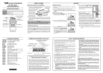
3 ʬFunction Instruction
1R
Panel
Display
Function Name
1
POWER Power indicator
2
TIMING
3
CW
4
CCW
5
H.F
6
C/S
7
TIM
8
+V/-V
Power input terminal
9
A/B/
C/D/E
Motor wiring
10
1P/2P
pulse input mode
Excitation timing
output indicator
Instruction
LED lamp shines upon
power input
LED lamp shines one time
upon operating 0.72°/step
2PULSE :Input CW signal
1PULSE :Input running Pulse
2PULSE : Input CCW signal
Counterclockwise
1PULSE : Input direction pulse
When signal inputs, the motor
Relieve motor retentivity
does not excite.
2 kinds of micro division No signal: M1 Selection
Signal inputs:M2 Selection
selection input
When rotating 0.72°/step, a
Excitation release output
signal output.
Clockwise
11
OFF/ACD Auto current cutback
12
TEST
Self-inspection switch
13
RUN
Adjust motor running
current
14
STOP
Adjust motor stopping
current
15
M1
First micro division
selection
16
M2
Second micro division
selection
DC 24V input
Please refer to No. 8
-motor wiring
1P side , 1 pulse input mode
2P side , 2 pulse input mode
After stopping input pulse about 0.2
seconds, Motor current will
automatically cutback
The driver will rotates (CW)
at the speed of 1pps
Please refer to No.5-Adjust
motor running current
Please refer to No.5-Adjust
motor current cutback rate
Please refer to No. 6-Adjust
micro division
Please refer to No. 6-Adjust
micro division
5