1
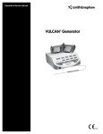
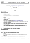
User Manual
C-Trak Galaxy
®
Gamma Probe System
www.southernscientific.co.uk
Contents
1.0 Introduction
3
8.0 Use of Optional Accessories 22
1.1 C-Trak® Analyzer and Probe Introduction 3
8.1 C-Trak® Galaxy System Cart 22
1.2 C-Trak Getting Started Guide 3
8.2 Printer
22
1.3 C-Trak® Quick Reference for Surgical Use 4
8.3 Lechner Collimator 22
8.4 Indium Shield Assembly 22
®
2.0 Getting acquainted with the C-Trak® System
5
2.1 Front Panel
5
2.2 Bottom Panel
6
2.3 Right Panel
6
2.4 Accessing the Display Screens (Sections 1-14)
7 - 16
9.0 International Symbols
Appendix A
Warranty, Receiving Examination, Returns and Repairs 3.0 Calibration Guidelines
17
Appendix B
3.1 Isotope Check Source (Sections 1-2)
17
Troubleshooting FAQ 3.2 Check Source Holder Use
17
3.3 Performing Calibration (Systems Test)
17
4.0 Pre-Surgery Set Up
18
4.1 Before Power Is Turned On
18
4.2 Background Test
18
Error Messages EMC Precautions 5.1 Use of Sheath
18
Proof of Cleaning Statement 5.2 Disinfecting
18
5.3 Decontamination
5.4 Sterilization
6.0 Safety Considerations
20
6.1 Error Messages 20
6.2 Power Supply Requirements
20
6.3 Disassembly
20
6.4 Radioactive Concerns
20
6.5 Use of Electrosurgical Devices
20
6.6 Use of Accessory Equipment
20
6.7 Probe Handling Guidelines
20
7.0 Technical Specifications
21
7.1 Power / Probe Overload Cutoff 21
7.2 LCD Display
21
7.3 Probe Cable Connector
21
7.4 Size 21
7.5 Weight 21
7.6 Finish
21
7.7 Mode of Operation 21
7.8 Serial Numbers 21
7.9 Environmental Limits
21
7.10 Label Legibility
21
2
www.southernscientific.co.uk
25
26
Appendix D
Appendix E
19
24
Appendix C
5.0 Sterile Practicies, Cleaning, and Disinfecting 18
18 - 19
23
27
28
Appendix F
Care Wise Products List, Instructions
for Detaching C-Trak® Cable 29 - 30
Appendix G
Manufacturer’s Radioactive Material
Exempt Quantity Statement 30
Probe Handling Information
31
Care Wise contact information:
Europe, United Kingdom and Rest of World:
Southern Scientific, Ltd.
Scientific House, The Henfield Business Park
Shoreham Road, Henfield, West Sussex
BN5 9SL, United Kingdom
Tel: +44 (0)1273 497600
Fax: +44 (0)1273 497626
Web: www.southernscientific.co.uk
United States:
Care Wise c/o LabLogic Systems Inc.,
1040 East Brandon Boulevard,
Brandon, Florida, 33511-5509 USA
Tel: US (813) 626-6848
Fax: US (813) 620-3708
Web: www.carewise.com
1.0 Introduction
1.1 C-Trak® Analyzer and Probe Introduction
1.2 C-Trak® Getting Started Guide
The C-Trak® Galaxy system has been designed to detect and
quantify the nuclear radiation from gamma emitting isotopes
ranging in energy emissions between 27-600 keV. A clear display
of numeric quantities and an audible signal convey an increase
or decrease in radiation detection allowing the surgeon to
localize radiolabeled tissue for excision.
(1) Attach the Monitor to the Stand. Place the stand on a flat,
stable surface. Slide computer onto stand carefully until
the ‘Quick Release’ bracket on the back of the computer
locks into the bracket on the stand. Alternatively, if using
an accessory cart, slide computer onto the bracket
mounted on the cart.
The system is comprised of the C-Trak® Galaxy touchscreen
analyzer and one or more of the OmniProbe® family of probes.
The OmniProbe® and OmniProbe®-EL are capable of detecting
gamma ray energies up to 364 keV. The OmniProbe®-PET is capable
of detecting gamma ray energies up to 600 keV. The analyzer is
designed for operation with Care Wise designed gamma probes.
(2) Connect the Care Wise provided Power Cord. Check that
the power supply cables are free of any nicks, cuts, exposed
wires or other damage. Connect the power supply to the
computer and to an AC outlet. Turn on the power supply
with the switch on the back of the power supply. An indicator
light on top of the power supply should glow.
C-Trak® probes have special collimation and shielding that allow
highly directional detection of radiation from sites of interest,
along with greatly reduced detection of background radiation.
(3) Connect the Probe. Check that probe cable is free of any nicks,
cuts, exposed wires or damaged connectors. Connect the
probe to the monitor and then turn the power on using the
power button on the front of the monitor. [Reminder:
The OmniProbe® is a Type B Applied Part .]
The analyzer is designed to operate the probe, display the data
from the detected radiation, and display and control the system’s
operating parameters. The result is optimum performance in
measuring gamma radiation from the photopeak of isotopes
such as Technetium-99m (Tc99m), Indium-111 (In111),
Iodine-125 (I125) and Fluorine-18 (18F-FDG) while
minimizing detection of Compton-scattered radiation.
The C-Trak® Galaxy system meets IEC 60601-1 3rd Edition medical
safety testing and certification requirements. Its comprehensive
shielding of high voltage sites within the instrument eliminates
the possibility of significant electrical current leakage to patient
or user under normal operating conditions. The C-Trak® Galaxy
system has excellent electrical safety; the system is designed to
turn off the high voltage if the current exceeds 10 µA, or if any
short circuit is detected. The system has been designed and
manufactured for safe operation in an operating room
environment, as long as flammable anesthetic gases are
not used and the system is not physically abused.
The C-Trak® Galaxy CW4000 System is CE
certified and is fully compliant with FDA
(21 CFR Part 820), MDD (93/42/EEC)
and CMDR (SOR/98-282) requirements.
The C-Trak® Galaxy system takes a few minutes to start up
(boot) completely. Once the system displays the Count Screen,
(described in section 2.4-1), it is ready for use.
NOTE: To verify or reset the clock time if the system has been
relocated, press ‘Main Menu’, then ‘Setup’, then ‘Select Time
Zone’ to choose the time zone for your area.
(1) Attach Monitor to Bracket
0843
Slide computer monitor
quick release bracket over
stand bracket until the tab
locks into place.
Monitor Bracket
Stand Bracket
(2) Connect Power Cord
(3) Connect Probe
Assembly of the C-Trak® Galaxy System
3
C-Trak Galaxy Gamma Probe System
1.3 C-Trak® Quick Reference for Surgical Use
1.
Ensure that the Galaxy Analyzer is securely attached to
the stand. Check that the power cable and probe cable
are free of any nicks, cuts, exposed wires or damaged
connectors. Ensure that the power box is on. Connect
probe, and then turn the Galaxy power on,
as in steps 1-3 above.
2. Ensure that:
a. The probe connected to the analyzer is the
probe listed on the Count Screen [Fig. 4].
b. The Isotope shown on the Count Screen
is the isotope that will be used.
3. Set RANGE at desired setting based on the expected
level of activity. A range of 0-100 is often preferred
for the initial survey [Figure 1].
4. Check VOLUME setting to ensure a comfortable level [Figure 1].
5. Take background test [Section 4.2] to ensure
probe is free of contamination.
6. Use the probe to locate the area of greatest radiation
uptake of clinical interest before making the first incision.
7.
In sentinel node procedures, always remain conscious of
the location of the injection site in order to differentiate
between very high levels of radiation coming from the
injection site and radiation coming from the desired tissue;
e.g., sentinel lymph node itself. It can be helpful to mark
the patient’s skin to show the boundary of the very high
level radiation coming from tissue immediately
surrounding the injection site.
8. Move the probe slowly and avoid jerky movements.
With experience the user will develop a ‘feel’ for
the appropriate speed.
9.
Detected count rates drop with the square of the distance
from tissue being viewed. Stay very close to the tissue plane.
While performing the initial survey, be careful not to push
the probe into the skin while moving it, as this will also
move the skin relative to the lymphatics.
10.When the tissue of interest has been excised, take a
10-second count for the ex vivo specimen(s) and for
the cavity (background). This will establish whether
all significantly radioactive tissue has been removed.
The 5µCi Co-57 check source should be replaced every
18-24 months. Na-22 check source should be replaced
every 5 years. Check sources may be purchased through
Care Wise or your Care Wise distributor. See Product List,
Appendix F, for Product Codes.
Call Care Wise on +1-813-626-6848 (US & Canada)
+44 1273 497600 (Europe & Worldwide) with any inquiry.
4
www.southernscientific.co.uk
C-Trak® Galaxy Count Screen
2.0 Getting acquainted with the C-Trak® System
2.1 Front Panel [Figure 1]
(1) Display Screens – Depending on the specific screen selected,
displays the data on radiation detected by the system, the
specific configuration of the system when in use, or the
information needed to calibrate or reconfigure
the system as desired.
(2) Brightness Controls – Adjust the brightness
of the system’s display screen.
(3) Power Switch – Turns the system on. To shut down
the system, navigate to the Main Menu and
select ‘Shutdown.’
(4) Volume Controls – Adjust the system volume.
(1) Display Screen
(4) Volume Controls
(2) Brightness Controls
(3) Power Switch
Figure 1 – Front Panel of C-Trak® Galaxy System
5
C-Trak Galaxy Gamma Probe System
2.0 Getting acquainted with the C-Trak® System (continued)
2.2 Bottom Panel [Figure 2]
(1) Power – DC In Connection
• External, Universal AC input (100-240 vac 47-63 Hz),
100 watts, DC-out: 12 V.
• For U.S. applications, the AC mains plug
is Hospital Grade, NEMA 5-15P-HG.
• Contact Care Wise or your Care Wise distributor
to supply or replace the proper AC mains
plug/cable for your application.
(2) USB Connectors – These are ONLY for use with Care Wise
approved peripherals (e.g. Care Wise approved accessory
printer [Section 8.2]). Attaching any devices not explicitly
approved by Care Wise (including keyboards, mice, other
printers, etc.) can lead to loss of functionality and system
damage. DO NOT PLUG ANY UNAPPROVED DEVICES
INTO THE C-TRAK® GALAXY SYSTEM!
(2) USB Connectors
(1) Power Cable Connection
Figure 2 – Bottom Panel of C-Trak® Galaxy System
2.3 Right panel [Figure 3]
Probe Connector – The analyzer connection is a MHV style
high-voltage connector for all Care Wise probes.
(NOTE: This is not a “BNC” connector.)
Probe
Reminder: The OmniProbe®
is a Type B Applied Part
Figure 3. – Right Panel of C-Trak® Galaxy System
6
www.southernscientific.co.uk
2.4 Accessing the screens
The C-Trak® Galaxy is a touchscreen system. To change screens or
input data, select the desired field by touching the corresponding
‘button’ with your finger. The screen will respond to bare or gloved
fingers or other stylus and solid instruments. Please use caution when
using anything other than your finger. The screen can be damaged.
You may wish to use a clear plastic ‘screen protector’ product.
Note: ‘Grayed out’ buttons indicate options that
are unavailable based on current settings.
Note: There may be differences in the screen on your
analyzer from those presented here due to revisions
to the system software over time.
2.4-1 Count Screen
The first screen to appear when the system starts up is the Count
Screen, which displays feedback about the amount of radiation the
probe detects [Figure 4]. The features of this screen are described
below. Refer to Figure 4 and the numeric reference for details.
(1) Rate Meter Display
• There are three versions of the RATE METER DISPLAY. The
default, shown in Figure 4, uses a wedge-shaped indicator
to show the amount of radiation detected. The other two
versions of the RATE METER DISPLAY are an analog
indicator and a histogram of counts per second over
time. These are shown in Figures 5 and 6 respectively.
• *NOTE: To change the version of meter being used,
touch any free space, or touch on the meter itself.
(2) Counts per Second Display – This numerical display
indicates the number of photons detected by the
gamma probe per second.
(3) Range Controllers – The DECREASE RANGE and INCREASE
RANGE controllers are used to adjust the range of counts
per second displayed. Ranges of 0-100, 0-1,000,
0-10,000, and 0-100,000 are available.
Figure 4 – Count Screen with Wedge Meter
(4) Take Timed Count Button – Pressing this button begins a
timed count for the current duration. While timed counts
are underway, they are viewed on the TAKE TIMED
COUNTS SCREEN. Details are in 2.4-2.
(5) View Timed Counts Button – Pressing this button allows
the user to view any data for timed counts already taken.
Details are in 2.4-3.
(6) Change Count Time Button – Pressing this button
allows the user to change the duration of timed counts.
Details are in 2.4-4.
(7) Enable Squelch and Disable Squelch – Pressing “Enable
Squelch” will activate the squelch feature. When squelch
is active, this button displays “Disable Squelch” and
pressing it will deactivate the squelch feature.
Figure 5 – Count Screen with Analog Meter
7
C-Trak Galaxy Gamma Probe System
There are two different types of squelch available in the C-Trak®
Galaxy System: Standard Squelch and Dynamic Squelch.
Standard Squelch is available if the probe type selected is
OmniProbe®-EL or OmniProbe®-PET. Dynamic Squelch
is available for the OmniProbe® (Std. & Straight).
Standard Squelch allows the user to select an area of
background radiation and then remove the amount of
radiation detected in that area from all radiation detection
counts. E.g. if the Standard Squelch is activated while the
probe is detecting 100 counts per second, then 100 counts
would be removed from all subsequent count rates. Thus an
area that has <=100 cps would register as 0cps, an area
with 500 cps would register as 400 cps, etc.
(7) Enable Squelch and Disable Squelch
Dynamic Squelch – allows the user to find a source of discrete
radiation uptake (a hot spot) and simultaneously auto range
to optimize detection of that hot spot and other sites of
similar activity, while also removing background radiation.
To use Dynamic Squelch, find a source of radiation uptake
other than the injection site, and adjust the probe until the
counts detected are as high as possible. Then press the
ENABLE SQUELCH BUTTON to activate the Dynamic Squelch.
Upon doing so, the RANGE CONTROLLERS will be disabled,
and the system will automatically find range settings
appropriate for the amount of radiation being detected.
The Galaxy System will then automatically remove
50% of the background radiation.
Figure 6 – Change Count with Histogram
(8) Main Menu Button – Pressing this button directs the
user to the MAIN MENU [Figure 11], described in 2.4-6.
(9) Big Counts Button – Pressing this button directs the user
to the BIG COUNTS SCREEN [Figure 10], described in 2.4-5.
(10) User Guide Button – Pressing this button directs the
user to the help section, USER GUIDE SCREEN [Figure 21],
described in 2.4-13.
(11) Surgical Information Window – This area of the screen
displays information about the current surgical procedure,
including which probe and isotope are in use, what count
time duration is selected, whether the squelch is active
or not, and what detection range is selected.
Note: When the isotope selected for use is Technetium,
a toggle button will appear allowing the user to switch to
a “Tc Wide” setting when radiation uptake is low. Some
directionality will be sacrificed in order to achieve a greater
level of sensitivity. Pressing the toggle button again
returns to standard Tc settings.
Figure 4 (Duplicated from page 7) – Count Screen with
Wedge Meter and Tc Narrow/Wide Toggle Button
8
www.southernscientific.co.uk
2.4-2 Take Timed Counts Screen
On the Take Timed Counts Screen [Figure 7], a user can collect
information about how much radiation is detected over time.
In the lower corner is a countdown timer, which starts with the
duration of the timed count selected in 2.4-4; the default
duration is 10 seconds. Three seconds after the countdown is
complete, the user will be returned to the Counts Screen in 2.4-1.
The user can exit from the Take Timed Counts Screen by pressing
the “Exit” button. If the user chooses to exit while a count is being
taken, counting is interrupted and no data are saved. If the user
exits after the count is completed but before the 3-second
automatic return to the Counts Screen, the data from
the current timed count are saved.
NOTE: ID information entered on the View Timed Counts
Screen will be displayed above the timed counts list.
Figure 7 – Take Timed Counts Screen
2.4-3 View Timed Counts Screen
On the View Timed Counts Screen [Figure 8], a user can see
the results of any timed counts that have been taken, edit ID
information for the data and print the results.
Viewing Timed Counts:
Each time a user presses the Take Timed Counts button on the
Count Screen (described in 2.4-1), and the user does not interrupt
the collection of timed count data by pressing the Exit button
(described in 2.4-2), data are retained about the amount of
radiation collected during that timed count. Data about timed
counts are retained on the View Timed Counts Screen until the
system is shut down, or until the user presses the “Clear”
button in the lower left corner, and confirms the choice
in the dialog box that appears.
Arranging Timed Count Fields:
There are 7 fields on the View Timed Counts Screen which the
user can rearrange by touching the field name and sliding to
the left or right: Location, Type, Timestamp, Duration, Total
Counts, Counts per Second, and Percent Primary. There is one
field, which cannot be rearranged and always remains on the
left side of the screen; this field has no field title, and is used
to track the serialized number of the timed count. Thus the
first timed count taken will have a number ‘1’, the second
timed count taken will have a number ‘2’, etc.
Figure 8 – View Timed Counts Screen
9
C-Trak Galaxy Gamma Probe System
2.4-3 View Timed Counts Screen (Continued)
Locking Timed Count Fields:
The user can lock the changeable fields by pressing the lock icon in
the upper left corner. When the image of the padlock is “open” [as
in Figure 8], the fields can be rearranged. When the image of the
padlock is “closed”, the fields are locked in place.
Editing Timed Count Fields:
There are three user-editable fields in the View Timed Counts Screen:
ID, Location and Type. The user can edit the ID field by pressing within
the white area and, using the popup keyboard, enter any defining ID
to correspond with this data set. To set Location and Type, select an
entry to display a pop-up menu. Select the appropriate option from
the menu. For Location, the options include: In Vivo – Left and Right,
Ex Vivo – Left and Right and Background Left and Right. For Type,
the options include: Sentinel, Primary, Tumor, and Other.
The ‘Primary’ option in the Type field should be selected for the
sentinel node with the highest amount of radioactivity in a given set
of timed count data. The C-Trak® Galaxy system will automatically
calculate the percentage of the Primary’s activity for all other timed
counts, and display these percentages in the “Percent Primary” field.
Note that only one timed count can be set as “Primary”; if another
timed count is set to “Primary”, the count previously labeled
“Primary” will be relabeled “Other”.
Saving Timed Count Data:
The C-Trak® Galaxy system will automatically save the data for all
current timed counts every time a new timed count is completed, as
well as every time a field (i.e. ID, Location and Type) is edited. The user
can also manually save a data set by pressing the “Save” button. The
user can restore a previously saved set of timed counts by pressing the
“Load” button. Note that the first data set in the list of sets that can
be loaded is always called “Previous” and corresponds to the latest
automatically saved data set. This allows a user to quickly restore a
patient’s data if the C-Trak® Galaxy system is mistakenly shut down.
NOTE: If system is not shut down properly, all current data
will be lost. Data are only written to the database at
the time the system shuts down.
Printing Timed Count Data:
To print from the C-Trak® Galaxy system, ensure that the printer
cable is plugged into the USB port and the printer is turned on,
then press print on the screen.
10
www.southernscientific.co.uk
Figure 8 – View Timed Counts Screen
2.4-4 Change Count Time Screen
On the Change Count Time Screen [Figure 9], a user can set the
duration of timed counts. The default is 10 seconds. The default can
be restored quickly by pressing the “Default” button. The duration for
timed counts can range from 1 second to 999 seconds.
Figure 9 – Change Count Time Screen
2.4-5 Big Counts Screen
On the Big Count Screen [Figure 10], a user can receive enlarged
numeric feedback about the amount of radiation the probe is
detecting. To show the Big Counts Screen, press the button with the
eye icon located in the top right corner of the Count Screen. To exit
from the Big Counts Screen, press any area on the screen.
Figure 10 – Big Counts Screen
2.4-6 Main Menu
The Main Menu [Figure 11], allows the user to navigate to the Count
Screen (described in 2.4-1), System Test Screen (described in 2.4-7),
and Setup Screen (described in 2.4-8), and also allows the user to turn
off the C-Trak® Galaxy System’s power using the “Shutdown” button,
(described in 2.4-13).
Figure 11 – Main Menu Screen
11
C-Trak Galaxy Gamma Probe System
2.4-7 System Test Screen
On the System Test Screen [Figure 12], reached from the Main Menu
[Figure 11], a user can calibrate and test all functionality of the
Galaxy system. When a user presses the PERFORM SYSTEM TEST,
the Galaxy system will both calibrate and test the system.
IT IS ESSENTIAL THAT THE CORRECT PROBE BE SELECTED FOR THIS
PROCESS. If the wrong probe is selected, the system test data will be
inaccurate, because they will pertain to the wrong probe. The probe
must be inserted into a fresh (within 2 years for Co57; within 5 years
for Na22) check source to perform the test.
The C-Trak® Galaxy system creates a database and stores calibration
data for each probe used. For a first-time calibration, or to change
to a different probe, select the probe to be used through the
SELECT PROBE button, as described in 2.4-9.
When a system test is performed, the C-Trak® Galaxy system
compares the current performance of the selected probe with the
saved results of previous performances, to see if any undesirable
changes have occurred. A warning message will appear if there
are any issues with the probe or analyzer. See Appendix C
for Error Messages.
Figure 12 – System Test Screen
2.4-8 Setup Screen
The Setup Screen [Figure 13], allows the user to navigate to various
screens used to set up or customize the C-Trak® Galaxy system.
Users can navigate from here to the Select Probe, Select Isotope,
Set Time Zone, Set Language and Main Menu Screens.
The Setup Screen also displays important information about
the hardware, firmware, and software serial numbers and
version numbers, as well as information about the probe
and isotope currently selected.
Figure 13 – Setup Screen
12
www.southernscientific.co.uk
2.4-9 Select Probe Screen
The Select Probe Screen [Figure 14], can be reached from the SYSTEM
TEST Screen or the SETUP Screen. Select Probe allows users with
multiple probes to select which C-Trak® gamma probe to use.
Users can create new probe entries by selecting NEW or choose
a different probe with SELECT. All probe information can be
edited using the EDIT option.
To edit an existing probe profile, select the probe to be edited and
press “Edit”. Both creating a new probe entry and editing an existing
one will bring up the Edit/Create Probe Screen, shown in Figure 15
below. When finished, touch the “select” button in the lower left
corner of the screen. This will navigate back to the System Test
or Setup Screens.
Adding a New Probe or Editing Existing Probe Information
To create a new entry, select the Probe Type from the drop down
menu. Then select “Name” or “Serial #” to generate an on screen
keyboard and type in the new information. Press OK to save the
probe data. Multiple probe entries may be saved/retrieved on
the Galaxy system along with the calibration data for each.
Figure 14 – Select Probe Screen
Pressing the OK button saves the changes and
returns to the Select Probe Screen above.
Figure 15 – Edit/Create Probe Screen
13
C-Trak Galaxy Gamma Probe System
2.4-10 Select Isotope Screen
The Select Isotope Screen [Refer to Figure 16] allows the user to
quickly choose from a list of commonly used isotopes, based on
the type of probe currently selected.
(1) Clinical Isotope – Pressing this button brings up the Count
Screen preset to detect the most commonly used clinical isotope
associated with the type of probe selected. The default settings
for OmniProbe® and OmniProbe®-EL devices, the clinical
isotope is Tc99m. For OmniProbe®-PET devices, the clinical
isotope is 18F-FDG.
(2) Calibration Isotope – Pressing this button brings up the Count
Screen preset to detect the calibration isotope associated with
the type of probe selected. The default calibration isotope
for the OmniProbe® and OmniProbe® EL devices is Co57.
For OmniProbe® PET devices, the calibration isotope is Na22.
It is not necessary to select a calibration isotope before
performing a System Test, as the C-Trak® Galaxy System
will automatically select the appropriate calibration isotope
for the selected probe.
(3) User Isotope – This button brings up the Count Screen preset
to detect the secondary isotope assigned by the user. By default,
it will display “User Isotope” and be grayed out (unusable) until
the user assigns an isotope to this shortcut button by pressing
the LIBRARY button and selecting an isotope from the list.
Press ASSIGN to save the isotope as the User Isotope. Press
SELECT to bring up the Count Screen preset to detect the
selected User Isotope.
(4) Isotope Library – Pressing this button brings up the ISOTOPE
LIBRARY, a list of commonly used isotopes, described in 2.4-10.1.
(5) Main Menu – Pressing this button allows the user to navigate
to the MAIN MENU, described in 2.4-6.
Figure 16 – Select Isotope Screen
(1) Clinical
(2) Calibration
(3) User Isotope
(4) Isotope
(5) Main Menu
2.4-10.1 Isotope Library Screen
The Isotope Library [Figure 17] comes pre-installed with commonly
used isotopes. Users can freely create, edit and delete their own
isotope entries. The isotopes that come pre-installed, (shown in
red on the Isotope Library Screen) cannot be edited or deleted.
To create a new isotope entry, press NEW. To edit or delete an
existing (user-created) isotope entry, select the entry then
press EDIT or DELETE respectively.
To select an isotope, highlight the entry and press SELECT.
The isotope chosen will become the active isotope.
To assign an isotope to the USER ISOTOPE button, select the entry
from the list and press ASSIGN. Assigning a user isotope allows
the user to quickly select a commonly used isotope without
having to navigate to the full isotope library.
Figure 17 – Isotope Library Screen
14
www.southernscientific.co.uk
2.4-10.2 Edit/Create Isotope Screen
To create or edit an isotope entry from the Isotope Library Screen
(Section 2.4-10.1), selecting NEW will bring up the Edit/Create
Isotope Screen [Figure 18]. The user can enter the isotope’s full
name, as well as a shortcut name, threshold setting, window
setting, and primary photopeak using the on screen keyboard.
Figure 18 – Edit/Create Isotope Screen
2.4-11 Set Time Zone Screen
The Set Time Zone Screen [Figure 19], reached from the
SETUP SCREEN [Figure 13], allows the user to select
the appropriate time zone.
Figure 19 – Set Time Zone Screen
15
C-Trak Galaxy Gamma Probe System
2.4-12 Set Language Screen
The Set Language Screen [Figure 20], reached from the SETUP
SCREEN [Figure 13], allows the user to select the appropriate
language for their locale.
Figure 20 – Set Language Screen
2.4-13 Shutdown Screen
The Shutdown Screen [Figure 21] is located on the Main Menu
[described in 2.4-6] and allows the user to turn off the Galaxy System.
Figure 21 – Shutdown Screen
2.4-14 User Guide Screen
The User Guide Screen [Figure 22] allows the user to gain information
about the system, provides a copy of the manual for help, and shows
contact information for Care Wise.
Figure 22 – User Guide Screen
16
www.southernscientific.co.uk
3.0 Calibration Guidelines
3.1 Isotope Check Source
3.2 Check Source Holder Use
The Galaxy System is designed to warn the user when the check
source is getting low. The date stamped on the Check Source
disc is its “birth date” at which time the radioactivity was at the
strength listed on the disc. For information on obtaining a check
source contact Care Wise or your representative.
A Source Holder is used for calibrating C-Trak® systems. Unscrew
the two pieces of the source holder and place the source inside
with the label facing the foam padding. Screw together. When
performing a System Test [Section 2.4-7], insert the nose of
the probe into the holder all the way so that it touches the
source disk. When System Test is complete, remove the
probe from the source holder.
Check Source for C-Trak® OmniProbe®
and OmniProbe® EL
A 5µCi Cobalt 57 (Co-57) check source should be used to
calibrate the system if an OmniProbe® is in use or a
10µCi Cobalt 57 check source for the OmniProbe® EL.
The characteristics of Cobalt 57 are:
• Primary photo peak energy: 122 keV
• Half life (time it takes for activity to decay
by one-half): 271 days (9 months).
The Co-57 check source (Product Code CSC for the 5 µCi, CSC10
for the 10 µCi) should be replaced every 18 months.
Check Source for C-Trak® OmniProbe® PET
A Sodium 22 (Na-22) check source should be used to
calibrate the system if an OmniProbe® PET is in use.
The characteristics of Sodium 22 are:
• Primary photo peak energy: 511 keV
• Half life (time it takes for activity to decay
by one-half): 951 days (2.6 years)
The 5 µCi Na-22 check source (Product Code CSS)
should be replaced every 5 years.
Note: If using the OmniProbe®, the collimator may sometimes
pull off and stay in the holder. Unscrew the base and push
the collimator with your finger or other soft object.
If using a C-Trak® OmniProbe®, have the standard Tc collimator
on the probe for calibration. This allows it to fit properly into the
Source Holder. If a sterile drape (sleeve) is on the probe, it must
be removed before placing probe in the Source Holder.
The check source may be stored in the Source Holder
unless your institutional policies specify otherwise.
3.3 Performing Calibration
The C-Trak® system should be calibrated occasionally to ensure
optimal sensitivity. Performing a System Test, in essence, performs
a calibration. The System Test (described in section 2.4-7) will
compare the test results from the current calibration to data
stored from previous tests of the same probe. A System Test
will ensure that all components are functioning properly.
Care Wise recommends that a System Test be performed
each time it is first used on any given day.
See Appendix G for information on handling and
disposal provided by the manufacturer of the
Care Wise-supplied Check Source.
17
C-Trak Galaxy Gamma Probe System
4.0 Pre-surgery Set Up
4.1 Before Power Is Turned On
Connect probe to Right Panel probe connector [Figure 7].
Check probe cable for any significant nicks, cuts,
exposed wires or damaged connectors.
4.2 Background Test
A background test will determine if the equipment or the
environment is contaminated with radioactive material.
The background test should be conducted inside the operating
room immediately prior to probe use and the results logged to
establish the baseline or normal amount of radioactivity present.
1. Make sure the isotope that will be
used in the surgery is selected.
2. Remove or shield all known sources of radioactivity from
area. Point the probe up and away from all known sources.
3. Perform one or more 10-second counts with probe
pointed straight up. Log the results.
4.
If the results are elevated from the last log entry,
decontaminate the probe in accordance with guidelines
in section 5.3. If results are still elevated, the environment
may be contaminated and the appropriate hospital
personnel should be informed.
CAUTION: If the instrument indicates a high background
when no radioisotope is present, the sterile disposable drape
may be contaminated. If such is the case, removing the sterile
drape from the probe should reduce the background to a
normal reading (if no radioisotope is present). Continued
indication of radioisotope after the sterile drape has been
removed may indicate that the probe body has been
contaminated. See section 5.3 Decontamination.
5.0 Sterile Practices, Cleaning and Disinfecting
5.1 Use of Sheath
All probes in the C-Trak® family of probes are operated while
sheathed in a sterile disposable sleeve such as those commonly
used with ultrasound probes or laparoscopic cameras.
CAREFULLY FEED PROBE AND CABLE INTO SHEATH.
DO NOT DROP PROBE INTO SHEATH AS THIS PLACES
STRESS ON THE CABLE CONNECTIONS.
Tip: After the probe is inserted into the end or tip of the sheath,
some practitioners place the sheathed tip of the probe into
one finger of a surgical glove and then tie the glove around
the body of the probe for further protection and definition
of its shape and position within the sheath.
5.2 Disinfecting
The system should be turned off before cleaning or disinfecting.
The components of the C-Trak® Galaxy system [the analyzer,
probe and cables] may be cleaned and surface disinfected when
necessary by wiping down their surfaces with either alcohol wipes
(with 70% isopropyl alcohol) or with a lint-free cloth moistened
with 70% isopropyl alcohol. DO NOT IMMERSE THE ANALYZER
CONTROL UNIT OR CABLE CONNECTORS IN LIQUIDS.
DO NOT AUTOCLAVE THE GAMMA PROBE. Steam or dry heat
sterilization will damage the gamma probe and cable, void the
warranty, and could result in injury to the operator or patient.
18
www.southernscientific.co.uk
IMPORTANT NOTE: The OmniProbe®’s collimator MUST be
removed when cleaning or sterilizing! Both the inside and
outside surfaces must be cleaned and/or sterilized. Care Wise
recommends using a bottle brush for cleaning inside the
collimator. For sterilization, Care Wise recommends removal
of the collimator and sterilizing it separately, alongside the
OmniProbe® device.
Refer to section 5.4 for additional sterilization guidelines.
5.3 Decontamination
The probe could be contaminated with radioactive isotope if the
instrument indicates an increase in background counts in the
NORMAL OPERATING MODE, with no radioisotope near the probe.
The system can be tested for radioisotope contamination by doing
a background test (described in section 4.2). If the probe is found
to be contaminated, use the following procedure to remove
radioactive contamination. Also, confer with your nuclear medicine
or biomedical engineering departments, as applicable.
To decontaminate the Probe:
Remove the sterile drape from the probe –
the background should return to normal.
To decontaminate the System:
1. If, after removing the sterile drape from the probe,
the system still indicates a high background,
shut down the system.
2.
Use a disposable pan, vessel, etc, to contain the liquid
required to complete the cleaning process. The liquid,
disposal wipes, and any other material that will contact
the liquids used in the decontamination process must be
assumed to be radioactive. These materials and liquids
must be handled and disposed of as per your institution’s
license agreements with state and federal regulatory
agencies. Consult with your radiation safety
officer for guidance.
3. Use a commercially available decontaminating
product to clean the probe. Rinse the probe
several times with distilled water.
Make certain that the connector within the distal end
of the probe handle is absolutely dry before inserting
the cable connector into the probe handle.
Never immerse the connector ends
of the probe cable in liquid.
4.
Dry the probe thoroughly with a disposable wipe. It is
extremely unlikely that the probe cable will become
contaminated; however, if it does, the same practice
can be followed as with the probe.
5.
Turn on the C-Trak® Galaxy System. If the system is still
indicating a high background, turn the system off and
repeat the steps above. If the system still indicates
a high background, contact nuclear medicine or
biomedical engineering for evaluation. The probe
may have been damaged.
5.4 Sterilization
The probe, with cable removed, can be sterilized
using one of the following methods:
1. A Full Cycle of the STERRAD® 100S Sterilizer.
(From Advanced Sterilization Products, a Johnson
& Johnson Co., Division of Ethicon, Inc., Irvine, CA, USA)
2. Ethylene Oxide Sterilization (validated by Nelson
Laboratories, Inc., Salt Lake City, UT, USA)
Preconditioning Parameters:
Temperature:
Relative humidity:
Vacuum set point:
Steam partial pressure:
Preconditioning set point:
Preconditioning time:
NOTE: Sterilization methods other than those described
above could damage the probe and cable, void the warranty,
and could result in injury to the operator or patient.
CABLE AND PROBE SHOULD BE COVERED BY
A STERILE DRAPE WHEN USED IN SURGERY.
The probe cable may be used in a sterile field after a sterile
drape is placed over the sterilized probe and cable. Sterile drapes
are available from medical supply companies that will allow
use with a trocar sheath or cannula.
Suggested installation sequence of a sterile probe
into a sterile drape is as follows:
1. A professional in the sterile field (i.e., scrub nurse) holds
the sterile OmniProbe® device and the sterile drape.
2. A professional outside the sterile field
(i.e., circulating nurse) holds the cable.
3. The scrub nurse inserts the probe into the drape and
passes the rear end of the drape (without pulling it
out to its full length) to the circulating nurse.
4.
The circulating nurse takes the rear end of the drape in
one hand and the cable in the other hand, reaches into
the un-extended drape with the cable and inserts the
cable connector into the OmniProbe® connector.
5. The circulating nurse then pulls the drape up the cable
to its full length, and connects the cable to the analyzer.
IMPORTANT NOTE: The OmniProbe®’s collimator MUST be
removed when cleaning or sterilizing! Both the inside and outside
surfaces must be cleaned and/or sterilized. For cleaning, Care Wise
recommends using a bottle brush for cleaning inside the collimator.
For sterilization, Care Wise recommends removal of the collimator
and sterilizing it separately, alongside of the OmniProbe® device.
NOTE: If OmniProbe®-EL is to be used in open surgery, without
being passed through a trocar, trocar sleeve, or cannula, then
the same sterile practices used with C-Trak® OmniProbe®
devices, involving a sterile drape covering probe and cable,
may be used. With use of the sterile sheath, probe sterilization
will not be required.
54 ± 2°C
70 ± 5%
1.3 psia
2.18 psia
2.8 psia
1 hour
Sterilization Parameters:
Temperature:
Relative humidity:
Pressure set point:
Ethylene oxide concentration:
Gas exposure time (full cycle):
Aeration time (full cycle):
Aeration temperature:
54 ± 2°C
70 ± 5%
9.3 psia
725± 25 mg/L
2 hours
12 hours
51 – 59 °C
19
C-Trak Galaxy Gamma Probe System
6.0 Safety Considerations
6.1 Error Messages
6.5 Use of Electrosurgical Devices
Appendix C describes the various error messages that may
appear if the C-Trak® Galaxy System detects any malfunction.
In the event of an error message, select YES to continue use
of the Galaxy System. If the message continues to appear,
call Care Wise for guidance.
Electrosurgical and other electrocautery devices can emit
excess electromagnetic noise that may cause the C-Trak®
analyzer to record false counts if these devices are used
to cut or cauterize concurrent with the probe’s use
in surgical exploration.
6.2 Power Supply Requirements
6.6 Use of Accessory Equipment
The power supply included with the C-Trak® Galaxy system is
rated for 100 V-240 V AC. Do not attempt to use the Galaxy
system with any voltage below 100V or above 240 V. The power
supply included with the Galaxy system transforms the incoming
AC current and provides the system with 12 V DC current at a
maximum of 8.33 A.
Accessory equipment connected to the computer interfaces
must be certified according to the respective IEC standards
(i.e., IEC 950 for data processing equipment and IEC 60601-1,
3rd Edition, for medical equipment). Furthermore, all configurations
shall comply with the system standard IEC 60601-1. Anyone who
connects additional equipment to the signal input part or signal
output part configures a medical system and is therefore
responsible that the system complies with the requirements
of IEC 60601-1. If in doubt, consult your technical services
department or your local regulatory representative.
CAUTION: Use only a power supply and power cord
provided by Care Wise specifically for the C-Trak®
Galaxy System to prevent the occurrence of
shock, fire or product damage.
6.3 Disassembly
Do not attempt to disassemble or otherwise service the
probe, analyzer unit, or power supply. There are no
user-serviceable parts.
DISASSEMBLY VOIDS THE WARRANTY AND TRANSFERS
ALL CONTINGENT LIABILITY TO THE INDIVIDUAL
AND INSTITUTION INVOLVED.
6.4 Radioactive Concerns
All radioactive isotopes and/or material, drapes, liquids, cleaning
materials, etc., that come in contact with a radioisotope, or item
that is contaminated with a radioisotope, must be handled as
per your institution’s radiation rules and regulations. Consult with
your Radiation Safety Officer for guidance concerning the use
and disposal of radioactive material. See Appendix G for disposal
information provided by the manufacturer of the Care Wise
provided Cobalt57 and/or Sodium22 Check Source.
20
www.southernscientific.co.uk
6.7 Probe Handling Guidelines
Treat the probe as you would any expensive,
delicate, surgical instrument.
The probe is not a solid bar of metal. Inside are two crystals
and a photomultiplier tube. If the probe is dropped or hit
sharply against something hard, it can break.
PLEASE HANDLE THE PROBE CAREFULLY!
DO NOT PLACE C-TRAK® PROBES ON OR NEAR A
MAGNETIC INSTRUMENT PAD OR MAT. The magnetic
field can permanently degrade probe components
and diminish performance.
CAUTION: The C-Trak® system is not intended for use in
the presence of flammable anesthetics or other explosive
gases. There is a risk of explosion if the Galaxy System
is used in the presence of flammable gases.
7.0 Technical Specifications
7.1 Power / Probe Overload Cutoff
7.2 LCD Display
The Galaxy CW4000 system is classified by the U.S. Code of
Federal Regulations as a Class I device. In Europe and Canada,
the Galaxy system is classified as a Class IIa device.
The 17" LCD Resistive Touch display is integral to the C-Trak®
Galaxy CW4000 System. The screen is sensitive to finger pressure
and does not require a stylus. Resolution is 1280 x 1024.
Power is provided to the Galaxy CW4000 system via a Hospital
Grade external power supply included with the purchased system:
7.3 Probe Connector
• External, Universal AC input (100-240 vac 47-63 hz),
100 watts, DC-out: 12 V, maximum 8.33A.
• For U.S. applications, the AC mains plug is
Hospital Grade, NEMA 5-15P-HG
• Contact Care Wise or your Care Wise distributor to
supply or replace the proper AC mains plug/cable for
your application or governmental/country requirements.
• The guidelines set forth by your recognized National
Certification Body (NCB) may require additional
certification. If required, contact Care Wise or your
Care Wise distributor for assistance.
CAUTION: Use only a power supply provided by Care Wise
specifically for the C-Trak® Galaxy System to prevent the
occurrence of shock, fire or product damage.
Bias voltage supplied to the probe is generated by a stable, high
voltage supply embedded within the C-Trak® Galaxy system.
This voltage is set at 900 vdc and is always less than 10 µA
Any current exceeding this threshold will immediately turn OFF
this voltage. The system can only be turned back ON via direct
user interaction as directed by the displayed error message.
Unauthorized attempts to repair the probe, cable or the C-Trak®
Galaxy computer system can result in a minor electrical shock.
Neither the external power supply nor the power supply
inside the computer are serviceable by the user.
CAUTION: Use only the hospital grade power supply and
power cord provided by Care Wise. The use of any other
power supply or power cord may cause harm to the
user, damage the equipment and void the warranty.
Contact Care Wise for repair or replacement parts.
Automatic shutoff is a safety feature of the C-Trak® Galaxy
system. Ten micro amperes (10 µA) is the international standard
for the maximum allowable leakage current from a medical device
operating off of an external power source that contacts a patient’s
body during use. If current greater than 10 µA were to flow to the
probe, the C-Trak® Galaxy system would immediately shut off all
current to the probe to prevent any risk to patient or surgeon.
A warning dialog would then appear on screen instructing the
user how to proceed safely.
Series ‘MHV’ coaxial connector for ALL probes
[CAUTION: This is NOT a “BNC” style connector.]
7.4 Size
420 mm (W) x 360 mm (H) x 80 mm (D)
7.5 Weight
Approximately 7 kg (15.4 lbs).
7.6 Finish
Anti-bacterial coated plastic.
7.7 Mode of Operation
Continuous operation.
7.8 Serial Numbers
The serial number of the analyzer is located on the back of the
unit on the Product Label. The serial number for the probe is
engraved on the side of the probe at the base of the probe
body, near the cable connection.
7.9 Environmental Limits
Operational Temperature
10-400C (50˚ F to 104˚ F)
Storage Temperature
10-400C (50˚ F to 104˚ F)
Operation Relative Humidity
30% - 75%, non-condensing
Storage Relative Humidity
30% - 75%, non-condensing
Atmospheric Pressure
700 hPa to 1060 hPa
Operational Altitude
less than 2000 meters (~6000 ft)
7.10 Label Legibility
In normal use, the operator of the CW4000 views the product
from the front, facing the computer screen usually at a distance
no greater than nine (9) feet. The ID/Serial Number Label is on
the rear of the product and is intended to be viewed in a normal,
room lighting environment (500 lux or greater) by a person with
a visual acuity (corrected, if necessary) of 20/20 at a distance of
approximately 12-18 inches (a normal reading distance). Aside
from the serial number, the information included on this label is
also available in the printed User’s Guide (included with each
product) and the on-screen User’s Guide.
21
C-Trak Galaxy Gamma Probe System
8.0 Use of Optional Accessories
8.1 C-Trak® Galaxy System Cart
8.4 Indium Shield Assembly
To ensure that all system components are neatly and securely
stored, Care Wise offers a sturdy wheeled C-Trak® Galaxy
System Cart. The analyzer is attached to the cart using a
quick-release bracket. A cushioned drawer will store the
probes, check sources, and holders. The lower basket may
be used to hold additional surgical supplies.
The Indium shield assembly is an extra layer of shielding that
allows the C-Trak® OmniProbe® to be used with the higher energy
radioisotope In111. It is a two-part, tungsten sheath that covers
the existing probe. It does not alter the basic operation of the
OmniProbe® nor does it require any special safety considerations.
To install the shield:
8.2 Printer
1. Disconnect cable from the OmniProbe® and remove
the collimator mounted on the probe.
Care Wise offers an optional printer for hardcopy output of
results. Printer software is preloaded in the C-Trak® Galaxy System.
Attach the printer cable to any of the four USB ports on the bottom
panel of the analyzer unit. [See Figure 2.] Use only Care Wise
approved accessories in the USB ports. See Section 2.2.
The printer is powered from the AC mains and is supplied with a
standard US style AC plug set. Contact Care Wise or your Care Wise
distributor to supply or replace the proper AC mains plug/cable for
your application or governmental/country requirements.
Printer supplies (ink cartridges) are available from your
local computer/printer supply outlet, the printer
manufacturer or from Care Wise.
8.3 Lechner Collimator
Care Wise provides a standard technetium collimator on the
OmniProbe® with a 39º angled nose and a .270" aperture.
The accessory Lechner collimator is designed with a 30º angled
nose and a .200" aperture. The Lechner collimator is designed
for conditions of high background radiation levels. Using the
specialized Lechner collimator can be a major advantage
in certain types of clinical cases.
The removable collimators add additional directionality but
decrease sensitivity due to the narrower aperture. When a
collimator is used, it must be firmly attached to the probe to
avoid injury to the operator or patient. To attach, keep the
nose aperture open to prevent air pressure that impedes
installation and click the slide-on collimator firmly in place.
Other special collimators can be made available by special order.
Call Care Wise on +1-813-626-6848 (US & Canada)
+44 1273 497600 (Europe & Worldwide) for
information and advice as needed.
22
www.southernscientific.co.uk
2.
Start from the cable-connector end of the probe and,
with the protuberance end of the shield facing the
probe and the protuberance on top, slide the shield
over the probe shaft.
3. Do not insert the probe all the way into the shield – leave
about 1 mm between the end of the shield and nose bend.
4. Line up the small hole in the Indium collimator so that it is
facing away from the probe bend and is on top when holding
the probe shaft horizontal with the nose bend facing down.
5. Slide the Indium collimator onto the probe nose. (You may
need to wiggle it in place.) Line up the hole in the collimator
with the shield protuberance and push together.
6. After re-attaching the cable, the probe is now ready for use.
Make sure you set the Isotope Settings to the proper
selection (described in section 2.4-10).
C-Trak® Galaxy System
with printer and cart.
9.0 International Symbols
Information, Consult Accompanying Documents
(User’s Guide)
Temperature Limits (°C)
Humidity Limits
Equipment not suitable for use in the presence
of a flammable mixture with air or with
oxygen or nitrous oxide
Atmospheric Pressure (hPa)
Medical – General Medical Equipment as to
electrical shock, fire and mechanical hazards only in
accordance with UL 60601-1:2003, CAN/CSA C22.2
No. 601.1:2005, ANSI/AAMI ES60601-1:2005, CAN/
CSA-C22.2 No. 60601-1:2008 <48ZK>
“Man Reading Book”
Consult Accompanying Documentation
for Mandatory Information
Conformity with the MDD has been confirmed and
approved by the Notified Body UL International (UK)
Ltd. Registration Number: 0843
Degree of protection against electric shock:
Type B Applied Part (OmniProbe® Family of Probes)
Protective Earth Ground Protection
against Electric Shock:
Class 1 Equipment
Manufacturer’s Site:
Southern Scientific
Product is shipped in a non-sterile state
23
C-Trak Galaxy Gamma Probe System
Appendix A
Warranty
Care Wise warrants all new analyzers, probes, and related
products addressed in this User Guide to be free of defects due
to workmanship, materials and design for a period of twenty-four
months from date of delivery. Refurbished products are warranted
for one year. Repaired product is warranted for ninety days.
Damage resulting from misuse by the owner or its agent(s)
will be the sole responsibility of the owner and is not
covered under warranty.
In the event of instrument failure, the owner must notify
Care Wise for repair or replacement. Liability of this warranty
is limited to the purchase price of the instrument. Electrical
safety must be periodically checked at the hospital in which
this device is used in accordance with the Joint Commission
standards and procedures.
User servicing or disassembly of any portion of this system
voids the warranty. The individual performing unauthorized
disassembly and the owner of the system assume sole liability
for damage to the system and any consequential damages.
Receiving Condition Examination
Owner is responsible for inspecting the shipping carton for
visible damage when it is delivered by the carrier. If damage
to the shipping carton is visible the carrier should be notified
immediately that the carton was received in damaged condition.
If damage to the equipment is visible, save the shipping
container and the packing material and request an
immediate inspection by the carrier.
Equipment being returned, for any reason, MUST be clean and
disinfected. A completed copy of the Care Wise Proof of Cleaning
Statement [Appendix E], must be signed and accompany any
returned product. Items returned without this form, as well as any
items deemed to be contaminated, may be returned at the expense
of the party returning the equipment or be assessed a charge of
$150 for cleaning/disinfecting by Care Wise.
Repair of C-Trak® Products Statement
New and/or manufacturer-refurbished C-Trak® Products are only
available for sale directly from Care Wise or one of the Care Wise
licensed distributors or sales representatives. Care Wise is also the
sole source for authorized, proper, and responsive repair, rework,
and remanufacture of the C-Trak® Products.
Care Wise, and only Care Wise, has a full understanding of the
manufacture, operation and performance of the C-Trak® Products.
Full working knowledge and understanding, including tolerances,
specifications, performance requirements, and product history of
each of the specific machined, molded, and assembled components
and subassemblies of the C-Trak® Products, are known only to
Care Wise, and are proprietary to Care Wise.
Care Wise will support the repair and maintenance of the Galaxy
product for four years after purchase of the system. Care Wise will
endeavor to satisfactorily repair these systems after this period,
but cannot guarantee the availability of components or
manufacturer support. Due to the nature of computer
manufacturers, their product support history and in keeping
with state-of-the-art design upgrades, the stated useful life
of this product is four years.
Care Wise is not responsible for any damage that occurs during
shipment. Please contact our office if we can be of assistance
in resolving a damage claim with the carrier.
Any unauthorized servicing, disassembly, or attempted repair
or rebuilding of a C-Trak® Product by the customer owning
the Product, or a third party, voids the warranty of the entire
C-Trak® System. Please see the Product Warranty.
Return of Goods to Manufacturer
Service Contracts
All equipment being returned for repair or evaluation, whether
under warranty or not, must receive return authorization from
Care Wise or your local international distributor prior to shipment
and be assigned an RMA number. The C-Trak® instrument must
be returned in the original shipping container (box) or in a
container that will adequately protect the product. Do NOT ship
in just the carrying case! All shipments should include documentation
containing customer name, shipping address, telephone number
and any other necessary information. Please call if there are any
questions regarding the packing material and cartons.
Care Wise offers Service Contracts that further assure the proper
upkeep and performance of the C-Trak® products. The Service
Contract includes a discount on repair charges, free loaners
and one PM (Preventive Maintenance) per yearly subscription.
Please contact Care Wise for further information.
A Purchase Order, signifying customer authorization, must be
provided before repair or rework is performed.
24
www.southernscientific.co.uk
Appendix B
Troubleshooting
The meter moves but there is no sound
1. The volume may be turned down. To adjust the volume
on the system press the volume buttons located
on the front panel.
2. The range selected does not detect the radioisotope present.
Lower the Range using the Range Selections.
Connection error or no counts or sound
1. Check that probe connector is “turned and locked” in place.
If not, re-connect, select “YES” on error message and try again.
2. Check that analyzer has the proper probe and isotope selected
for use. If not, select proper probe and isotope and try again.
3.
Check that you get counts with a known source of radiation
(i.e. A valid Check Source) held against nose of probe. If yes,
then problem may be with radiopharmaceutical administration
or distribution. If no, the probe may be damaged.
Call Care Wise for assistance.
Erratic counts or intermittent counts
1. There may be electrical interference.
Remove offending sources of interference.
2. There may be magnetic interference. Do not use
the gamma probe near a magnetic pad or mat.
3. The probe could be contaminated with radioactivity. Follow
the instructions in Section 5.3 to decontaminate the probe.
4. The probe could be damaged. Call Care Wise for assistance.
Any other questions or concerns
Call Care Wise on +1-813-626-6848 (US & Canada)
+44 1273 497600 (Europe & Worldwide) for
information and advice as needed.
25
C-Trak Galaxy Gamma Probe System
Appendix C
Error Messages
Connection Error – [Figure 23] A Connection Error will appear
if the probe or cable is disconnected from the analyzer.
Reconnect the probe and select YES to continue.
Figure 23 – Connection Error Message
High Voltage Error – [Figure 24] This error will appear if the
system detects a short circuit in the probe or cable. Check the
probe and cable for damage, and select YES to continue if
there is no visible damage.
If this error continues to appear, the probe may be damaged.
Contact Care Wise on +1-813-626-6848 (US & Canada)
+44 1273 497600 (Europe & Worldwide) for assistance.
Figure 24 – High Voltage Error Message
Error Messages
Not Enough Radiation Detected Error – [Figure 25] This error
will appear if the probe does not detect enough radiation to
complete the System Test [Section 2.4-7]. Ensure that the probe
is fully inside the check source holder and that the source disc
is less than two years old. Reattempt System Test.
If this error continues to appear when performing a System Test,
the probe may be damaged. Contact Care Wise on
+1-813-626-6848 (US & Canada) +44 1273 497600
(Europe & Worldwide) for assistance.
Figure 25 – Not Enough Radiation Detected Error Message
26
www.southernscientific.co.uk
Appendix D
EMC Precautions
Electromagnetic environment guidance:
Special precautions regarding EMC (Electromagnetic
Compatibility) and the Care Wise C-Trak® Galaxy System.
• The C-Trak® CW4000 uses RF (Radio Frequency) energy
only for its internal function. Therefore, its RF emissions
are very low and are not likely to cause any interference
in nearby electronic equipment.
The C-Trak® Galaxy System conforms to IEC 60601-1-2 standards
for electromagnetic compatibility. However, the Galaxy System
requires special precautions regarding EMC and needs to be
installed and put in service according to the EMC information
provided in this User Guide. The customer/user of the C-Trak®
CW4000 should assure that it is used in such an environment.
The following may result in increased emissions or decreased
immunity of the Care Wise CW4000 Galaxy System:
• The use of accessories, cables or other components other
than those specified, provided or sold by Care Wise
(see Product/Parts List in Appendix F).
• Unauthorized replacement parts or additional
components internal to the Galaxy System.
• The C-Trak® CW4000 is suitable for use in all establishments
other than domestic and those directly connected to the
public low-voltage power supply network that supplies
buildings used for domestic purposes.
• Use on floors that are wood, concrete or ceramic tile.
If floors are covered with synthetic material, the relative
humidity should be at least 30%.
• Main power should be that of a typical
commercial or hospital environment.
• Power frequency magnetic fields should be at
levels of a typical location in a typical commercial
or hospital environment.
• The C-Trak® CW4000 is intended for use in an electromagnetic
environment in which radiated RF (Radio Frequency)
disturbances are controlled.
• Interference may occur in the vicinity of equipment
marked with the symbol
.
• The use of portable or mobile RF communications equipment
within close proximity to the Galaxy System or other
nearby Medical Electrical Equipment.
Recommended separation distance:
• d=1.2√P (150 kHz to 80 MHz)
• d=1.2√P (80 MHz to 800 MHz)
• d=2.3√P (800 MHz to 2.5 GHz)
where P is the maximum output power rating of the
transmitter in watts (W) according to the transmitter
manufacturer and d is the recommended separation
distance in meters (m).
• The use either adjacent to, or stacked with other
equipment, unless previously verified that such
use does not affect performance.
27
C-Trak Galaxy Gamma Probe System
Appendix E
Proof of Cleaning Statement
(Must be included with any C-Trak® Device/System return)
RMA Number:
Date:
Purchase Order Number:
Serial Number(s) and Reason(s) for return:
S/N-1REASON-1
S/N-2REASON-2
S/N-3REASON-3
S/N-4REASON-4
S/N-5REASON-5
This “Proof of Cleaning Statement” is a safety requirement. Its purpose is to ensure that the item(s) being returned for
evaluation/repair/maintenance pose no biological threat to any personnel that may be exposed to said product.
A thorough cleaning with 70% denatured alcohol or an enzymatic detergent (such as Klenzyme, Manu-Klenz or similar product) will suffice.
If you are returning an OmniProbe® device with a collimator, the collimator must be removed and cleaned thoroughly,
inside and outside along with the probe body. No residue is to remain on the probe or collimator surfaces.
Improperly cleaned product may be returned to the customer at their expense or incur a $150 cleaning charge.
If there are questions on how to properly clean the equipment, please refer to your Product Manual or call Care Wise for instructions.
I attest that the above cleaning procedure has been completed and that the item(s) being returned
is/are not contaminated and pose(s) no biohazard threat to personnel.
Signature:
Date:
Title:
28
www.southernscientific.co.uk
Appendix F
Care Wise Product List
C-Trak® Systems and Components
Product Code
1.C-Trak® Galaxy standard systems
a. With OmniProbe® standard device and standard Technetium collimator
GDBS
b. With OmniProbe® EL device GSLS
c. With OmniProbe® PET device
GSPT
2.C-Trak® Galaxy bundled systems
a. With OmniProbe® standard device, standard Technetium and Lechner Collimator
b. With OmniProbe® standard device, standard Technetium collimator and OmniProbe® EL device
GSES
c. With OmniProbe standard device, standard Technetium collimator and OmniProbe PET device
GSSP
d. To add any additional items use the product code and discount its list price by 10%
®
GSCS
®
3. Component Parts
a.C-Trak® OmniProbe®
Standard device with snap on Technetium Collimator (Angled)
Standard device with snap on Technetium Collimator (Straight)
Indium handle shield and Indium collimator
EL device straight
EL device 20º
EL device 90º
PET device
OPB
OPS
OPSC
SEL
AEL
NEL
OPT
b.C-Trak® Analyzer Galaxy Automatic (Refurbished)
Dual [Refurbished – Available in US only]
CW4000
CW3000 (R)
CW2200R
4.Accessories
a.C-Trak® OmniProbe® collimators
Standard
Lechner (5mm opening)
OPTC
OPCL
b. Galaxy Printer
GP
c. Galaxy Power Cable
GPC
d. Power Supply (Brick)
GPS
e. Power Adaptor – International (by country)
GPA
f. Galaxy Stand
GS
g. Galaxy Quick-Release Bracket
GSQR
h.C-Trak® OmniProbe® Probe Cable
PC
i.
CSC5
CSC10
CSS
Check Source
Cobalt 57 - 5µCi
Cobalt 57 - 10µCi
Sodium (Na) 22 - 5µCi
j. Analyzer and Probe Carrying Case
Galaxy System
Automatic Analyzer System
Dual Analyzer System
CCCG
CCC1
CCC2 k. C-Trak® OmniProbe® EL device Carrying Case
CCL1
l. C-Trak® OmniProbe® standard device Carrying Case
CCS1
29
C-Trak Galaxy Gamma Probe System
Appendix F (continued)
C-Trak® Systems and Components
Product Code
m. Check Source Holder
C-Trak® OmniProbe® Standard
C-Trak® OmniProbe® EL devices
C-Trak® OmniProbe® PET
CSH
CSH
CSHL
CSHP
n. Probe Holster
PH
o. Printer Cable
PRC
p. Remote Repeater Unit, with cable (for Automatic Analyzer System)
RRU
q. Repeater Cable (for Automatic Analyzer System)
RRC
r. Galaxy Cart
GC
5. Service Contracts
ONE Year Maintenance Contract (includes annual preventive maintenance, calibration and certification, return shipping charges, 20% discount
on parts and labor, one Check Source, free loaners) on a System will cost 10% of the total current list price of the system to be covered.
All complete systems include: carrying case, check source and check source holder, unless quoted otherwise. Prices are F.O.B. Factory.
All products are covered by a two (2) year warranty unless otherwise specified.
Contact Care Wise or your local Care Wise representative for current pricing information
Appendix G
Radioactive Material Exempt Quantities
(Per U.S. NRC & State Regulations)
This radioactive material conforms to the conditions and
limitations specified for radioactive material in:
• 49CFR173.421
• 10CFR30
• 10CFR30.71, Schedule B Exempt Quantities
• BS 5288/C11111
The radioactive material contained in the package is an
exempt quantity from USNRC and/or Agreement
State licensing requirements.
The radiation exposure rate at any point on the external surface
of this package does not exceed 0.5 milli rem/hour.
No other hazard labeling and shippers declaration
are required or authorized.
Radioactive Material —— Not for Human Use ——
Introduction Into Foods, Beverages, Cosmetics, Drugs, or Medicinals,
or Into Products Manufactured for Commercial Distribution is
Prohibited —— Exempt Quantities Should Not be Combined.
The quantity of radioactive material contained in these products is
extremely small and present no known radiation hazard. However,
30
www.southernscientific.co.uk
it is always good practice to minimize exposure by following the
basic principles of time, distance and shielding. Solid, sealed
exempt quantity sources require no special handling but
when working with liquid sources, gloves and laboratory
coats are recommended.
Eating, drinking and smoking should be prohibited in
areas where radioactive material is used or stored.
Use of radioactive material should be supervised by a responsible
person and in authorized areas. Exempt quantity products should be
used only as intended and in accordance with instructions provided.
All radioactive material should be securely stored when not in use.
These exempt quantity products may be disposed of in
regular waste providing all radiation symbols have been
removed or defaced. When disposing of liquid exempt
quantities, it is recommended that they be flushed into the
public sewer system diluted with large volumes of water.
Manufactured and Distributed by:
SPECTRUM TECHNIQUES
106 Union Valley Road, Oak Ridge, Tennessee 37830, USA,
Tel: 865-482-9937, Fax: 865-483-0473
Web: www.spectrumtechniques.com
Important Information
Probe Handling
Treat the probe as you would any expensive, delicate instrument.
Inside the probe are crystals and a glass photomultiplier tube.
If the probe is dropped or hit against something hard, it can break.
PLEASE HANDLE CAREFULLY
Figure 27 – Detaching the C-Trak® Cable
(1) Grasp cable connector by release sleeve.
(2) Gently pull release sleeve away from probe
as shown below. Cable will release.
Pull
Figure 26 – Overview of Probe and Cable
Release Sleeve
Probe
Cable
31
C-Trak Galaxy Gamma Probe System
Europe & Worldwide
USA & Canada
Southern Scientific Limited
C/o LabLogic Systems, Inc.
Scientific House, The Henfield Business Park
Shoreham Road, Henfield, BN5 9SL, UK
East Pointe Park, 1040 East Brandon Blvd.
Brandon, FL 33511-5509, USA
E-mail: [email protected]
Tel: +44 (0)1273 497600
Fax: +44 (0)1273 497626
E-mail: [email protected]
Tel: +1-813-626-6848
Fax: +1-813-620-3708
Web: www.southernscientific.co.uk
Web: www.lablogic.com
A
Company