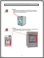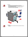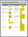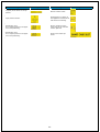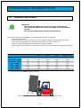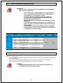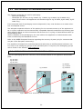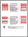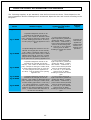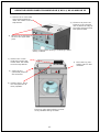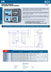
1
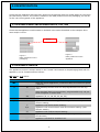
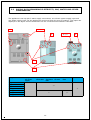
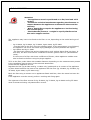
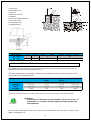
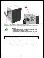
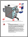
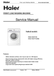
Identification. Product
specification. Definitions.
Preparation of the product for
use.
WF8-11-18-22-33-40-55G400
& G400M Manual
Manufactured on the basis of EN 62079:2002-01 – EN 60204-1
Keep for future consultation.
MA_B008_WF8-11-18-22-33-40-55G400_Chap 1-5_rev.00
30/03/2011
1
Index
1. SUMMARY..............................................................................................................4
1.1 KEY OF INDICATIONS...................................................................................... 4
DOCUMENT RELEASE.............................................................................................. 4
2. IDENTIFICATION....................................................................................................5
2.1 APPLIANCE MARK AND DESIGNATION OF THE TYPE............................................. 5
2.2 APPLIANCE VERSION....................................................................................... 5
2.3 NAME AND ADDRESS OF THE PRODUCER, SUPPLIER AND DISTRIBUTOR................ 6
2.4 PICK-UP AND DELIVERY OF THE APPLIANCE BY THE CARRIER............................... 6
3. PRODUCT SPECIFICATION.......................................................................................8
3.1 GENERAL FUNCTIONS AND RANGE OF APPLICATIONS, DECLARED USE................... 8
3.2 DIMENSIONS AND WEIGHTS (FOR TRANSPORT).................................................. 9
3.3 SUPPLY DATA REGARDING ELECTRICITY, GAS, WATER AND OTHER CONSUMABLES..10
3.4 ENERGY CONSUMPTION, CONDITIONS............................................................. 11
3.5 NOISE EMISSIONS, WASTE, ETC..................................................................... 11
3.6 IP CODE....................................................................................................... 12
3.7 ENVIRONMENT CONDITION AND FUNCTIONING AND STORAGE LIMITS (TRANSPORT)
12
3.8 INFORMATION RELATIVE TO SAFETY, SUMMARY (PERSONAL PROTECTION, NON-DECLARED USE)............................................................................................... 13
THE USE OF ANY ELECTRIC OR ELECTRONIC APPLIANCE MEANS SEVERAL FUNDAMENTAL
RULES MUST BE COMPLIED WITH........................................................................... 13
3.8.1INFORMATION REGARDING RESIDUAL RISKS................................................ 15
4. DEFINITIONS.......................................................................................................18
4.1 SYMBOLS (LABELS) APPLIED TO THE APPLIANCE............................................... 19
5. PREPARATION OF THE PRODUCT FOR USE...............................................................21
5.1 TRANSPORT AND STORAGE............................................................................ 21
5.2 SAFETY PRECAUTIONS BEFORE USE................................................................ 22
5.3 UNPACKING.................................................................................................. 22
5.4 SAFE DISPOSAL OF PACKAGING MATERIALS..................................................... 23
5.5 PREPARATION WORK BEFORE INSTALLATION.................................................... 23
CHECK THE SUPPLY ACCOMPANYING THE APPLIANCE............................................... 25
5.6 INSTALLATION AND ASSEMBLY....................................................................... 26
TO OPEN THE FRONT PANEL IN ALL APPLIANCE MODELS........................................... 26
TO OPEN THE UPPER PANELS IN MODELS KG 8, KG 11, KG 18 AND KG 22................... 27
TO OPEN THE FRONT PANELS IN MODELS KG 33 G400, KG 40 G400, KG 55 G400........ 28
TO OPEN THE REAR PANELS IN ALL APPLIANCE MODELS........................................... 29
TO REMOVE THE RIGHT AND LEFT SIDE PANELS IN MODELS 22 G400, KG 33 G400, KG 40
G400, KG 55 G400............................................................................................... 29
5.6.1MASONRY WORK........................................................................................ 30
5.6.2WATER CONNECTION................................................................................. 31
5.6.3STEAM AND CONDENSATE CONNECTION (ONLY FOR APPLIANCES WITH STEAM
HEATING)................................................................................................. 33
5.6.4DRAIN PIPE CONNECTION........................................................................... 35
5.6.5ELECTRIC CONNECTIONS............................................................................ 36
PARTICULARITY OF THE ELECTRIC CONNECTION IN THE KG 8 G400, KG 11 G400, KG 18
G400, KG 22 G400 MODELS.................................................................................. 38
5.7 REMOVAL OF THE TRANSPORT BRACKETS........................................................ 38
5.8 REGULATION OF UNBALANCING MICRO SWITCH ON ALL MODELS....................... 40
OPEN THE UPPER PANELS IN KG 8, KG 11, KG 18 AND KG 22 MODELS........................ 40
5.9 AIR-BREAK................................................................................................... 41
5.10VENTILATION................................................................................................ 42
5.11ERGONOMIC INSTALLATION OF THE APPLIANCES.............................................. 42
5.12INSPECTION................................................................................................. 43
2
5.13STORAGE AND PROTECTION DURING INTERVALS BETWEEN NORMAL USE ........... 44
5.14RE-PACKAGING TO PREVENT DAMAGE DURING TRANSPORT .............................. 44
5.15ATTRIBUTION OF THE INFORMATION (USERS, OPERATORS, MAINTENANCE EXPERTS)
44
5.15.1 LOCATION OF THE INSTRUCTIONS............................................................ 44
5.16WARRANTY................................................................................................... 45
Translation of the original instructions.
For any claims or observations the reference text is the original one in the manufacturer's language i.e. Italian.
3
1.SUMMARY
1.1KEY OF INDICATIONS
Attention!
• Indicates a procedure of a functioning, assembly or verification
condition which, if not complied with, can cause death or injury/
damage to persons, animals and objects.
Attention!
• Indicates a procedure or functioning, assembly or verification
condition which, if not complied with, can cause damage or
destruction of the appliance or the components of which it is
composed.
• Indicates a procedure or functioning condition, the compliance
with which, as well as being restrictive, can optimise working,
realisations or assembly of the component/s in question in
these instructions.
This manual supplies the instructions for transport, installation, functioning and maintenance of the following appliance models:
• kg 8 G400 - G400M
• kg 11 G400 - G400M
• kg 18 G400 - G400M
• kg 22 G400M
• kg 33 G400M
• kg 40 G400M
• kg 55 G400M
DOCUMENT RELEASE
Ver
00
Document
name
WF G400 use
and installation manual
Network archiving address
I:\110_PROGETTI\P-12_G400_Abilitazione programmazione\P12-54Documentazione-Manuali-Schemi\
Manuale secondo EN 22079_2002-1\
MA_B008_WF8-11-18-22-33-4455_CAP1-5_rev.02.docx
Author
Date
G.G.
29/06/10
This manual has been drawn-up in compliance with the following Standards:
•
•
•
•
•
•
•
•
•
IEC EN 62079:2002-01
EN 62017
EN 60204-1 chapter 17
EN 60335-1 from chapter 7.12
EN 60335-2-7 chapter 7 (and integrations A1, etc. )
ISO 12100-2
ISO 10472-1
ISO 10472-2
ISO 9398-4:2003
4
Aprvd.
Date
2.IDENTIFICATION
Check that the appliance that has been delivered corresponds with the model stated on the transport document, invoice. The model is stated on the label positioned on the packaging, as well as
on the rear closing panel of the appliance.
2.1APPLIANCE MARK AND DESIGNATION OF THE TYPE
Check that theappliance model stated on thelabel is the same described in the transport document and/or invoice.
Model
Figure 2
Plate positioned on the
appliance.
Figure 2
Plate positioned on the
packaging.
2.2APPLIANCE VERSION
The appliance version is always stated in the “model” field stated on thepackaging label and the
appliance, and is characterised as follows:
WFJ XX G4 Y/Y ZZZZ:
Code
Value
WF
J
High spin speed appliances (extraction factor at maximum speed
> 350 G).
M
--XX
G4
Y/Y
With G400M processor that can be programmed from the keyboard.
With standard G400 microprocessor, programmable only via personal computer or smart card.
Appliance (8, 11, 18, 22, 33, 40, 55).
G400 or G400M electronic programmer
E
Appliances without heating (functioning with hot water) or with
electric heating.
V
Appliance with direct steam heating.
E/V
VI
ZZZZ
Description
Appliance with mixed electric and direct steam heating (with
selector switch).
Appliance with indirect steam heating.
GETT
Appliance intended for self-service use (coin operated, automatic
launderettes).
---
Appliance intended for standard use.
5
Gives the possibility to have the following combinations:
WF8G4 WF11G4 WF18G4 WFM22G4
WFM33G4
WFM40G4
WFM55G4
WFM8G4 WFM11G4
WFM18G4
WH70
WH100
WH180
WH220
WH330
WH400
WH550
2.3 NAME AND ADDRESS OF THE PRODUCER, SUPPLIER AND DISTRIBUTOR
Manufacturer:
•
•
•
•
•
•
Name: Grandimpianti Industrial Laundry Equipment ALI S.p.A.
Address: via Masiere 211/c, 32037 Sospirolo (BL) Italy
Tel: +39 (0) 437 848 711
Fax: +39 (0) 437 879 108
E-mail: [email protected]
WEB: www.grandimpianti.com
Supplier (importer):............
IMPORTER STAMP...............
Distributor:........................
DISTRIBUTOR STAMP..........
2.4 PICK-UP AND DELIVERY OF THE APPLIANCE BY THE CARRIER
Attention!
• Before accepting the appliance from the carrier, check the
conditions of the packaging. If this is evidently damaged
on the outside, the appliance may have undergone
consequences. In this case, unpack the appliance in the
presence of the carrier and sign the relative transport
document with reserve.
6
•
•
Any damage due to transport or incorrect storage cannot be
blamed on the appliance manufacturer.
Given the wooden cage packaging on the kg 33 G400, kg 40
G400, kg 55 G400 model, check that the parts projecting, e.g.
dispenser drawer, door handle, isolator switch, etc have not
been damaged.
Declaration of Conformity in compliance with product Standards
7
3.PRODUCT SPECIFICATION
3.1 GENERAL FUNCTIONS AND RANGE OF APPLICATIONS, DECLARED USE
We would like to thank you for the purchase of our appliance. We are sure you will be satisfied
and will obtain the best guarantees if you follow the indications given in this manual carefully.
We would like to inform you that the text to make reference to for any claims or observations,
is that in Italian.
Read the content of this manual thoroughly and keep it with the appliance. It must be easily
accessible.
The recommendations and warnings contained in this manual cannot cover all eventualities,
it is important to have common sense, attention and prudence. These are features that the
manufacturer cannot add to the machine but must be envisioned by the persons carrying out
installation, maintenance and/or using the appliance.
In the event of interventions on the appliance, the manufacturer recommends the use of original spare parts, which must be ordered after consultation of the technical attachment.
Attention!
• Any person using this appliance must read this user manual.
The descriptions and illustrations contained in this manual are not binding; the company
therefore reserves the right, at any time and without forewarning, to update the publication
and/or make any modifications to parts, components and accessories, if this is deemed necessary for improvement or any construction or sales character.
Attention!
• All other use that is not explicitly indicated must be
considered dangerous.
• The manufacturer cannot be considered liable for any
damage deriving from improper, incorrect or unreasonable
use or however not stated in this manual.
• This appliance is not intended for use by children or persons
with reduced physical, sensory or mental capabilities, unless
they are supervised by a person responsible for their safety.
• Modifications of the electric, electronic or mechanical
components and also to their relative positions can only be
made after written authorisation from the manufacturer.
• Children must be controlled so that they do not play with the
appliance.
8
3.2 DIMENSIONS AND WEIGHTS (FOR TRANSPORT)
If the appliance must be transported and/or delivered the following recommendations must be
followed:
• only use the original or similar bed.
• use the manual or electric lifting truck with sufficient lifting capacity and fork length (see
table and fig. 3).
• check that the appliance can exceed all obstacles e.g. stairs, doors etc.
• use the original packaging if the appliance must be shipped.
The product must be stored in closed environment, protected against atmospheric agents.
Appliance model
Gross weight (kg)
Width*
(mm)
Depth*
(mm)
Height*
(mm)
Forks minimum
length X (mm)
Kg8 G400 – G400M
250
750
850
1240
1100
Kg11 G400 – G400M
300
750
930
1290
1100
Kg18 G400 – G400M
485
930
1140
1510
1100
kg22 - G400M
830
975
1190
1620
1100
Kg33 - G400M
1370
1430
1475
2105
1500
Kg40 - G400M
1700
1430
1570
2105
1500
Kg55 - G400M
1770
1430
1750
2105
1500
(*) measurements of the packaged appliance.
Figure 3 Appliance transport.
9
3.3 SUPPLY DATA REGARDING ELECTRICITY, GAS, WATER AND OTHER
CONSUMABLES.
The appliance is set-up with 3 water supply connections, one electric power supply input and
one steam supply input (for the appliances envisioned with this type of heating). The inputs are
displayed in the figure and the dimensions for the connections are stated in the table.
A
B, C, D
A
B, C, D
A
E
F
Appliance model
A, input electric power
supply
B, hard cold
water inlet
C, soft
cold water
inlet
D, hot water inlet
E, steam
inlet
F, water drain
Kg8 G400 – G400M
Kg11 G400 – G400M
3/4”
Kg18 G400 – G400M
3”
kg22 - G400M
Kg33 - G400M
Kg40 - G400M
1”
Kg55 - G400M
10
3/4”
3.4 ENERGY CONSUMPTION, CONDITIONS
Current absorption, hourly steam consumption and water consumption for the different appliances.
Appliance model
Type of
heating
Electric
absorption
(Kw)
Electric
6.75
Steam
0.75
Electric
10.5
Steam
1.5
Electric
14.2
Steam
2.2
Electric
24
Steam
3
Electric
28
Steam
4
Electric
43.5 (opt. 24)
Steam
7.5
Electric
43.5 (opt. 24)
Steam
7.5
Kg8 G400 – G400M
Kg11 G400 – G400M
Kg18 G400 – G400M
kg22 - G400M
Kg33 - G400M
Kg40 - G400M
Kg55 - G400M
Steam consumption
(Kg/h)
7.2
9.5
18
45.8
150
170
170
Total water
consumption (litres)
Hot water only
consumption
(litres)
79 (**)
18 (**)
113 (**)
23 (**)
137 (**)
40 (**)
152 (**)
45 (**)
340 (**)
110 (**)
540 (**)
125 (**)
684 (**)
140 (**)
Consumption calculated on the basis of the ISO 9398-4:2003 Standard.
Data relative to soap consumption are not supplied as the amount of soap depends on
different factors such as: supplier, type, hardness of the water available in the network,
amount of laundry loaded, options selected (e.g. ECO selection).
3.5 NOISE EMISSIONS, WASTE, ETC.
Noise values of the different appliances.
Appliance model
Noise dB (A)
kg 8 – 11 – 18 – 22 G400 – G400M
< 70
kg 33 – 40 - 55 G400M
< 77
Attention!
• During its functioning, the appliance generates water
containing soap/s as well as "dirt" removed from the
laundry.
• The manufacturer cannot be held responsible regarding the
quality and quantity of this waste.
• Follow the local and national Standards in force regarding
the disposal of this waste.
11
3.6 IP CODE
IP codes relative to each appliance model and the descriptions of the code itself.
Appliance model
IP protection rating
Description
IP 24 D
Appliance not protected against mechanical blows.
Protected against sprays of water inclined to 15°.
kg 8 G400 – G400M
kg 11 G400 – G400M
kg 18 G400 – G400M
kg 22 G400M
kg 33 G400M
kg 40 G400M
kg 55 G400M
3.7 ENVIRONMENT CONDITION AND FUNCTIONING AND STORAGE LIMITS (TRANSPORT)
Attention!
• The appliance is suitable only for use in CLOSED
ENVIRONMENTS.
• In the event of long permanence in the deposit, leave the
appliance inside its original packaging, which guarantees
excellent protection.
• In the event of long standstill periods, after the appliance
has been used, follow the instructions given in paragraph
5.7.
Minimum and maximum environmental conditions for functioning.
Functioning conditions
Electric power supply
Model
All models
Water pressure
(KPa)
Steam
pressure*
Room
temperature
(°C)
Relative room
humidity
(%)
V
Hz
Min
Max
Min
(Kpa)
Max
(KPa)
Min
Max
Min
Max
-10 < V
< +10 of
the value
stated on
the label
±1 with
respect
to the
value
stated
on the
label
100
800
50
600
5
35
30
without
condensation
90
without
condensation
* (only for appliances with this type of heating)
Minimum and maximum environmental conditions for storage and transport of the appliances.
Model
Functioning conditions
Room temperature (°C)
All models
Min.
0
Room relative humidity (%)
Max.
Min.
Max.
55
0 without
condensation
90 without
condensation
12
3.8 INFORMATION RELATIVE TO SAFETY, SUMMARY (PERSONAL PROTECTION, NON-DECLARED USE)
Attention!
• This paragraph states all conditions and behaviour for
preventing dangerous conditions for persons, animals,
objects or the environment.
• Read that stated thoroughly and keep this manual near to
the appliance for easy consultation!
• The appliance must only be used by trained persons.
In the event of breakdown and/or malfunctioning:
• disconnect the plug from the socket (if envisioned).
• close the interlocked switch padlock
• close the loading gate valve cocks (hard cold water, hot hard load, steam and and
steam condensate draining if present)
• empty the dispenser from any soap product residues.
During use, cleaning and maintenance, attention must be paid not to access moving parts
with tools or the hands (motors, fans).
In the event of accidents, the manufacturer does not assume any liability for damage to
theoperator or other persons taking place duringuse, cleaning and maintenance of the
appliance.
Do not open the soap drawer when the appliance is functioning (boiling water or soap may
be sprayed pushed by the water pressure).
The appliance has been designed to treat textiles according to the indications stated on the
labels of the garments themselves. Only treat garments, household linens and fabrics for
everyday use.
Do not handle items that have been in contact with inflammable chemical materials.
Hand wash first and dry them in the airto make these substances evaporate completely .
In particular:
THE USE OF ANY ELECTRIC OR ELECTRONIC APPLIANCE MEANS SEVERAL
FUNDAMENTAL RULES MUST BE COMPLIED WITH.
•
•
•
•
•
•
•
Do not touch the appliance with wet or humid hands or feet.
Do not use the appliance barefoot.
Do not leave the appliance exposed to atmospheric agents (rain, salt, sea salt etc.).
Do not allow children to use the appliance or unable persons to use the appliance
without suitable surveillance.
Do not smoke in proximity of the appliance during use.
Do not remove or by-pass safety devices.
Never use direct or indirect jets of water on the appliance, pay attention not to install
it in proximity of zones where this is possible.
13
• Do not touch water or steam pipes even if the appliance is not running.
• Do not wash garments in the appliance, which have the "hand wash" label or relative
symbol.
• Do not use hypochlorite, which could cause the oxidation of some parts of the
appliance (whether electric, electronic or metal).
• Incorrect concentrations of soaps or additives used during the washing phases can
reduce the life span of the appliance and its performance.
Attention!
• The manufacturer is not liable for damage to fabrics washed
using an inappropriate program or soap.
• The manufacturer is not liable for the lack of respect of
indications present on the labels of the garments to be
handled or on the soaps or additives.
• If the labels on the appliance become illegible, replace them.
• The manufacturer is not liable for labels that have been
removed or replaced.
• Respect all local laws relative to safety.
Attention!
• The isolating switch input contacts are always live even if the
switch is in the off position!
• The electric connection and especially the earth wire
connection must be made and checked by authorised staff in
compliance with the local Reference Standards.
• The appliance must have a permanent connection to the earth
clamp and the equipotential clamp must be connected with
other appliances present in the same place.
• The appliance must not be installed on a wooden floor even if
it is reinforced.
• The floor of the premises where this appliance is installed
requires the approval of a structural engineer, who checks
the feasibility depending on the static and dynamic load data
supplied by the appliance manufacturer.
• Do not use the appliance if parts do not function or have been
removed.
• If the plastic membrane positioned on the appliance control
keys is damaged-broken do not use the appliance. Replace
the damaged membrane.
• If the appliance is not used for 2 weeks or more, it is normal
that hydrogen forms in the hot water piping. This highly
explosive gas, must be removed by opening the hot water
piping for a few minutes. During this operation, there must
not be any naked flames present in the room.
• Perform maintenance with the regularity requested in this
manual.
• If body parts should come into contact with the liquid leaking
from a damaged display unit, wash using soap and water.
Seek medical help in the event of accidental ingestion.
• Do not use the appliance if you are not trained to do so.
14
3.8.1 INFORMATION REGARDING RESIDUAL RISKS
Attention!
• Shearing and burns hazard. Do not introduce the hands or
objects into the tub-dispenser connection pipe or into the
protection for airing the inverter.
Attention!
• Shearing hazard. Do not introduce hands or objects between
the fixed and floating parts of the appliance.
15
Attention!
• Burns hazard. The appliance door glass can reach
temperatures of 80 ÷ 90°C (depending on the washing cycle
selected).
Attention!
• Burns hazard. Steam may escape from the appliance
dispenser drawer and the air-break device. Pay attention
to the temperature of the same. Do not introduce hands or
objects through these devices.
16
Attention!
• Burns hazard. The steam intake pipe A, that of the
condensate drain B, the hot water intake pipe C and drain D
can reach high temperatures.
• The steam intake and condensate drain pipes must be
appropriately isolated and protected.
C
D
A
B
Attention!
• Fire hazard. Do not perform the spin cycle with a load of dry
laundry.
17
4.DEFINITIONS
To help understanding of the manual regarding uncommon definitions, below find the definitions and synonyms of some words used.
Appliance = product subject of the manual (washing machine in this case).
User = person that:
•
•
•
•
•
Is assigned to use the appliance.
Has read and understood all pertinent parts of the manual in question.
Is able to perform routine maintenance and clean the appliance.
Is assigned to extraordinary maintenance of the appliance.
It is a qualified person, as expressed successively.
Weighing = washing cycle phase used to identify the weight expressed of the load introduced
into the drum in kg. This phase is composed of 2 distribution ramps. (for kg 8 G400 , kg 11
G400 , kg 18 G400 , kg 22 G400 and relative M versions only).
Soak = washing cycle phase necessary to loosen stubborn dirt to be removed from the fabric.
Prewash = washing cycle phase necessary to loosen and remove dirt of organic nature.
Wash = main phase of the washing cycle necessary to remove dirt from the fabric.
Rinse = phase of the washing cycle necessary to remove the soap and dirt is suspension from
the fabric.
Spin = phase of the washing cycle necessary to remove dirt and soap from the fabric.
Un rolling = final phase of the washing cycle necessary to detach the laundry from the drum
and the final spin.
Protection = part of an appliance used specifically to supply a guard by means of a physical
barrier.
Damage = physical wounding, damage to health of persons, deterioration of assets or the
environment.
Danger = potential source of damage.
Protection device = safeguard (different to a protection) which reduces the risk (mechanical
or electric devices).
Risk = combination of the probability of damage occurring and seriousness of the same.
Informed person = person suitably informed or monitored by a trained person in a way to
allow them to perceive risks and prevent dangers, created potentially by functioning or maintenance of the appliance.
Qualified technician = person with training, knowledge and experience such to allow the perception of risks and prevent dangers that can derive from interactionwith the appliance.
18
4.1 SYMBOLS (LABELS) APPLIED TO THE APPLIANCE
Description
Symbol
Description
At the end of its useful life,
the product must be collected
separately from other waste.
Conformity mark on the
product in compliance
with CE Standards.
Attention, electric hazard:
disconnect the appliance from
the mains before any intervention.
Attention, crushing
hazard: Only use original spare parts. When
repairs and maintenance
have been completed,
restore all panels in their
original position.
Greasing the bearings is mandatory at every indication on
the display.
Attention, read the instructions!
Appliance safety earth connection.
Attention, electric hazard: disconnect the appliance from the mains
before any intervention.
Equipotential connection.
Appliance earth connection.
Burns hazard.
Burns hazard.
Attention, electric hazard,
voltage 400Vac
Room installation and
ventilation requisites.
19
Symbol
Description
Symbol
Description
Capacity of the fuses on the appliance.
Electric master switch
High pressure steam.
Programming n° tokens in
the appliance envisioned for
self-service functioning.
Explanatory text.
N° of copies present in the appliance and positioning.
Slot for insertion of the
smart card in the relevant
reader. Optional.
Explanatory text.
N° of copies present in the appliance and positioning.
Smart card reader. Optional.
20
Symbol
5.PREPARATION OF THE PRODUCT FOR USE
5.1 TRANSPORT AND STORAGE
Attention!
• Check that the appliance has correct space necessary for
use and functioning of the same according to the installation
layouts.
• See technical attachment relative to the layouts.
Proceed as follows if the appliance must betransported and/or shipped:
• Use the original bed.
• Use the manual or electric lifting truck with sufficient lifting capacity and fork length.
• Check that the appliance can exceed all obstacles e.g. stairs, doors etc.
• Use the original packaging if the appliance must be shipped.
• The product must be stored in closed environment, protected against atmospheric agents.
Appliance model
Gross weight (kg)
Width*
(mm)
Depth*
(mm)
Height*
(mm)
Forks minimum
length X (mm)
Kg 8 G400 – G400M
250
750
850
1240
1100
Kg 11 G400 – G400M
300
750
930
1290
1100
Kg 18 G400 – G400M
485
930
1140
1510
1100
kg22 - G400M
830
975
1190
1620
1100
Kg33 - G400M
1370
1430
1475
2105
1500
Kg40 - G400M
1700
1430
1570
2105
1500
Kg55 - G400M
1770
1430
1750
2105
1500
(*) measurements of the NON-packaged appliance.
Figure 4 Dimension of the forks for transport using fork lift truck.
21
5.2 SAFETY PRECAUTIONS BEFORE USE
Attention!
• The following conditions must be verified before installation
and use of the appliance:
{{
{{
{{
{{
{{
The transit zones of the appliance to reach the place
to be used must at least support the static load of
the appliance and transport system.
The floor where the appliance will be installed
must resist the dynamic load and the static load
generated by the appliance.
Wooden floors are not allowed for installation of the
appliance.
Check that the electric absorption of the appliance is
lower than the availability supplied by the electrical
energy body.
Check that the water and steam pressures available
(for appliances envisioned with this type of heating)
is within the accepted values.
Model
Static load
(N)
Dynamic load
Electric absorption Kw (value for version with steam
heating)
KG 8 G400
2840
2330 ±730N, 16 Hz
6,75 (0,75)
KG 11 G400
3330
2740 ±1100N, 16 HZ
10,5 (1,5)
KG 18 G400
5830
4660 ±1,220N, 16 HZ
14,2 (2,2)
KG 22 G400
8080
6452 ±1,626N, 15 HZ
23 (3)
KG 33 G400
14416
12709 ±2,747N, 14
Hz
24 (4)
KG 40 G400
18162
16083 ±2,943N, 14
Hz
43.5 opt. 24 (7,5)
KG 55 G400
19574
17064 ±3,139N, 14
Hz
43.5 opt. 24 (7,5)
Max. water
pressure
(KPa)
Max. steam
pressure
(KPa)
800
600
5.3 UNPACKING
Remove the packaging:
• Cut the straps that fix the cardboard (kg 8 G400, kg 11 G400, kg 18 G400, kg 22 G400)
and lift upwards.
• Remove the sides of the wooden cage (kg 33 G400, kg 40 G400, kg 55 G400).
• After removal of the external packaging, remove the nylon bag.
Attention!
• Put the packaging material in a safe place and that is not
accessible to unauthorised persons.
22
5.4 SAFE DISPOSAL OF PACKAGING MATERIALS
The following materials are used for packaging:
• Nylon (for the bag).
• Cardboard (for the box, for kg 8 G400, kg 11 G400, kg 18 G400, kg 22 G400 only).
• Wood (for the bed on all appliances and wooden cage for kg 33 G400, kg 40 G400, kg 55
G400 only).
If the materials used for packaging must be disposed of, they must be taken to a waste collection and disposal centre.
The adequate separate collection of the packing for the successive start-up of the appliance to
be re-cycled, treatment and environmentally compatible disposal contributes to preventing possible negative effects on the environment and favours the re-cycling of materials that make up
the packaging itself.
Abusive disposal of the packaging by the user leads to the application of administrative sanctions envisioned by the Standards in force.
Refer to the WEEE European Directive regarding the recovery of parts (only for countries that
are part of the European Community).
If it possible to dismantle the individual parts and take them to a differentiated collection centre, refer to the cataloguing groups of the individual parts. If required, the cataloguing groups
can be found in the website: www.euwas.org
5.5 PREPARATION WORK BEFORE INSTALLATION
When the packaging has been removed, check the data stated on the appliance identification
plate.
kg 33 G400
kg 40 G400
kg 55 G400
kg 22 G400
Figure 5 Rear view. Positioning the identification plate.
23
kg 8 G400
kg 11 G400
kg 18 G400
Company name
Model
Motor power
Serial number
IP protection rating of
the appliance
Power Supply Voltage
Year and month
of production
Appliance typeapprovals.
Total electric absorption
Total power
Figure 6 Identification plate present
on the last page of the manual and
on the rear panel of the appliance.
Company name
Model
Serial number
Power supply
voltage and
frequency
Lord weight and
dimensions
Net weight and
packaging volume
Quality control
performed signature
Inspector's signature
Figure 7 Identification plate
present on the appliance
packaging.
Attention!
• Do not power the appliances with voltages and frequencies
outside of the values stated.
• Check that the electric power supply data correspond with
the electric energy supply values.
24
CHECK THE SUPPLY ACCOMPANYING THE APPLIANCE
The following supplies, as per standard, must be found inside the drum. These depend on the
type of appliance and the heating source envisioned. Open the door and control according to the
list given.
Model
Standard supply
Additional supply only for
appliances with steam
heating.
Optional
supply
2 (4 for indirect steam) ¾’’
high temperature gaskets for
steam pipe fitting, 1 steam
filter with ¾’’ connections, 1
(2 for indirect steam) flexible
hose for steam fitting with
¾’’ lock-nut, 1 (2 for indirect
steam) piece of Teflon
braiding to isolate the steam
pipe.
15 tokens for
self service
appliances
supplied with
electro-mechanical coin
operation.
kg 8 G400
kg 11 G400
1 exploded diagrams manual to be
considered an integral part of this
manual, 1 90° rubber 3’ diameter elbow
joint, 2 straps for fixing the rubber hose,
3 water loading pipes with ¾’ lock-nut,
4 x M10 plugs to fix the appliance to the
floor.
kg 18 G400
1 exploded diagrams manual to be considered an integral part of this manual,
1 90° rubber 3’ diameter elbow joint, 2
straps for fixing the rubber hose, 3 water
loading pipes with ¾’ lock-nut, 4 x M10
plugs to fix the appliance to the floor, 1
set of spanners for opening appliance lid.
kg 22 G400
1 exploded diagrams manual to be
considered an integral part of this
manual, 1 90° rubber 3” diameter elbow
joint, 2 straps for fixing the rubber hose,
3 water loading pipes with ¾” lock-nut,
4 x M10 plugs to fix the appliance to
the floor, 1 set of spanners for opening
appliance lid.
2 (4 for indirect steam) ¾’’
high temperature gaskets for
steam pipe fitting, 1 steam
filter with ¾’’ connections, 1
(2 for indirect steam) flexible
hose for steam fitting with
¾’’ lock-nut, 1 (2 for indirect
steam) piece of Teflon
braiding to isolate the steam
pipe.
1 exploded diagrams manual to be
considered an integral part of this
manual, 1 90° rubber 3” diameter elbow
joint, 2 straps for fixing the rubber hose,
3 water loading pipes with 1” lock-nut,3
x 1" water load filters, 4 x M16 plugs
to fix the appliance to the floor, 1 set of
spanners for opening appliance control
panel, 1 rubber elbow with diameter of
60 mm for vent fitting.
2 (4 for indirect steam) ¾’’
high temperature gaskets for
steam pipe fitting, 1 steam
filter with ¾’’ connections, 1
(2 for indirect steam) flexible
hose for steam fitting with
¾’’ lock-nut, 1 (2 for indirect
steam) piece of Teflon
braiding to isolate the steam
pipe.
kg 33 G400
kg 40 G400
kg 55 G400
25
5.6
INSTALLATION AND ASSEMBLY
The following materials are used for packaging:
• Remove the lower front service panel (all models, fixed with 2 – 4 cross head screws).
• Open the upper panel of the kg 8 G400, kg 11 G400, kg 18 G400, kg 22 G400 models,
following the instructions given below.
• Open the control panel of the KG 33 G400, KG 40 G400, KG 55 G400 models, making
reference to the figures shown below.
• Remove the lower rear panel in all models.
• Remove the central rear panel on 22 G400, KG 33 G400, KG 40 G400, KG 55 G400
models.
• Remove the right and left side panels for KG 33 G400, KG 40 G400, KG 55 G400, all fixed
with 2 cross-head screws at the top and 2 hex-head bolts in the lower part.
• Remove the bed, which is fixed using 4 bolts on the same holes to then be used to fix the
appliance to the floor.
TO OPEN THE FRONT PANEL IN ALL APPLIANCE MODELS
kg 33 G400
kg 40 G400
kg 55 G400
kg 8 G400
kg 11 G400
kg 18 G400
kg 22 G400
Figure 8 Open the lower front panel on all models.
26
OPEN THE UPPER PANELS IN MODELS KG 8, KG 11, KG 18 AND KG 22
1) Remove the 4 cross-head
steel screws positioned
under the rubber lid of the
soap drawer.
3) Lift the lid by a few centimetres in the rear part
until it passes the edge of
the upper back piece and
then push forward.
2) Remove the 2 bolts that fix
the lid to the upper back
piece.
Figure 9 upper panel opening in models kg 8 G400
and kg 11 G400.
1) Remove the 4 crosshead steel screws positioned under the rubber
lid of the soap drawer.
3) Insert the key (horizontal) and turn anticlockwise.
2) Insert the key
(horizontal) and turn
anti-clockwise
4) Hold the keys 1 and 2,
turn and push the lid
firmly upwards.
Figure 10 upper panel opening in models kg 18 G400 and kg 22 G400.
27
Release the rod and move it
upwards.
Insert the end point in the relevant hole on the lid.
Figure 11 Positioning the upper panel support rod in the kg 18
G400 and kg 22 G400 models.
TO OPEN THE FRONT PANELS IN MODELS KG 33 G400, KG 40 G400, KG
55 G400
Open the door of the control panel (for KG 33 G400, KG 40 G400, KG 55 G400 only), introducing
the supplied keys into the relevant locks and turning both anti-clockwise. Turn the panel downwards, accompanying it with the hands.
2) Insert the
key (horizontal) and turn
clockwise.
1) Insert the
key (horizontal) and
turn anticlockwise.
3) Keep the keys in
open position and
lower the lid.
Figure 12 Opening the control panel.
28
TO OPEN THE REAR PANELS IN ALL APPLIANCE MODELS
kg 33 G400
kg 40 G400
kg 55 G400
kg 22 G400
kg 8 G400
kg 11 G400
kg 18 G400
Figure 13 Remove the rear panels from the appliance.
TO REMOVE THE RIGHT AND LEFT SIDE PANELS IN MODELS 22 G400,
KG 33 G400, KG 40 G400, KG 55 G400
Figure 14 Remove the side panels. Operate on the upper and lower screws as described.
29
5.6.1 MASONRY
Attention!
• The appliances must be positioned on a flat, level and solid
surface.
• Consult the technical attachment regarding the distances to
respect between the appliances and between these and the
masonry.
• Wet or humid floors require the appliance to be fixed using
the relevant plugs.
• Check that the pressure ÷ weight is equally distributed on
the entire support surface.
The appliance may have to be fixed to the floor or not, depending on the model and type of
floor.
• kg 18 G400, kg 22 G400, kg 33 G400, kg 40 G400, kg 55 G400
•
must be fixed to the floor using the supplied plugs. If this prescription is not followed,
the appliance can move and cause injury/damage to persons,animals and objects.
kg 8 G400 and kg 11 G400
are fitted with rubber feet and are designed to work without being fixed via plugs. In
this case, the floor must have a coefficient of friction greater than 0.5 (adimensional
value).
In the event of a floor with lower coefficient of friction, these appliance models must
also be fixed to the floor using the plugs supplied.
To fix to the floor, make holes with suitable diameter depending on the measurements present
in the installation layouts given in the technical attachment.
Check that the appliance is level.
Regulate the feet (kg 8 G400 and kg 11 G400 only) positioned on al corners of the appliance
or place shims between the base of the appliance and the floor (kg 18 G400, kg 22 G400, kg
33 G400, kg 40 G400, kg 55 G400 only).
Block the feet using a counter-nut in appliances fitted with feet, when the same has been levelled.
If the appliance must be moved, perform levelling and fixing again.
The tightness of the floor screws for kg 22 G400, kg 33 G400, kg 40 G400 and kg 55 G400
must be measured using a dynamometric wrench.
30
1. M8 screw
2. M8 safety nut
3. M8 nut
4. Machine chassis
5. Washer
6. Eventual raised chassis
7. Concrete floor
8. Anchorage bolt
9. Supplied plug
9
4
Load capacity
8 kg
11 kg
18 kg
22 kg
33 kg
40 kg
X7
mm
40
60
X8
mm
150
160
55 kg
5.6.2 WATER CONNECTION
The appliances are set-up for on hot water inlet (max. 90°C) and two cold water inlets, respectively hard and soft. See paragraph 3.3.
Using the table given it is possible to determine the hardness of the water according to the
most used units of measurement .
Classification
mmol/dm3
°dH (German degrees)
°fH (French degrees)
English degrees
Soft
0→1,25
0→7
0→12
0→8,75
Medium
1,25→2,5
7→14
12→25
8,75→17,5
Hard
2,5→3,75
14→21
25→37
17,5→26,3
Very hard
>3,75
>21
>37
>26,3
Set-up the wall gate valves at a distance that does not exceed the length of the pipes supplied.
Attention!
• If soft hot or cold water is not available, set-up on or two "T"
connections in a way to always supply all inlets present on
the appliance.
The average consumption of hot and cold water (total between hard and soft) is given in the
table in paragraph 3.4.
31
Attention!
• Do not connect the water inputs with rigid pipes.
• Only use the supplied pipes.
• Rigid piping is an origin of problems due to the vibrations
generated by the appliance during normal functioning.
• The KG 8 G400, KG 11 G400, KG 18 G400 and KG 22 G400
model appliances have plastic water supply connections:
follow the procedure below for correct closure of the flexible
hose lock-nut.
{{
Tighten the nut manually.
{{
Make a quarter of a turn with a face spanner.
• When assembly has been completed, check that there is no
narrowing or crushing of the hoses used.
Figure 15 kg 8 G400, kg 11 G400, kg 18 G400, kg 22 G400 models water connection
32
M
Figure 16 kg 33 G400, kg 40 G400, kg 55 G400 models water connection
Place the filters indicated with the letter M in the figure, between the water supply pipe and the load
electrovalves. Ca be found among the appliance suppliesinside the drum.
Attention!
• To check the correct tightness of the load pipe lock-nuts and
the filters where present, open the water gate valve slowly
and check for the presence of leaks.
• If leaks should occur, close the lock-nut further and check
again.
5.6.3 STEAM AND CONDENSATE CONNECTION (ONLY FOR APPLIANCES
WITH STEAM HEATING)
The appliances with steam heating are set-up with a M ¾” threaded inlet especially for the
steam, which must be dry saturated.
If the appliance has been requested for heating via indirect steam, a M ¾” threaded connection is also set-up for the collection/recovery of condensate.
The pressure of the inlet steam must be between 50 Kpa and 600KPa.
For steam inlet and condensate collection, refer to the figure (steam inlet label E, condensate
collection label F). In all cases consult the appliance plate data.
33
F
G
E
H
Figure 17 Steam inlet and condensate drain connection (where present).
The pressure recommended for excellent applianceperformance is between 400KPa and
600KPa.
Attention!
• For pressure supplies outside of the values indicated, contact
the manufacturer or the local dealer.
• Cover the flexible steam inlet hose and/or condensate outlet
hose supplied and/or using the Teflon sheath supplied, H
in figure. This is so the operator or maintenance technician
never come into contact with steam or condensate hoses
during their normal activity. These hoses re normally very
hot and can cause burns.
• The steam intake and condensate recovery pipes must be
installed with material able to resist the supply pressure
(max 600 KPa) and temperature of 170°C. The manufacturer
is not liable in the event of damage due to materials used
during installation of the appliance that are not coherent
with these parameters.
• When assembly has been completed, check that there is no
narrowing in the hoses used.
34
Set-up two gate valves for both connections (steam and optional condensate output). These
are indicated in the figure with code G and used to isolate the appliance in the event of maintenance or breakdown.
The filter supplied with ¾“ F/F threading must be inserted between the steam gate valve and
the appliance inlet: this filter will stop impurities and must be cleaned at least once every
month. In the event of a new steam distribution system, it highly probable that the mechanical
filter must be cleaned daily for the first days of functioning.
If the steam appliance is subject to controls by local or national authorities (ISPESL for Italy)
all ISPESL must always be available in the places where the appliance is installed.
5.6.4 DRAIN PIPE CONNECTION
All appliances are fitted with a drain pipe connection for the water during the washing process.
The 3” rubber elbow and two metal straps are supplied for fitting the appliance drains to the
sewer system. Refer to the figure to identify the drain pipe fitting.
Figure 18 Drain elbow connection supplied with all models.
Make sure that the distance between the appliance drain connection and the floor drain is not
longer than the length of the supplied drain elbow.
The water is drained via a motorised valve, which remains open in when there is no voltage
present.
Some special versions envision a second drain for the recovery of the water in some washing
phases.
Follow the particular instructions supplied with the special version.
Maximum drain flow rate for every appliance; 3.5 litres/second.
If several appliances are connected to the same pipe, the diameter of the latter must be increased at the outlet of every engagement. In particular, for one appliance use a 3” (75mm)
drain pipe and for two appliances the pipe must be 4” (100 mm).
Finally, for three appliances, the pipe must be 5” (125 mm).
35
Attention!
• The drain pipe must always be lower than the appliance
outlet and have a diameter that is not smaller than the pipe
supplied.
• The drain pipe must resist temperature of 90°C.
• Position a siphon between the pipe supplied and the drain
pipe.
• Make sure there is no narrowing.
5.6.5 ELECTRIC CONNECTIONS
Attention!
• Installation must be installed according to the manufacturer's
instructions by professionally qualified and certified staff, in
compliance with Standards regarding electric plants in force in
the individual countries both at national and local level.
• Incorrect installation can cause injury to persons and animals
and damage to objects and the environment in general, for
which the manufacturer is not liable.
Earthing techniques.
There are different types of earth systems on the market but for all systems the objectives are identical:
• Limit the potential of the active wires with respect to the earth in normal functioning mode.
• In the event of an isolation defect, contain the voltages between the masses and the earth.
• To allow the intervention of the protection devices in order to eliminate the fault to earth.
• Limit raising of the potential due to faults originating from the medium voltage mains network.
• Contain potential increase when the atmospheric discharge affects the installation or the power
supply network.
Some examples.
NATION
BT public distribution networks (neutral
point connection).
User systems powered
at low voltage.
Specific earth
plants.
GERMANY
TN-C
TN-C and TT
YES
AUSTRALIA
TN-C
TN-C
YES
JAPAN
TT
TT
YES
UNITED KINGDOM
TN-C
TN-C or TN-S
NO
IRELAND
TN
TT
YES
ITALY
TT
TT
YES
BELGIUM
TT
TT
YES
SWITZERLAND
TN
TN-C or TN-S
YES
FRANCE
TT
TT
YES
CHINA
TT
TT
YES
SPAIN
TT
TT
YES
PORTUGAL
TT
TT
YES
NORWAY
IT
IT
NO
36
Attention!
• The appliance, subject of this manual, is set-up for a TT earth
system.
• Certification of the system must be performed by a qualified
technician who verifies and certifies its correct design and
functioning.
• For appliances with steam supply, make sure that the
electric connection cable cannot come into contact with the
steam supply pipe of condensate collection/recovery pipe.
There is a clamp on the rear part of the appliance for the connection of the earth wire,
which must be performed in compliance with the Laws in force.
The manufacturer declines any responsibility when this accident-prevention standard is
not respected.
Regarding this, identify the symbol given below.
This clamp must be connected to the same clamp of the other appliances present in the vicinity and must be then connected to the earth connection via a protective earth circuit alternative to the earth wire supplied with the socket.
Before introducing the cable into the appliance,
check that the cable has a bend that is
lower than the appliance inlet or terminal board,
in a way that drops of condensation onto the cable
do not come into contact with the electrical connections, thanks to this cable.
Power the appliance in compliance with the plate
data of the same and with the distribution system
present.
Use the cable gland mounted on the rear panel of
the appliance to insert the power supply cable and,
after having connected the cables to the isolating
switch supplied with the appliance, block the cable.
Figure 19 Position of the cable gland for insertion of the electric power supply cable on all models.
37
PARTICULARITY OF THE ELECTRIC CONNECTION IN THE KG 8 G400, KG
11 G400, KG 18 G400, KG 22 G400 MODELS.
Attention!
• During the connection of several kg 8 G400, kg 11 G400, kg
18 G400 models,identify the phase that powers the inverter
(on these models the inverters have single phase power
supply) and connect them alternately onto the 3 phases
available, in a way to distribute the load equally.
• Refer to the image to alternate the phases in an equal
manner.
L1
L2
L3
N
Figure 20 Internal view of the appliance, which shows the connection of the electric power supply network
to the isolator switch clamps.
5.7
REMOVAL OF THE TRANSPORT BRACKETS
To prevent damage to the appliance structure during transport, the drum is blocked using clamps
on the front part (1 clamp) and on the rear part (1 clamp for kg 8 G400 and kg 11 G400, 2
clamps for kg 18 G400, kg 22 G400, kg 33 G400, kg 40 G400 and kg 55 G400).
To access these clamps, remove the panels as shown in paragraph 5.6 and remove the clamps
highlighted in figure 31 indicated with 1 (front clamp), 2 (rear clamps) and 3 panels.
Attention!
• Remove the transport clamps before starting the appliance.
• Starting the appliance with the transport clamps mounted
can cause damage to the appliance itself and injury to
personnel.
• Only remove the transport clamps.
• The appliance cannot be transported if the transport clamps
are not fitted.
For transport reasons, the appliance is blocked and this prevents any movement of the washing
unit.
After having removed the transport clamps, re-mount the previously removed panels.
Keep the transport clamps (pos.1, 2) for any future handling of the appliance.
38
Fig. 31 position of transport clamps
Attention!
• DO NOT start the appliance or regulate the unbalancing
micro switch before these clamps are removed.
39
5.8
REGULATION OF UNBALANCING MICRO SWITCH ON ALL MODELS
To access the unbalancing micro switch, access the inside of the appliance: below find the indications on how to proceed depending on the type of appliance to be calibrated.
OPEN THE UPPER PANELS IN KG 8, KG 11, KG 18 AND KG 22 MODELS
Proceed as described in 5.6 to open the appliance panels and obtain access to the area where the
unbalancing micro switch is found.
The unbalancing micro switch intervention rod must be regulated
at the centre of the mobile window.
Operate on
the screws to
regulate the
position of the
unbalancing
micro switch
rod.
Figure 22 Correct position of
the unbalancing
micro switch in
the kg 8 G400,
kg 11 G400, kg
18 G400, kg 22
G400 models.
The unbalancing micro
switch intervention
rod must be regulated
at the centre of the
mobile window.
Operate on the
screws to regulate
the position of the
unbalancing micro
switch rod.
Figure 23 Correct position of the unbalancing micro switch in the kg 33 G400, kg 40 G400, kg 55 G400
models.
40
Attention!
• During periodic maintenance, also control the correct
functioning and positioning of the unbalancing micro switch.
5.9
AIR-BREAK
The appliance is fitted with the “Air-Break” device, which in the event of depressions in the
water supply network prevents the return of non-drinkable water (it could be polluted by the
soap) into the water network.
This device envisions a rear or side outlet (see figure) from which, vapours may escape during
heating.
This device is also necessary for correct readings of the water level.
Never plug this outlet (the vapours created during heating can create pressure and falsify the
level of water measured).
The vapours that escape during the washing program can reach very high temperatures.
KG 22 G400
KG 33 G400
KG 40 G400
KG 55 G400
KG 8 G400
KG 11 G400
KG 18 G400
Figure 24 Air-break device
A 60 mm diameter rubber elbow is supplied with KG 33 G400, KG 40 G400 and KG 55 G400 appliance models for fitting the vent valve to a ventilation channel. If a ventilation channel is not
available, the pipe must beaimed upwards and fixed with the strap, which is also supplied.
41
Air -break pipe connection in the
kg 33 G400, kg 40 G400 and kg 55
G400 models
5.10 VENTILATION
The appliance has forced ventilation that cools the inverter (drum speed regulator).
This ventilation is positioned on the rear-upper part of the appliance.
The ventilation inlet must not be obstructed.
Refer to the figure to identify the position of this ventilation.
KG 33 G400
KG 40 G400
KG 55 G400
KG 8 G400
KG 11 G400
KG 18 G400
KG 22 G400
Figure 25 Position of the air vent necessary for forced cooling of the inverter.
5.11 ERGONOMIC INSTALLATION OF THE APPLIANCES
On installation of the appliances,
pay attention to the ergonomic
aspect.
The appliances must be positioned
in a way that they are easy to
manage from a programming and
laundry loading/unloading point of
view.
If necessary, install the appliances
on a cement baseboard in a way to
raise them or set-up a
platform in a way to allow theoperator to always interact easily with
the appliance.
42
5.12 INSPECTION
After the appliance has been installed, a functioning check must be performed.
Check:
• Fixing the appliance to the floor
• Levelling the appliance
• Connection to the drain
• Connection to the water drain pipes
• Connection of the steam and condensate collection/recovery pipes (appliances with this
type of heating)
• Removal of the transport clamps
• Centring of the unbalancing micro switch
• Connection of the vent pipe (on KG 33 G400, KG 40 G400, KG 55 G400 only)
• Correct electric connection
• Connection of the equipotential clamp
Therefore:
• Open the water gate valves and, if necessary, steam and condensate drain (on
appliances with steam heating).
• Check that there are no leaks present on the load pipe connections.
• Power the appliance via the wall isolating switch and differential, the switch with
interlock on the socket.
• Power the appliance via the isolating switch supplied with the appliance.
• Check the drum is empty
• Put a lid on the dispenser to prevent possible sprays of water and soap escaping during
these checks, which must be performed without lid.
Carry out:
• The calibration operation according to instructions in the FUNCTIONING paragraph and
without laundry!
• The test cycle according to the instruction in the FUNCTIONING paragraph and without
laundry!
When these activities have been concluded, perform a high temperature washing cycle using
suitable cloths and soap.
This is to remove traces of products used during the mechanical processing of the appliance.
During the high temperature washing cycle. Check for any traces of water on the floor or inside
the appliance.
Activate the unbalancing micro switch manually during a spin and check that the latter is interrupted.
At the end of the cycle, check that all soap tanks are clean and no traces of soap are left in any
of the compartments.
When these checks have been performed with positive result, reposition all protections removed. At this point, the appliance can be used by the operators.
Attention!
• The warranty does not cover damage deriving from incorrect
installation.
43
5.13 STORAGE AND PROTECTION DURING INTERVALS BETWEEN NORMAL USE
In the event of appliance standstill for long periods, follow the indications given below:
• Remove the power supply to the appliance.
• Disconnect the socket.
• Close the water gate valves (all) and the steam gate valves if the appliance should have
this type of heating.
• In the event of heating with indirect steam, close the condensate drain/recovery gate
•
•
•
•
valve. Disconnect the drain/condensate recovery pipe. Drain the condensate present in
the appliance. Re-connect the pipe when this operation is finished.
Dry the drum, the door gasket and the dispenser drawer.
Remove soap residues.
Leave the door open and protect the appliance possibly with a plastic bag that is supplied
with the same.
Keep the appliance in a closed place and with envisioned environmental conditions.
5.14 RE-PACKAGING TO PREVENT DAMAGE DURING TRANSPORT
Attention!
• Use the original packaging and bed if the appliance must be
transferred.
5.15 ATTRIBUTION OF THE INFORMATION (USERS, OPERATORS, MAINTENANCE EXPERTS)
Attention!
• The instructions contained in this manual must be
distributed to all personnel that interact with appliance in
any way.
5.15.1LOCATION OF THE INSTRUCTIONS
These instructions are supplied with the appliance and are attached to thepackaging in an adhesive bag, which identifies the content.
This manual must accompany the appliance from receipt until it is dismantled.
Attention!
• Any person using this appliance must read this user manual.
• The appliance must only be used by trained persons.
• Keep this manual in a place that is easily accessible for
future consultation.
• If this appliance is transferred to another owner, this manual
must accompany the appliance.
44
5.16 WARRANTY
The warranty has duration of twelve (12) months from the date ofpurchase of the appliance or
an integral part of the same.
The warranty consists in the replacement of any faulty parts for ascertained manufacturing
causes and applied directly to your dealer.
Labour is always at the purchaser's expense as are delivery and packaging costs as are the
risks of transport.
The warranty is subject to return of the pieces damaged in FREE PORT and the simultaneous
communication of the data regarding the model, the serial number and the fault of the appliance on which the detail was mounted.
The warranty is not applied to appliances that have been damaged due to negligence, incorrect
connection, unsuitable installation, failure to comply with mounting and user instructions and
however altered by unauthorised staff. It is also not applied if the serial number has not been
altered, deleted or removed or is not known.
The warranty does not cover the following material:
• Parts subject to normal wear such as belts.
• Membranes of the electrovalves, gaskets and rubber parts in general.
Electric and electronic elements such as motors, coils, resistances, circuit board,
inverters etc.
45