1
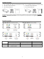
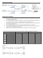
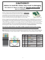
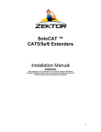
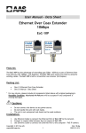
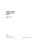
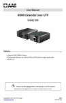
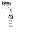
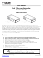
User Manual
PoE Ethernet Extender
Over One Coax Kit
EPOC-POE-100K
EPOC-POE-100-SV
Host/Server Side
N-7a
EPOC-POE-100-IPC
Camera Side
N-7b
Thi s Ethernet extender consists of one EPOC-POE-100-SV Unit (host/server side) and one
EPOC-POE-100-IPC Uni t (ca mera side). It can transfer Ethernet signal of IPC-Unit to carrier s ignal
though coaxial cable or network ca ble and extend to SV-Unit, then transfer ca rrier signal to
Ethernet s ignal a nd tra nsmit power synchronously. SV-Unit could use 48~57V DC power s upply
or PoE power s upply, which fully meets the needs of long distance Ethernet signal transmission
a nd power s upply. It i s widely used in coaxial ca ble and network ca ble mixed wiring security
s urveillance and network rebuilding projects.
Features
•
•
•
•
•
•
•
•
•
..
Us es coaxial ca ble or network ca bles to tra nsmit Ethernet a nd power s ignals
Ma x. di stance up to 500m / 1600ft vi a coaxial ca ble; 400m / 1300ft vi a network cable
Adopt a dvanced tra nsmission and power supply technology
Ethernet delay l ess than 1ms; meets point-to-point application
Sta ndards: IEEE802.3 10BASE-T, IEEE802.3u 100BASE-TX, IEEE802.3af/at
Protecti ons: Excellent ci rcuit isolation protection, superior product a nti-thunder,
a nti -static a nd a nti-interference ca pability
Appearance: Meets MIT rack installation s tandard
Pl ug-and-play, no setting required
48~57V DC power s upply (Not included) (EPOC-POE-100-SV)
Please read the Manual before attempting to use this product.
Specifications and appearance are subject to change without notice.
Copyright © 2014 AAS Technology
www.AAS.com.tw
N-7
R201501-V06
Disposal of Old Electrical & Electronic Equipment (Applicable in the European
Union and other European countries with separate collection systems).
This symbol on the product or on its packaging indicates that this product shall not be treated as household
waste. Instead it shall be handed over to the applicable collection point for the recycling of electrical and
electronic equipment. By ensuring this product is disposed of correctly, you will help prevent potential
negative consequences for the environment and human health, which could otherwise be caused by
inappropriate waste handling of this product. The recycling of materials will help to conserve natural
resources. For more detailed information about recycling of this product, please contact your local city
office, your household waste disposal service or the shop where you purchased the product.
Caution
..
This product has been tested for conformance to safety regulations and requirements. However, like all
electronic equipment, this product should be used with care. Please read and follow the safety instructions
to protect yourself from possible injury and to minimize the risk of damage to the unit.
1. Handle this product with care
Avoid any shock or bumping of the product. Improper handling could damage the product. Do not handle
the unit with wet hands. Provide proper ventilation and air circulation and do not use near water.
2. Requires a proper operating environment
This product is not waterproof and is designed for indoor use. The allowable temperature range for
operation of this product is between 0°C~55°C / 32°F~131°F.
3. Check the power source voltage
The power source voltage should be within the specified range. (Product must meet the specifications).
4. Objects and liquid entry
Never push objects of any kind into this product as this may touch dangerous voltage points of short out
parts that could result in a fire or electric shock. Never spill any kind of liquid on the product.
5. Cleaning
Do not use liquid or aerosol cleaners to clean this unit. Always unplug the power to the device before
cleaning.
6. Servicing
Do not attempt to service this product by yourself as opening or removing covers may expose you to
dangerous voltage or other hazards. Refer all service to qualified servicing personnel.
2
Package Contents
..
1. One (1) EPOC-POE-100-SV unit (host/server s ide)1. One (1) POEOC-100-IPC uni t (camera side)
2. Two (2) Ea r Mount Brackets
2. Two (2) Ea r Mount Brackets
3. One (1) Us er Ma nual
3. One (1) Us er Ma nual
For a ny returns, please i nclude a ll components listed above with original packaging in Resalable
Condition. Absolutely No Returns wi ll be a ccepted i f any component is missing/damaged.
Parts & Functions
EPOC-POE-100-SV (Hos t/Server Si de):
LED Status
Flash
On
..
EPOC-POE-100-IPC (Ca mera Side):
PoE In / Out (RJ-45)
Yel l ow l i ght
Green l i ght
n/a
Indi ca te communi ca ti ng
Indica te PoE output / DC Indicate cable connecti on
power s uppl y
3
EPOC RJ-45
Yel low / Green l i ght
n/a
Indi ca te ca bl e
connection i s normal
Application Diagram
..
Hardware Installation
..
1.
2.
3.
4.
5.
6.
Pl ease turn off the signal source and the device's power; i nstallation with power s till
on ma y da mage the devi ce.
Us e network cable to connect PoE IN port of SV-Unit and PoE Ethernet switch (if it's
not PoE s witch, then need to use 48-57V power s upply for SV-Unit).
Us e a nother network ca ble or coaxial ca ble to connect Ethernet port of SV-Unit a nd
Ethernet port of IPC-Unit
Us e a network ca ble to connect IP ca mera with PoE OUT port of IPC-Unit.
Check i f the i nstallation is correct a nd devi ce is good; make s ure all the connections
a re reliable and power for the s ystem.
Ma ke sure every network device has power s upply a nd is working normally.
** Table 1 (The test data in Table 1 based on the test method in Application Diagram shown above)
Power Supply
PoE Ethernet Power Supply
54V DC Power Supply
SV <--> IPC Cable
75-5
CAT5e
75-5
CAT5e
100m
Bandwidth (Mbps)
92.6
91.2
92.6
91.2
Load Capacity (W)
16.1
17.2
23
23
200m
Bandwidth (Mbps)
91
84.2
91
84.2
Load Capacity (W)
10
12
17
22
300m
Bandwidth (Mbps)
90.8
74.5
90.8
74.5
Load Capacity (W)
8
9.1
12
16
400m
Bandwidth (Mbps)
90.5
55.7
90.5
55.7
Load Capacity (W)
5
6.5
10
12
500m
Bandwidth (Mbps)
83.7
/
83.7
/
Load Capacity (W)
4.5
/
8
/
**Picture 1
4
Technical Specifications
Kit Model
Model
Application Location
Power Supply
Voltage Range
Power Consumption
Power Voltage
Output Voltage
Ethernet Port
Transmission Distance
Transmission Medium
PoE Agreement
PoE Power Supply
Ethernet Standard
Ethernet Delay
LED Status Indicator
ESD Protection
Communicating Port
Anti-thunder Protection
MTBF Stability
Working Temperature
Storage Temperature
Humidity (non-condensing)
Dimensions (L x W x H)
Net Weight
..
EPOC-POE-100K
EPOC-POE-100-SV
EPOC-POE-100-IPC
Host/Server Side
Camera Side
Powered by
From PoE switch or
EPOC-POE-100-SV
power supply
through coaxial cable
48V~57V DC
< 2W
48V-57V
N/A
N/A
12V DC
EPOC Port: 0~100Mbps ; Ethernet Port: 10/100Mbps
Coaxial Cable: 500m / 1600ft (max.)
Network Cable: 400m / 1300ft (max.)
Transmission bandwidth changes with transmission distance**
(refer to Table 1 and Picture 1)
75-5 Above Coaxial Cable and CAT5e/6
Support IEEE802.3af, IEEE802.3at
Support End-span and Mid-span
IEEE802.3 10BASE-T, IEEE802.3u 100BASE-TX
< 1ms
PoE IN/OUT Port: One indicates PoE switch or DC power
status (RJ45 yellow), one indicates Ethernet signal
transmission (RJ45 green);
EPOC Port: Indicates signal transmission (RJ45 yellow/green)
1a Contact Discharge 3 Level
1b Air Discharge 3 Level
Per: IEC61000-4-2
Per: IEC61000-4-5 level 3
> 30,000h
32°F ~ 131°F / 0°C ~ 55°C
-40°F ~ 185°F / -40°C ~ 85°C
0~95%
82 x 63.2 x 25 mm / 3.23 x 2.49 x 0.98 inches
153g / 5.4oz
154g / 5.43oz
*Specifications are subject to change without notice
Troubleshooting
•
•
•
•
•
..
Pl ease confirm if the installation i s correct.
Pl ease confirm if the RJ45 ca ble order is i n a ccordance with the EIA/TIA568A or 568B
i ndustry s tandards (Refer to page 7).
The ma ximum transmission distance i s depends on the signal s ource a nd ca ble quality;
do not exceed the maximum tra nsmission distance.
Pl ease replace a normal device with a faulty one to check i f the devi ce is broken.
If the problem still exists, please contact supplier.
5
Limited Warranty
..
LIMITED ONE (1) YEAR WARRANTY AND EXCLUSIONS
Manufacturer warrants to the original consumer purchaser and not for the benefit of anyone else that this product at
the time of its sale by Manufacturer is free of defects in materials and workmanship under normal and proper use for
one (1) year from the purchase date. Manufacturer's only obligation is to correct such defects by repair or
replacement, at its option, if within such one (1) year period the product is returned prepaid, with proof of purchase
date, and a description of the problem. This warrant excludes and there is disclaimed liability for labor for removal of
this product or reinstallation. This warranty is voided if this product is installed improperly or in an improper
environment, overloaded, misused, opened, abused, or altered in any manner, or is not used under normal
operating conditions or not in accordance with any labels or instructions. There are no other implied warranties of
any kind, including merchantability and fitness or a particular purpose, but if any implied warranty is required by
the applicable jurisdiction, the duration of any such implied warrant, including merchantability and fitness of or a
particular purpose, is limited to one (1) year. Manufacturer is not liable for incidental, indirect, special, or
consequential damages, including without limitation, damage to, or loss of use of, any equipment, loss sales or
profits or delay or failure to perform this warranty obligation. The remedies, provided therein are the exclusive
remedies under this warranty, whether based on contract, tort or otherwise.
www.AAS.com.tw
6
CAUTION!!!
Failure to read this notice may result in damaging
the camera or device in which the warranty will be voided
due to installation error.
When using any type of RJ45 jack powered balun, a Cable Tester
mus t be used to ensure proper connection. Ma ny i ndivi duals ca n
ma ke RJ45 connections easily, however mistakes can be made.
When making connections for powered baluns, make sure to test
the connectivity a nd ensure proper a lignment on both sides.
Cable Tester
When using passive or a ctive baluns, the alignment of the cable is imperative to the success of
the operation. Use a Ca ble Tester because it i s a very s imple, easy to fi nd tool that ca n save a
huge headache. For example, if one of the vi deo wi res a ccidentally gets crimped i nto the power
s i de and the powered balun is then hooked up to the camera, both the ca mera and the balun
ha ve just burned out. This i s an extremely costly mistake, not only i n dollars but i n ti me as well.
How l ong does i t take to test the RJ45 using a Ca ble Tester? Less than one minute.
The new terms and conditions state: When an RMA is requested and the product has been
burned by bad RJ45 connections, the product is NO LONGER covered under warranty.
Note: Whichever way the RJ45 is terminated on one end of the cable, IT MUST BE THE SAME ON
THE OTHER SIDE for either TIA/EIA 568A or TIA/EIA 568B. Below is an example of TIAEIA 568B.
12 345 67 8
P air 3
P air 2 P air 1 P air 4
1
2
3
4
5
6
P in
P air
1
2
O r ange / White
2
2
O r ange
V ideo –
3
3
Gr een / White
P ower –
4
1
Blue
P ower –
5
1
Blue / White
P ower –
6
3
Gr een
P ower +
7
4
Br own / White
P ower +
8
4
Br own
P ower +
T IA /EIA 5 6 8 B
7
C olor
C har acter
V ideo +
MADE IN CHINA
Copyright © 2014 AAS Technology
www.AAS.com.tw
8
N-7
R201501-V06