1
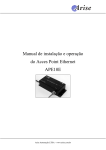
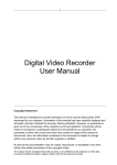
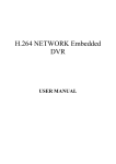
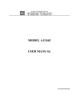
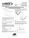
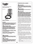
Digital Video/Audio/Data Fiber Transmitter & Receiver USER MANUAL Quality Commitment 1、Since the date of purchase ,the products have a one-year warranty after-sales service. If you do prove that product has quality problems under this warranty period, according to testing and determine, we will provide products for free repair or replacement.(quantity fee) 2、The result of damage caused by negligence and misuse is not within the scope: (1) Accessing to the inappropriate power; (2) Do not meet environmental conditions of use; (3) Not in accordance with the manual; (4) Lightning, water, fire, etc; (5) All the damage caused by human factors; 3、Such as the failure is existed during the process of use, the user shall not disassemble it, quality issues will need to be noticed to this company, and provide the appropriate cooperation for the service which will be carried out by us. 4、We committed that the following service of repair or replacement, as quality problems caused by that not covered under the scope of warranty, and the purchase of our products had exceeded the quality warranty period. If the problems could be repaired in the product case, we can offer paid service. 5、Final interpretation and the power of amendment, both are owned by the company. Installation and Service Notice Declaration: In order to avoid personal injury, and avoid unnecessary damage to other products connected with it, as well as to install this product more smoothly, we solemnly suggest: Before connection、installing this product, please be sure to read the instructions carefully, and pay attention to the note. According to the requirement, In order to prevent a variety of potential injury! Caution: To maintain the reputation of our company, All products are within the tamper labels, please do not disassemble the machine. If the tamper labels were damaged, the product will no longer enjoy the right of free maintenance, and retain appeal right for the company's intellectual property. Before using this product, please read this manual carefully and properly preserve it, be sure to comply with all operational procedures! Before using this product, please pay particular attention to anti-static measures, which can avoid the equipment damaged. The company reserves the right to change the product,and it is without notice. Contents 1、Introduction ........................................................................................ 5 2、Application ......................................................................................... 5 3、Product Appearance .......................................................................... 6 4、Products Function .............................................................................. 7 5、Product Characteristics .................................................................. 8 6、Technology Parameters ..................................................................... 8 7、Products Description........................................................................ 13 8、Status Indication .............................................................................. 27 9、Products Installation Stepsd and Use Method ................................. 28 10、Common troubleshooting methods ................................................ 30 11、Packing List ................................................................................... 31 1、Introduction Digital video fiber transmitter & receiver possess core intellectual property rights, use special ASIC, adopt international most advanced Digital video and fiber transmission technique. JLWS series Digital video fiber transmitter & receiver can real time transmit up to 128 channels video,1-32channels (single-direction or bi-direction)data and audio and 1/0 and 1-4channels 10/100M Auto-adaptive Ethernet signal over one fiber with high quality. It is extremely flexible with the ability to add/ drop video, audio, RS232/RS422/RS485, E1, 10/100M Ethernet ports via plugging in/out our field-proven service cards. It is used in high-end video surveillance fields widely. Our products process video by high-frequency digit, use un compressed technique, avoid the adjustment trouble and low SN R and bad working stability of analog video transmitter and rec eiver. Supply broadcast standard video, hi-fi audio and high spe ed data transmission. It is easy to construct tree, star, ring and mix topology surveillance network and support more complex s urveillance group network. Our products adopt modularization design, support expand f unctions, remote end equipment support 1+1 fiber link protection, can automatic isolate fault node to ensure other nodes working normally. Also, It support SNMP module to manage remote an d local equipments. Analog signal and PAL,NTSC,SECAM etc signals Auto-com patible. Each video channel adopt 8bit digit coding, Baud rate is 0-2Mbps.Digital channel use gigabit transmission platform to tra nsmit. Transmission distance of Standard type is 20KM, Max tra nsmission distance is 120km without relay. 2、Application ◆ High way &Tall station surveillance ◆ Speedway & Railway remote surveillance ◆ Public security surveillance 5 ◆ ◆ ◆ ◆ Surveillance and cable TV system Intelligent traffic monitor system High quality video conference Broadcast and TV program transmission Long-distance multimedia teaching Industrial Closed Circuit Television Surveillance Custom, Airport, Warehouse video monitor Supermarket, Bank Hall& ATM machines video surveillance Smart building, Government office etc safety & protection system 3、Product Appearance 6 4、Products Function Support PAL, NTSC, SECAM. Support 24bits mono, stereo, bi-directional, balanced and non-balanced audio transmission. Support RS485/RS232/RS422, rate up to 2Mbps / sec. Support CAN bus. Support 10/100M Ethernet , with adaptive interface and line of automatic switching capabilities。 Support access control, switches, alarm. Support phone, can also pass the hotline. Support intercom signal. 5、Product Characteristics ◆ Digital fiber transmission platform, Multi-operation flexible setting, save investment to build complex network 7 ◆ No EMI,RFI etc ◆ Support Audio, Data, Phone etc cross connection function and remote set on management platform ◆ Perfect High-grade Thunderbolt, Surge, ESD protection design to ensure long time stable working ◆ Good Data, Audio, Ethernet, Talk-back etc electromagnetism compatible feature ◆ Large-scale Proprietary IC Core and high-speed DSP technique ◆ Auto-switch Fiber protection (<20ms),improve the reliability of system ◆ Support Audio, Data regenerate and relay ◆ Modularized and industrialized design ensuring reliability and flexibility ◆ Adopt WDM/CWDM/DWDM technique ◆ Auto PAL/NTSC/SECAM Compatible ◆ Indicators for Power Supply, Video, Optic-link and Data-loop ◆ Large capacity of gigabit optical fiber transmission allowing of easy upgrade ◆ Card type, Stand-alone type,19 inch 1U/2U standard case and 4U chassis optional 6、Technology Parameters (1) Optical Parameters No. Item 1 Wavelength 2 3 4 Output power Sensitivity Single and width 5 Distance 6 Max power budget Parameter 850/1310nm(MM);1260~ 1360 , 1470~ 1610(SM) 0 dBm ~ -3 dBm/-5 dBm ~ -10 dBm ≤-34dBm 1.25G/2.5G MM: 0-1km SM: 0-20km,0-60km,0-80km 15dBm/20dBm/25dBm/30dBm (2) Video 8 No. 1 2 3 4 5 6 7 8 9 10 11 12 13 Item Parameter Channels number 1128 Signal format PAL/NTSC/SECAM Input/Output electrical 1Vp-p level Input/output 75Ω impedance Bandwidth of each 8 MHz channel Frequency 16MHz Quantization grade 8/10bit Differential gain 1%(representative value) Differential phase 1˚(representative value) S/N ratio 65/70dB(representative value) Color/Light delay time 10ns(representative value) difference Color/Light gain ±10%(representative value) difference Connector BNC Note:Support Forward, Reverse or Bi-direction Video (3) Audio No. 1 Item Input impedance(Line-in) 4 5 6 7 8 Output impedance(Line-out) Input/Output electrical level Audio bandwidth Frequency Quantization grade S/N ratio Total harmonic distortion 9 Connector 2 3 Parameter 600/47K, Balance/Unbalance 600/10K, Balance/Unbalance 2Vp-p 20Hz20KHz 48KHz 24bits 85dB 0.1% Industrial pressure connector/RJ45/RCA 9 optional Note:Support Forward, Reverse or Bi-direction Audio (4)PTZ, Keyboard, Matrix control data ports(support multiway data, all keyboard, Matrix, DVR, Alarm data compatible) Connector:RJ45,DB9F,DB25F,Industrial pressure connector optional No. Item RS-232 1 Data speed 2 Data error rate 3 Data protocol 4 Network connection RS-485 1 Data speed 2 Data error rate 3 Max channels 4 Max distance 5 Data protocol 6 Network connection Parameter DC-115.2Kbps <10E-12 Support RS-232 protocol totally Support forward, reverse, bi-direction and Point to Point, Point to Multipoint connection DC-115.2Kbps/DC-2Mbps <10E-12 128 1200 meters Support RS-485 protocol totally, including RS-485 polling or Modbus Support forward, reverse, bi-direction and Point to Point, Point to Multipoint connection RS-422 1 2 3 4 Data speed Data error rate Max distance Data protocol 5 Network connection DC-115.2Kbps/DC-2Mbps <10E-12 1200 meters Support RS-422 protocol totally Support forward, reverse, bi-direction and Point to Point, 10 Point to Multipoint connection Machester Code 1 Data speed 2 Data error rate 3 Max distance 4 Data protocol 5 Network connection DC-2Mbps < 10E-12 1200 meters Support Machester protocol totally Support forward, reverse, bi-direction and Point to Point, Point to Multipoint connection (5) Asynchronism Data No. 1 2 3 4 5 Item Data ports Parameter RS232/RS485/RS422/ Manchester code Working mode Full-duplex/Half-duplex Data speed DC-115.2Kbps Data error rate <10E-12 Connetor Industrial pressure connector/RJ45 optional Note:Support Forward, Reverse or Bi-direction Data (6)Alarm,1/0,Remote control port(support Multi-ways, full transparent transmission) Alarm Interface No. Item Parameter RJ45,DB9F,DB25F,Industrial 1 Alarm,1/0 connector pressure connector Any Active or Passive alarm,1/0 input. Support 2 Alarm,1/0 input signal TTL,RS-232/422/485 or Passive switch button Any Active or Passive alarm,1/0 output. Support 3 Alarm,1/0 output signal TTL,RS-232/422/485 or relay point output connection (7) 10M,10/100M Ethernet connector(support multiways or mu 11 lti-pieces Ethernet electrical interface, Optical interface switch b uilt-in function) Ethernet Interface No. 1 Item Connector 2 10M connector 3 10/100M Auto-adaptive connector Parameter Cat5 RJ-45 connector Full-duplex or half-duplex, IEEE 802.3 10Base-T Compatible Full-duplex or half-duplex, MDX, IEEE 802.3 10/100Base-T Compatible (8). Dimension, power supply and power consumption No. Item Parameter Wall mount or stand-alone type 1 MINI Dimensio 90mm(L) 70mm(W) 25mm(H) n 2 Power +5V input, outside power adapter supply connected 3 Power consumpti 5W on 1U rack type 1 Dimensio 1U 200mm(L) 482mm(W) 44mm(H) n 2 Power AC 110V - 220V;DC +5V supply 3 Power consumpti 15W on 2U rack type 1 Dimension 2U 256mm(L) 482mm(W) 88mm(H) 2 Power supply AC 110V - 220V input;DC +5V ; 2U concentration of power supply 12 3 Power 80W consumption 4 Slot number 14 4U rack type (max 16pieces card can be inserted into one 4U rack) 1 Dimension 4U,240mm(L) 482mm(W) 176mm(H) 2 Power supply AC 110V - 220V input;DC +5V ;5U concentration of power supply,support dual power supply 3 Power 100W consumption 4 Slot number 16 7、Products Description Digital Video Fiber Transmitter &Receiver including one piece TRANSMITTER and one piece RECEIVER. Transmitter and Receiver must be used in pair, and can’t connect to other type or other producer’s Digital Video Fiber Transmitter &Receiver to use together. 1. One Channel Economical Type (MINI type) Mini type Digital Video Fiber Transmitter & Receiver is simple, small, light and easy to install. The function and quality is same to common type Transmitter & Receiver. Mostly be used in small project. Good to sporadic surveillance and multipoint surveillance. This type product support one channel video, and one data transmission over one fiber. Detail, please refer to MINI type function table. Figure1:MINI (1) MINI panel diagram 13 JL-1V1D panel JL-1V panel (2) Interface definition MINI Interface definition No. Mark 6 A 7 B 8 Video 5 OPT 9 5V Connector A channel 485+ B channel 485Video signal Fiber connector Power port Remark Connect the A of PTZ Connect the B of PTZ Transmitter Video port for signal input Receiver Video port for signal output Fiber connector,FC/SC/ST (3) Indicator’s instruction MINI LED No. Mark 1 PWR 2 3 SYN V1 RXD TXD 4 Connector Power LED SYN LED Video LED Data LED Remark Power normal is red Fiber connector normal is green Video signal normal is green Data input/output normal is green (4) MINI type function table 14 No. 1 2 Item Video RS485 Function Forward direction Video 1 channel Single-direction or Bi-direction RS485 Max channel Number 1 1 channel Bi-direction;OR 1 channels Reverse direction (5) Technical parameter Connector: Optical:FC/ST/SC(Optional) Video:BNC 75Ω Data:Industrial pressure connector 1/0:Industrial pressure connector Power supply: AV power supply:AC 110V - 220V 50HZ Power consumption:≤3W Working environment: Working temperature: -40 ℃~+70 ℃ Storage temperature: -50 ℃~+85 ℃ Humidity: ≤95% (non-condensing) Dimension: Stand alone:90mm(L)×70mm(W)×25mm(H) Color: Iron gray; Material:Iron Connector: Optical:FC/ST/SC(Optional) Video:BNC 75Ω Data:Industrial pressure connector 1/0:Industrial pressure connector Power supply: AV power supply:AC 110V - 220V 50HZ 15 Power consumption:≤3W Working environment: Humidity: ≤95% (non-condensing) Dimension: Stand alone:90mm(L)×70mm(W)×25mm(H) Color:Silvery white; Material:Duralumin case 2. 1 ~8 Channels Stand Alone Type 1 ~8 channels stand alone type Transmitter&Receiver is small, light, easy to install and high acclimatization. Audio, Data(RS232/ 485/422,CAB etc),Ethernet,1/0 are Flexible to configure. Detail, please refer to 1~8 Chs Common type function table. (1) 1~4 Chs standard panel (2) 1~4 Chs Indicator’s instruction No. Mark 1 PWR 2 SYN Connector Power LED SYN LED Remark Power normal is red Fiber connector normal is green 16 3 4 5 6 7 8 V1 V2 V3 V4 TXD RXD Video LED Video LED Video LED Video LED Data LED Data LED 1 chs video signal 2 chs video signal 3 chs video signal 4 chs video signal Data output normal is green Data input normal is green 1~4 Chs Interface definition No. Mark 9 OPT 10 11 DD+ 12 A1 13 A2 14 GND 15 A3 16 A4 17 18 19 20 21 CH1 CH2 CH3 CH4 5VDC Name Fiber connector First channel 485+ First channel 485The first audio output The second audio output Grounding for data/audio The first audio input The second audio input 1 chs video signal 2 chs video signal 3 chs video signal 4 chs video signal Power port Remark Fiber connector , FC/SC/ST Connect the A of PTZ Connect the B of PTZ Transmitter Video port for signal input Receiver Video port for signal output (3) 5~8 Chs standard panel 17 (4)1~8 Chs Indicator’s instruction No. Mark 1 PWR 2 3 4 5 6 7 8 9 10 11 12 SYN V1 V2 V3 V4 V5 V6 V7 V8 TXD RXD Connector Power LED SYN LED Video LED Video LED Video LED Video LED Video LED Video LED Video LED Video LED Data LED Data LED Remark Power normal is red Fiber connector normal is green 1 chs video signal 2 chs video signal 3 chs video signal 4 chs video signal 5 chs video signal 6 chs video signal 7 chs video signal 8 chs video signal Data output normal is green Data input normal is green 1~8 Chs Interface definition No. 13 Mark OPT Name Fiber connector Remark Fiber connector FC/SC/ST , 18 14 15 DD+ 16 A1 17 A2 18 GND 19 20 21 22 23 24 25 26 27 CH1 CH2 CH3 CH4 CH5 CH6 CH7 CH8 5VDC First channel 485+ First channel 485The first audio output or input The second audio output or input Grounding for data/audio 1 chs video signal 2 chs video signal 3 chs video signal 4 chs video signal 5 chs video signal 6 chs video signal 7 chs video signal 8 chs video signal Power port Connect the A of PTZ Connect the B of PTZ Transmitter audio port for signal input Receiver audio port for signal output Transmitter Video port for signal input Receiver Video port for signal output Technical parameter Connector: Optical:FC/ST/SC(Optional) Video:BNC 75Ω Data:RJ45/DB9/ Industrial pressure connector Audio:Industrial pressure connector Ethernet:RJ45 1/0:Industrial pressure connector Power supply: AC power supply:220VAC±30% 50HZ DC-48V:48VDC±20% DC+24V:24VDC±20% Power consumption:≤5W Dimension: Standalone:138(L)×175(W)×30(H)mm Card type:4U rack centralized installation 19 (5)4U rack-mountable expansion 1-8 1~8 chs extended optical video, increase the variety of expansion interfaces based on the common type,its function has been improved so much. Please refer to the configuration table of functions. (4u) Extended stand-alone type No. Item 1 2 Video Audio 3 4 5 6 RS232 RS485 CAN Bus 1/0 7 Power Function Forward video Single-direction or Bi-direction Audio RS232 RS485 Support CAN Bus Single-direction or Bi-direction Double backup power support Max channel Number 64 64/32 16 16 16 16 2 Technical parameter Connector: Optical:FC/ST/SC(Optional) Video:BNC 75Ω Data:RJ45/Industrial pressure connector Audio:Industrial pressure connector Ethernet:RJ45 1/0:Industrial pressure connector Power supply: AC power supply:+5VDC DC-48V:48VDC±20% DC+24V:24VDC±20% Power consumption:≤5W 20 Working environment Working temperature: -40 ℃~+70 ℃ Storage temperature: -50 ℃~+85 ℃ Humidity: ≤95% (non-condensing) Dimension: Standalone:137mm(L)×186mm(W)×44mm(H) Card type:4U rack centralized installation Note:Extended type interface definition refer to the random distribution of the wiring diagram. 3. 1U Rack type 16channels Transmitter&Receiver 1U height,19 inch rack type, Max 16 channels video,4 channels RS485 data,8 channels bi-direction audio or 16 channels single-direction audio can be transmit over two or four fibers. Easy to install and manage for mid or small project. Front Panel of 1U 16chs Transmitter&Receiver 21 Back Panel of 1U 16 chs Transmitter&Receiver No. 1 Mark PWR Connector Power LED 2 SYN SYN LED 3 4 5 6 7 8 9 10 V1 V2 V3 V4 V5 V6 V7 V8 Video LED Video LED Video LED Video LED Video LED Video LED Video LED Video LED 11 TXD Data LED 12 RXD Data LED 13 14 15 16 17 18 19 20 V9 V10 V11 V12 V13 V14 V15 V16 Video LED Video LED Video LED Video LED Video LED Video LED Video LED Video LED Remark Power normal is red Fiber connector normal is green 1 chs video signal 2 chs video signal 3 chs video signal 4 chs video signal 5 chs video signal 6 chs video signal 7 chs video signal 8 chs video signal Data output normal is green Data input normal is green 9 chs video signal 10 chs video signal 11 chs video signal 12 chs video signal 13 chs video signal 14 chs video signal 15 chs video signal 16 chs video signal 22 21 22 23 24 25 26 27 28 29 30 31 32 33 34 35 36 37 38 39 40 OPT1 Fiber connector OPT1 Fiber connector DD+ CH1 CH2 CH3 CH4 CH5 CH6 CH7 CH8 CH9 CH10 CH11 CH12 CH13 CH14 CH15 CH16 First channel 485+ Firstchannel 4851 chs video signal 2 chsvideo signal 3 chsvideo signal 4 chsvideo signal 5 chsvideo signal 6 chsvideo signal 7 chsvideo signal 8 chsvideo signal 9chs video signal 10chsvideo signal 11chsvideo signal 12chsvideo signal 13chsvideo signal 14chsvideo signal 15chsvideo signal 16chsvideo signal Fiber connector, FC/SC/ST Fiber connector, FC/SC/ST Connect the A of PTZ Connect the B of PTZ Transmitter Video port for signal input Receiver Video port for signal output 1U 16channels Transmitter&Receiver function table No. Item Function Max channel Number 1 Video 2 3 4 5 Audio RS232 RS485 Ethernet Forward or Reverse video Single-direction Audio RS232 RS485 10/100/1000M 16 16 2 4 2 1U 16chs Transmitter&Receiver Technical parameter 23 Connector: Optical:FC/ST/SC(Optional) Video:BNC 75Ω Data:Industrial pressure connector Audio:Industrial pressure connector Ethernet:RJ45 Power supply: AC power supply:220VAC±30% 50HZ DC-48V:48VDC±20% DC+24V:24VDC±20% Power consumption:≤5W Working environment Working temperature: -40 ℃~+70 ℃ Storage temperature: -50 ℃~+85 ℃ Humidity: ≤95% (non-condensing) Dimension: Standalone:200(L)×482(W)×44(H)mm 4. 2U Rack type 2U Rack type Transmitter&Receiver can transmit up to 32 channels Video, 8 channels Data,32 channels Single-direction Audio, Ethernet etc over one fiber or two fibers. Adopt high-capacity power supply which has protection function to ensure the stability of working. Detail, please refer to 32 Chs Transmitter&Receiver function table. 2U Transmitter&Receiver Technical parameter machinery: Material:Aluminum Surface Treatment:Oxide blasting Color: Silvery white or black Power supply: AC power supply:220VAC±30% 50HZ DC-48V:48VDC±20% 24 DC+24V:24VDC±20% Power consumption:≤5W Working environment Working temperature: -40 ℃~+70 ℃ Storage temperature: -50 ℃~+85 ℃ Humidity: ≤95% (non-condensing) Dimension: Standalone:256(L)×482(W)×88(H)mm 5. 4U Rack type Transmitter&Receiver 4U Rack type has many kinds application: First: Transmit 64 channels Video over one fiber, meet the la rge capacity, Multiway centralized Video transmission demand. M ax 64 channels Video,32 channels Data,32 channels Bi-direction (or 64 channels Single-direction) be transmit by one 4U Rack typ e transmitter. It has high cost performance for big project. Second:Be used as centralized management of back end. Good to big project which has dispersive front end and many surveillance points.4U Rack type Receiver has 18slots, 2 slots for power supply and 16slots for install Receiver. Can receive up to 64 channels Video. Third: If the project over 64 channels video transmission, then two 4U Rack type Transmitter & Receiver can be used together for extend to 128 channels or more video transmission. 25 4U Transmitter&Receiver function table No. Item Function 1 Video 2 Audio Forward or Reverse video Single-direction Audio 3 4 6 RS232 RS485 Ethernet RS232 RS485 10/100/1000M Max channel Number 64 64(Single-dire ction 16 32 8 4U Rack Technical parameter Connector: Optical:FC/ST/SC(Optional) Video:BNC 75Ω Data:DB9/ Industrial pressure connector Audio:Industrial pressure connector Ethernet:RJ45 machinery: Material:Aluminum Surface Treatment:Oxide blasting color:Silvery white or black Power supply: AC power supply:220VAC±30% 50HZ DC-48V:48VDC±20% DC+24V:24VDC±20% Power consumption:≤5W Working environment Working temperature: -40 ℃~+70 ℃ Storage temperature: -50 ℃~+85 ℃ Humidity: ≤95% (non-condensing) Dimension: Standalone:240(L)×482(W)×176(H)mm 26 8、Status Indication Indicator’s instruction sheet N o. Mark Equipment type PWR MINI type 1~8chs common type PWR 1 PO WER 1U,2U,4U Rack type SYN MINI type 2 SYN 1~8chs common type V1 MINI type 3 4 Vx 1~8chs common type Data MINI type RXD 1~8chs common type TXD 1~8chs common type Explanati on Normal symptoms Issue judgment Power indicator On when power normal DC5V power supply input normally, indicator On; when the voltage input wrong or inside circuit has fault, indicator Off SYN indicator On when Transmitt er connected to Receiver Fiber link normal, indicator On; when fiber link or inside circuit has fault, No optical signal output, indicator Off On when video transmissi on Video input, the corresponding video indicator On, when no video input, indicator Off, please check camera and BNC connector and Coaxial video cable etc. On when data transmissi on On when receive data On when transmit data If the indicator On when no data or control PZT, indicator Off, please check the data connection is correct or not and check the keyboard output whether is right Video indicator Data indicator Reading data indicator Writing data indicator 9、Products Installation Stepsd and Use Method (1) Open the equipment packing, check the equipment appearance first,the equipment should be no damage and abnormal shake (2) Connecting optical fiber: output port with FC/PC single- mode Optical transmitter jump line connected to the light optical receiver 27 input, Optical receiver and transmitter SYN are bright green lights, says are connected correctly channel . (3) Connect the ac: The packing box to ac POWER adapter access AC2 20V POWER, dc output insert optical transmitter and Optical receiver POWER input (POWER) Optical transmitter is light red that optical transmitter working normally Optical receiver is light red that optical receiver working normally. (4) Power and light signals are working properly, scene image signal through Video coaxial cable into optical transmitter any of the Video In Video input, the optical image signals to the optical receiver, again through the coaxial cable of the Video receiver will Video mouth Out corresponding signals to monitor equipment, can image monitoring or records. (5) No the amplitude, frequency PRCPM analog optical tr ansceiver of adjustable interference 8/10 digital coding and compressed video transmission, no damage type, transparent support any video signal of high resolution Supports up to 64 video, 32 two-way audio and data signals, switch and 1-4 Ethernet data synchronization, with fiber transmission Adaptive technology, NTSC and PAL automatic compatible SECAM video formats 28 Using industrial devices, surface-mount technology, long time running stable and reliable Possess power, light signals, the panel data signals such as state instructions Adaptive technology, without any field of electricity, light regulation Video, audio, data interface has perfect lightning and surge protection Video, audio, data interface has perfect lightning and surge protection (6) Data signals (RS485) access optical receiver's data port, when the data transmission, optical receiver and transmitter TXD, the light shining light RXD data, data transmission is normal. 10、Common troubleshooting methods NO. Symptoms Possible Cause 1 No operations, PWR LED is off 1、verify that it is a dedicated power adapter or not 2、verify the contact of wiring socket is good or not 3、verify the external power supply is 5V or not 4、if the above is correct , Please contact the after-sales` department No Video Out 1、verify that SYN LED is off or not,if it’s off , Please start checking from the following two-step;if not , please start checking from the following four-step 2、verify that optical transmitter connected the camera or not,optical receiver connected the monitor or not , the two can not be reversed 3、verify the fiber connection optical transmitter, optical fiber surface is very dirty or not, verify the optical receiver connected, optical fiber surface is very dirty or not 4、verify the video input cable, optical transmitter, BNC connector contact is normal if good, Check the video receiver output cables, BNC connector contact is normal or not 5、check the camera, check the monitor 2 29 6、if the above is correct, please contact the after-sales` department 3 Data cannot be transmitted or received 1、verify that both of the agreement of the keyboard and the PTZ’s shall be consistent, verify that both of the keyboard data rate and the PTZ setting data rate shall be consistent 2、check the transmission of control data, the receiver RXD indicator light is shining or not, if it is, Please start checking from the following two-step;if not , Please start checking from the following four-step 3、Check the connector of data input to the receiver is good or not; check the connector of transmitter’s data line is clear or not 4、According to the equipment instructions , verify that wiring is right or not;and pay attention to the 485 bus, which could not be reversed. 5、Check the optical fiber is clear or not 6、if the above is correct , Please contact the after-sales` department 4 Image has snowflake points or not clear 1、Using the power meter test, ensure that arriving optical power is within the scope of device sensitivity 2、Ensure video thread interference is around 11、Packing List NO. 1 2 3 4 5 6 Item Transmitter Receiver 220V AC power adapter User manual Warranty Card Moisture-proof bag Quantity one one two pieces one one one 30