1
F75P Data Sheet - 2012-10-05
Embedded Solutions
F75P - 3U CompactPCI® PlusIO
Safe Railway Computer
n
n
n
n
n
n
n
n
n
n
n
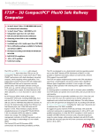
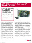
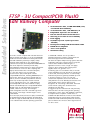
The F75P is a COTS computer with onboard functional
safety that unites three CPUs on one 3U CompactPCI®
PlusIO card. It makes Intel® Atom™ E6xx performance
with dual redundancy extremely compact, mainly
targeting railway applications. Two independent
Control Processors (CP) with independent DDR2 RAM and
Flash and a supervision structure provide safety:
with redundant software running on F75P, and with the
software instances on the two CPs comparing their
output, the board becomes a fail-silent subsystem,
i.e. it can shut down in case of a fatal fault.
Its I/O Processor (IOP) is built up like a classic
CompactPCI® CPU board, including DDR2 RAM, front
and rear I/O. The front connectors include VGA, two
USB 2.0, and two 100-Mbit (Fast) Ethernet channels.
At the rear, the board provides another four USB
2.0, two Fast Ethernet ports, one 3-Gbit SATA and
one PCI Express® x1 link. These interfaces comply
with the standardized pinout of CompactPCI® PlusIO
(PICMG 2.30). An onboard mSATA slot makes for
scalable, robust mass storage. The intelligent
board management controller of the IOP logs events
such as reset, overvoltage or undervoltage in a nonvolatile FRAM.
The Control (CP) and I/O Processors (IOP) communicate
via internal Ethernet links provided by an FPGA. While
the IOP also supports Windows®, the CPs are designed
to run a deterministic real-time operating system such
1
2x Intel® Atom™ E6xx, 512 MB DDR2 RAM (each)
for onboard dual redundancy
1x Intel® Atom™ E6xx, 1 GB DDR2 for I/O
Independent supervisors for each block
Fail-safe and fail-silent board architecture
Clustering of two F75P to raise availability
Event logging
Certifiable up to SIL 4 (with report from
TÜV SÜD)
Developed according to EN 50129 and IEC 61508
Full EN 50155 compliance
-40 to +85°C qualified
Conformal coating
as VxWorks® or PikeOS. It is also possible to
implement diversitary software on both kernels. All
three CPUs support Linux and VxWorks®.
The F75P can replace multiprocessing systems with CPU
redundancy and I/O by a small-footprint, low-power
solution that is flexible for different types of
application scenarios. It uses a single +5V supply
voltage to allow operation with external power
supplies that do not generate +3.3 V.
A clustering option is considered as well, to increase
system availability: two F75P boards can operate next
to each other, and can provide hot or cold stand-by.
F75P-based systems are generally certifiable up to SIL
4. Since the card has no voter of its own, the
software that implements and controls functional
safety behavior has to be added by the customer. The
safety features such as the CP supervisors are
designed to SIL 4 according to EN 50129. The board
comes with the "safety case" document and a
certificate from TÜV SÜD.
Its rugged set-up also make the F75P truly rail-ready:
with assets like conformal coating and an operating
temperature of -40 to +85°C with qualified components,
it is fully EN 50155 compliant. A 4-HP version is
available with RJ45 Ethernet connectors and a reduced
temperature range for system design, while another
standard card with 8 HP width provides the necessary
space for M12 front connectors and a larger heat sink
for -40 to +85°C.
®
F75P Data Sheet - 2012-10-05
Embedded Solutions
Technical Data
CPUs
n Three onboard processors
o Two Control Processors (CP)
o One I/O Processor (IOP)
n Intel® Atom™ E6xx Series
o 0.6 GHz to 1.6 GHz processor core frequency
o Three identical processors
o Please see Standard Configurations and Options below
for options and available standard versions.
n Chipset
o Intel® EG20T Platform Controller Hub (PCH)
o Implemented only once for I/O Processor
Memory
n 512 KB L2 cache integrated in E6xx for each processor
n Up to 1 GB SDRAM system memory to each of the Control
Processors (CP)
o Soldered
o DDR2
o 800 MHz memory bus frequency (800 MT/s data rate)
n Up to 2 GB SDRAM system memory to I/O Processor (IOP)
o Soldered
o DDR2
o 800 MHz memory bus frequency (800 MT/s data rate)
n 2 MB BIOS Flash
n 8 KB non-volatile FRAM connected to IOP for event logging
n mSATA disk slot
o Connected via one SATA channel
n Please see Standard Configurations and Options below for
options and available standard versions.
Mass Storage
n Serial ATA (SATA)
o One port for mSATA onboard devices
o One port for rear I/O
o SATA Revision 2.x support
o Transfer rates up to 300 MB/s (3 Gbit/s)
Graphics
n Integrated in E6xx processor
o 320 or 400 MHz graphics base frequency, depending on
processor type
o Maximum resolution: 1280 x 1024 pixels
n VGA connector at front panel
I/O
n USB
o Six USB 2.0 host ports
o Two Series A connectors at front panel
o Four ports via rear I/O on CompactPCI® J2
o OHCI and EHCI implementation
o Data rates up to 480 Mbit/s
2
n
n
Ethernet
o Four 10/100Base-T Ethernet channels
o Two channels via RJ45 or M12 connectors at front
panel, with status LEDs
o Two channels via rear I/O on CompactPCI® J2
PCI Express®
o One PCI Express® x1 link via rear I/O on CompactPCI® J2
o PCIe® 1.0a support
o Data rate up to 250 MB/s in each direction (2.5 Gbit/s
per lane)
Front Connections (Standard)
n VGA
n Two USB 2.0 (Series A)
n Two 10/100Base-T Ethernet (RJ45 or M12)
Rear I/O (PICMG 2.30)
n One SATA (3 Gb)
n Four USB 2.0
n Two 10/100Base-T Ethernet
n One PCI Express® x1 link
n Compatible with PICMG 2.30 CompactPCI® PlusIO
o 1PCI33/1PCIE2.5/1SATA3/4USB2/2ETH100
o Some pins are used for signals differing from the
PICMG 2.30 specification, e.g., for clustering.
However, these signals do not destroy or cause any
malfunction of a connected I/O board based on this
standard.
Event Logging
n Event history logged in non-volatile FRAM, e.g., reset,
overvoltage, undervoltage, excess temperature
n 256 entries possible
n Events are generated by board hardware or user application
Cluster Link
n Two F75P boards can be connected to form a cluster
n Cluster link interface based on RS422
o Accessible on CompactPCI® J2 rear I/O connector
o Bidirectional, full-duplex, differential interface
Miscellaneous
n Real-time clock with supercapacitor backup connected to
I/O Processor
n Three independent supervisors for Control Processors and
Inter-Communication FPGA
o Check for overvoltage, undervoltage, excess
temperature, internal errors of FPGA and CPUs, CPU und
FPGA clock
o Perform a range of self tests
o Watchdog
n Board Management Controller for I/O Processor
®
F75P Data Sheet - 2012-10-05
Embedded Solutions
Technical Data
n
n
Status LED at front panel
Reset button at front panel
CompactPCI® Bus
n Compliance with CompactPCI® Core Specification PICMG 2.0
R3.0
n System slot
n 32-bit/33-MHz PCI-to-PCI bridge
n V(I/O): +3.3 V (+5 V tolerant)
n Hot insertion and removal without damage
Busless Operation
n Board can be supplied with +5 V only, all other voltages
are generated on the board
n Backplane connectors used only for power supply
Electrical Specifications
n Supply voltage/power consumption:
o +5 V (-5%/+5%), tbd. A
Mechanical Specifications
n Dimensions: conforming to CompactPCI® specification for
3U boards
n Front panel: 4 HP or 8 HP with ejector
n Weight: tbd. g (incl. heat sink)
Environmental Specifications
n Temperature range (operation):
o -40..+50°C in 4 HP version (qualified components)
o -40..+85°C in 8 HP version (qualified components),
compliant with EN 50155, class Tx
o Conditions: airflow 1.5 m/s, typical power
dissipation: tbd.
n Temperature range (storage): -40..+85°C
n Relative humidity (operation): max. 95% non-condensing
n Relative humidity (storage): max. 95% non-condensing
n Altitude: -300 m to +3000 m
n Vibration (function): 1 m/s², 5 Hz - 150 Hz (EN 50155
(12.2.11) / EN 61373)
n Vibration (lifetime): 7.9 m/s², 5 Hz - 150 Hz (EN 50155
(12.2.11) / EN 61373)
n Shock: 50 m/s², 30 ms (EN 50155 (12.2.11) / EN 61373)
n Conformal coating (standard)
Configured for deterministic behavior, e.g.,
Hyper-Threading disabled, speed-step disabled, BIOS
interrupts disabled
o Board maintains safe state after a failure (factory
configuration)
Flammability
o PCB manufactured with a flammability rating of 94V-0
by UL recognized manufacturers
o
n
EMC Conformity
n When integrated into an EMC protected rack
n EN 50121-3-2 (tables 5 and 6) / EN 55011 (radio
disturbance)
n EN 50121-3-2 (table 9) / IEC 61000-4-6 (ESD)
n EN 50121-3-2 (table 9) / IEC 61000-4-3
(electromagnetic field immunity)
n EN 50121-3-2 (table 8) / IEC 61000-4-4 (burst)
n EN 50121-3-2 (table 8) / IEC 61000-4-6 (conducted
disturbances)
BIOS
n InsydeH2O™ UEFI Framework
Software Support
n I/O Processor
o Windows® 7
o Windows® Embedded Standard 7 (in preparation)
o Linux (in preparation)
o VxWorks® (on request)
n Control Processors
o Linux (in preparation)
o VxWorks® (in preparation)
o VxWorks®/Cert (on request)
o PikeOS (in preparation)
n For more information on supported operating system
versions and drivers see Software.
MTBF
n tbd. h @ 40°C according to IEC/TR 62380 (RDF 2000)
Safety
n Functional Safety
o Certifiable up to SIL 4 according to EN 50129 ("safety
case" document and certificate from TÜV SÜD available)
o Hazard rate for safety functions <= 1E-9 / h
3
®
F75P Data Sheet - 2012-10-05
Embedded Solutions
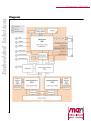
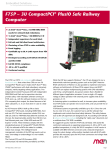
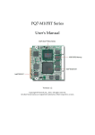
Diagram
4
®
F75P Data Sheet - 2012-10-05
Embedded Solutions
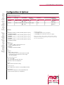
Configuration & Options
Standard Configurations
Article No.
CPU Type
02F075P00
02F075P01
System RAM
Ethernet
connectors
Front Panel
Conformal Coating Operating
Temperature
3x E680T, 1.6 GHz CPs: 512 MB each, RJ45
IOP: 1 GB
4 HP
Yes
-40..+50°C
qualified
3x E680T, 1.6 GHz CPs: 512 MB each, M12 (right)
IOP: 1 GB
8 HP
Yes
-40..+85°C
qualified
Options
CPU
n Intel® Atom™ E620T, 0.6 GHz, 320 MHz graphics frequency,
3.3 W TDP (estimated)
n Intel® Atom™ E640T, 1.1 GHz, 320 MHz graphics frequency,
3.6 W TDP
n Intel® Atom™ E660T, 1.3 GHz, 400 MHz graphics frequency,
3.6 W TDP
n Intel® Atom™ E680T, 1.6 GHz, 400 MHz graphics frequency,
4.5 W TDP (estimated)
Software Support
n VxWorks® for I/O Processor (on request)
n VxWorks®/Cert for Control Processors (on request)
Please note that some of these options may only be
available for large volumes. Please ask our sales staff
for more information.
Memory
n System RAM
o 512 MB or 1 GB for each Control Processor
o 1 GB or 2 GB for I/O Processor
n mSATA disk
o 0 MB up to maximum available
I/O
n Ethernet
o RJ45 or M12 connectors
o M12 connectors need a second front-panel slot (8 HP
total width) and can be placed to the left or right
side of the CPU PCB.
Operating Temperature
n -40..+50°C (4 HP)
n -40..+85°C (8 HP, with larger heat sink)
n Depends on heat sink configuration
Coating
n With or without conformal coating
Cooling Concept
n Also available with conduction cooling in MEN CCA frame
Restart Option
n Board can be configured to restart automatically after
entering safe state (by factory configuration)
5
®
F75P Data Sheet - 2012-10-05
Embedded Solutions
Ordering Information
Standard F75P Models
02F075P00
F75P, 3U CompactPCI® (PICMG 2.0) and
CompactPCI® PlusIO (PICMG 2.30) SBC, 3x
Intel® Atom™ E680T (1.6 GHz), 2x 512 MB, 1x
1 GB DDR2 DRAM, 4 HP, -40..+50°C qualified
02F075P01
F75P, 3U CompactPCI® (PICMG 2.0) and
CompactPCI® PlusIO (PICMG 2.30) SBC, 3x
Intel® Atom™ E680T (1.6 GHz), 2x 512 MB, 1x
1 GB DDR2 DRAM, 8 HP, Ethernet on the right
by 2x M12, -40..+85°C qualified
Related Hardware
08CT12-00
CompactPCI® PlusIO rear transition module
3U/80mm, 2 Ethernet, 4 USB, 4 SATA, 4 PCIe®
x1, -40°C..+85°C qualified
Memory
0751-0051
SSD mSATA, 8 GB, -40..+85°C
Systems & Card Cages
0701-0046
CompactPCI® 19" 4U/24HP desktop system for
3U cards, 3-slot 3U CompactPCI® backplane,
system slot right, 1U fan tray with 1 fan,
8 HP space for 1 pluggable PSU
0701-0056
CompactPCI® 19" 4U/84HP rack-mount
enclosure for 3U cards (vertical), 4+4-slot
3U CompactPCI® / CompactPCI® Serial hybrid
backplane, prepared for rear I/O, 250W
power supply wide range 90..264VAC on rear,
1U fan tray with 2 fans included, 0..+60°C
Documentation
Compare 3U CompactPCI® Serial CPU and I/O cards
For the most up-to-date ordering information and direct
links to other data sheets and downloads, see the F75P
online data sheet under » www.men.de.
6
®
F75P Data Sheet - 2012-10-05
Embedded Solutions
Contact Information
Germany
MEN Mikro Elektronik GmbH
Neuwieder Straße 3-7
90411 Nuremberg
Phone +49-911-99 33 5-0
Fax +49-911-99 33 5-901
E-mail [email protected]
www.men.de
France
MEN Mikro Elektronik SA
18, rue René Cassin
ZA de la Châtelaine
74240 Gaillard
Phone +33 (0) 450-955-312
Fax +33 (0) 450-955-211
E-mail [email protected]
www.men-france.fr
USA
MEN Micro, Inc.
24 North Main Street
Ambler, PA 19002
Phone (215) 542-9575
Fax (215) 542-9577
E-mail [email protected]
www.menmicro.com
The date of issue stated in this data sheet refers to the Technical Data only. Changes in ordering information given herein do not affect the date of issue.
All brand or product names are trademarks or registered trademarks of their respective holders.
MEN is not responsible for the results of any actions taken on the basis of information in the publication, nor for any error in or omission from the publication.
MEN expressly disclaims all and any liability and responsibility to any person, whether a reader of the publication or not, in respect of anything, and of the
consequences of anything, done or omitted to be done by any such person in reliance, whether wholly or partially, on the whole or any part of the contents of the publication.
The correct function of MEN products in mission-critical and life-critical applications is limited to the environmental specification given for each product in the technical
user manual.The correct function of MEN products under extended environmental conditions is limited to the individual requirement specification and subsequent
validation documents for each product for the applicable use case and has to be agreed upon in writing by MEN and the customer.Should the customer purchase or use
MEN products for any unintended or unauthorized application, the customer shall indemnify and hold MEN and its officers, employees, subsidiaries, affiliates, and distributors
harmless against all claims, costs, damages, and expenses, and reasonable attorney fees arising out of, directly or indirectly, any claim or personal injury or death associated
with such unintended or unauthorized use, even if such claim alleges that MEN was negligent regarding the design or manufacture of the part.
In no case is MEN liable for the correct function of the technical installation where MEN products are a part of.
Copyright © 2012 MEN Mikro Elektronik GmbH. All rights reserved.
7
®