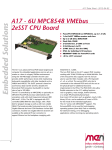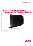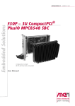
1
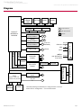
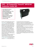
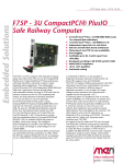
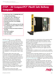
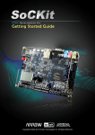
Embedded Solutions
for Transportation and Industrial Markets
www.men.de/products/02F050P.html
F50P – 3U CompactPCI® PlusIO PowerPC®
MPC8548 CPU Board
n 32-bit CompactPCI® and PICMG 2.30 PlusIO
n 8 HP or 12 HP with front I/O
n MPC8548 (or MPC8543), up to 1.5 GHz
n Up to 2 GB (ECC) DDR2 SDRAM
n Up to 128 KB FRAM, 2 MB SRAM
n Up to 16 GB SSD Flash
n Standard front I/O: 2 Gb Ethernet, 2 USB
n Standard rear I/O: 4 USB, 2 SATA
n FPGA for user-defined I/O functions
(option)
n MENMON BIOS for PowerPC® cards
n -40 to +70°C (8 HP) (screened)
The F50P is a versatile, rugged PowerPC® based singleboard computer for embedded applications. It is
controlled by an MPC8548, or optionally an MPC8543
PowerPC® processor (alternatively with encryption unit)
with clock frequencies between 800 MHz and 1.5 GHz.
The SBC is equipped with ECC-controlled, soldered-on
DDR2 RAM for data storage, with up to 16 GB of solidstate Flash disk for program storage as well as industrial
FRAM and SRAM.
The CPU card provides up to three Gigabit Ethernet
channels, six USB ports, up to two SATA interfaces and
up to 64 user-definable I/O lines controlled by an
optional onboard FPGA. These interfaces can be
combined in many variations and are available at the
front or at the rear using the board's J2 connector. The
J2 pin assignment and connector type are in
compliance with the PICMG 2.30 CompactPCI® PlusIO
standard - the migration path towards CompactPCI®
Serial. Two USB and two RJ45 Ethernet connectors are
already provided at the front panel, and space is left for
an optional VGA connector.
The large FPGA on the F50P allows to add additional
user-defined functions such as graphics, touch, serial
interfaces, fieldbus controllers, binary I/O etc. for the
needs of the individual application in an extremely
F50P Data Sheet / 2014-11-11
flexible way. Before boot-up of the system, the FPGA is loaded from
boot Flash. Updates of the FPGA contents can be made inside the boot
Flash during operation. If the FPGA is assembled, the card needs an
extra 4 HP in front panel space.
Equipped with a PCI-bridge chip, the F50P offers a full CompactPCI®
interface (system slot functionality) for reliable system expansion. Apart
from that, the F50P can also be used as a busless, stand-alone board,
with power supply from the backplane.
Being designed for operation in a conduction or convection cooled
environment, the F50P provides flexibility also in its cooling concept. Its
firmly plugged-on CPU module is embedded in a covered frame. This
ensures EMC protection and allows efficient conductive cooling for the
F50C model, which is also available by standard. For air cooling, the
F50P version comes with a tailor-made heat sink on top of the cover,
requiring an 8-HP front panel, for an extended temperature range of -40
to +70°C. The soldered components on the F50P withstand shock and
vibration, and the board design is optimized for conformal coating.
The F50P comes with MENMON support. This firmware/BIOS can be
used for bootstrapping operating systems (from disk, Flash or network),
for hardware testing, or for debugging applications without running any
operating system.
Page 1
Embedded Solutions
for Transportation and Industrial Markets
www.men.de/products/02F050P.html
Diagram
Boot Flash
EEPROM
RTC
FRAM
SRAM
Supervisor
I²C
PowerPC®
MPC8548 or
MPC8543
Ethernet
10/100/1000Base-T
Ethernet
10/100/1000Base-T
Ethernet
10/100/1000Base-T
F
Front connector
R
Rear I/O connector
Options
F R
F R
(only with
R MPC8548)
0/1/2/3
Ethernet
4
USB
UART-to-USB
PCI
Bus
66
PCI
Bus
33
PCI-to-USB
(5 ports)
F
(client)
F
R
0/1/2
SATA
and/or: up to 64
user-defined I/O
from FPGA
CompactPCI® J2
System
SDRAM
DDR2
R
(MPC8543)
SSD Flash
R
PCIe x1
VGA (with optional
FPGA
FPGA)
(option, adds 4 HP,
up to 64 user I/O lines)
up to 64
F
CompactPCI® J1
SATA-to-PATA
PCIe-to-PCI Bridge
(MPC8548)
PCI-to-SATA
(3 ports)
R
Option: Busless
SDRAM
Additional
F50P Data Sheet / 2014-11-11
Flash
The F50P provides great flexibility for routing functions to rear I/O.
Please refer to “Configuration...“ for more information.
Page 2
Embedded Solutions
for Transportation and Industrial Markets
www.men.de/products/02F050P.html
Technical Data
CPU
n
PowerPC® PowerQUICC™ III MPC8548, MPC8548E, MPC8543 or MPC8543E
o 800 MHz up to 1.5 GHz
o Please see Standard Configurations for available standard versions.
®
o e500 PowerPC core with MMU and double-precision embedded scalar and vector floating-point APU
o Integrated Northbridge and Southbridge
Memory
n
2 x 32 KB L1 data and instruction cache, 512 KB / 256 KB L2 cache integrated in MPC8548/MPC8543
Up to 2 GB SDRAM system memory
o Soldered
o DDR2 with or without ECC
o Up to 300 MHz memory bus frequency, depending on CPU
Up to 16 GB soldered Flash disk (SSD solid state disk)
Up to 32 MB additional DDR2 SDRAM, FPGA-controlled, e.g. for video data
16 MB boot Flash
2 MB non-volatile SRAM
o With GoldCap backup
128 KB non-volatile FRAM
Serial EEPROM 4 kbits for factory settings
n
n
n
n
n
n
n
Mass Storage
n
n
Graphics
n
n
I/O
n
n
n
n
Front Connections (Standard)
n
n
n
F50P Data Sheet / 2014-11-11
Parallel IDE (PATA)
o Up to 16 GB soldered ATA Flash disk (SSD solid state disk)
Serial ATA (SATA)
o Up to two ports via rear I/O J2
o Transfer rates up to 150 MB/s (1.5 Gbit/s)
o Via PCI-to-SATA bridge
o See interface configuration matrix showing possible I/O combinations (PDF)
FPGA-controlled (optional)
VGA connector prepared at front panel
USB (host)
o Five USB 2.0 host ports
o One series A connector at front panel
o Four ports via rear I/O J2
o OHCI and EHCI implementation
o Data rates up to 480 Mbit/s
USB (client)
o One USB client port on series A connector at front panel
o Via UART-to-USB converter
o Data rates up to 115.2 kbit/s
o 16-byte transmit/receive buffer
o Handshake lines: none
Ethernet
o Up to three 10/100/1000Base-T Ethernet channels with MPC8548/E (two channels with MPC8543/E)
o Two RJ45 connectors at front panel
o Two front-panel LEDs for channels for LAN link, activity status and connection speed
o All three possible also via rear I/O J2 (Note: requires additional Ethernet transformers on rear I/O board
or backplane.)
o See interface configuration matrix showing possible I/O combinations (PDF)
User-defined I/O
o FPGA-controlled (optional)
o Up to 64 I/O lines
o Connection via rear I/O J2
o See interface configuration matrix showing possible I/O combinations (PDF)
One USB 2.0 host (Series A)
One USB client (Series A)
Two Ethernet (RJ45)
Page 3
Embedded Solutions
for Transportation and Industrial Markets
www.men.de/products/02F050P.html
Technical Data
Rear I/O
n
n
n
n
n
FPGA
n
n
Miscellaneous
n
n
n
n
CompactPCI® Bus
n
n
n
n
Busless Operation
n
n
Four USB 2.0
Up to three 1000Base-T Ethernet
Up to two SATA
Up to 64 I/O lines with optional FPGA
o Reduces Ethernet/SATA interfaces
o See interface configuration matrix showing possible I/O combinations (PDF)
Standard version compatible with PICMG 2.30 CompactPCI® PlusIO
o Two SATA
o Four USB 2.0
o 1PCI33/0PCIE/2SATA1.5/4USB2/0ETH
The FPGA offers the possibility to add customized I/O functionality. See Options
Standard: FPGA not assembled
Real-time clock with GoldCap backup
Temperature sensor, power supervision and watchdog
Status LED at the front
Reset button
Compliance with CompactPCI® Core Specification PICMG 2.0 R3.0
System slot
32-bit/32-MHz PCIe®-to-PCI bridge
V(I/O): +3.3 V (+5 V tolerant)
Board can be supplied with +5 V, +3.3 V and +12 V from backplane, all other voltages are generated on
the board
Backplane J1 connector used only for power supply
Electrical Specifications
n
Supply voltage/power consumption:
o +5 V (-3%/+5%), 800 mA approx.
o +3.3 V (-3%/+5%), 350 mA approx.
o ±12 V (-5%/+5%), 1 A approx.
Mechanical Specifications
n
Dimensions: conforming to CompactPCI® specification for 3U boards
Front panel:
o 8 HP without FPGA
o 12 HP with FPGA
o See also F50P front panel diagram
Weight: 626 g
n
n
Environmental Specifications
n
Temperature range (operation):
o -40..+70°C (screened)
o 0..+60°C (screened, with 16 GB SSD Flash disk)
o Airflow: min. 1.0 m/s
o Conduction cooled variety F50C also available
Temperature range (storage): -40..+85°C
Relative humidity (operation): max. 95% non-condensing
Relative humidity (storage): max. 95% non-condensing
Altitude: -300 m to + 3,000 m
Shock: 15 g, 11 ms
Bump: 10 g, 16 ms
Vibration (sinusoidal): 1 g, 10..150 Hz
Conformal coating on request
MTBF
n
162,822 h @ 40°C according to IEC/TR 62380 (RDF 2000)
Safety
n
PCB manufactured with a flammability rating of 94V-0 by UL recognized manufacturers
EMC
n
Tested according to EN 55022 (radio disturbance), IEC1000-4-2 (ESD) and IEC1000-4-4 (burst)
BIOS
n
MENMON
n
n
n
n
n
n
n
n
F50P Data Sheet / 2014-11-11
Page 4
Embedded Solutions
for Transportation and Industrial Markets
www.men.de/products/02F050P.html
Technical Data
Software Support
n
n
n
n
n
n
Linux
VxWorks®
QNX® (on request; support of the FPU is currently not provided by QNX®)
INTEGRITY® (Green Hills® Software) support available. Please contact Green Hills® for further information.
OS-9® (on request)
For more information on supported operating system versions and drivers see Downloads.
Configuration & Options
Standard Configurations
Article No.
CPU Type
System
RAM /
FRAM
SSD
Front I/O
Rear I/O
FPGA
Front
Panel
Op. Temp.
Cooling
02F050P00
MPC8548,
1.33 GHz
512 MB
ECC / 128
KB
2GB
2 USB / 2
ETH
4 USB / 2
SATA
No
8 HP
-40..+70°C
Convection
02F050C00
MPC8548,
1.33 GHz
512 MB
ECC / 128
KB
2GB
1 USB
client
4 USB / 2
ETH / 2
SATA / 14
GPIO / 4
UARTs
Yes
9 HP
-40..+85°C
Conduction
Options
CPU
n
n
n
Memory
n
n
n
n
I/O
n
n
n
n
n
F50P Data Sheet / 2014-11-11
Several PowerQUICC™ III types with different clock frequencies
MPC8548 or MPC8548E
o 1 GHz, 1.2 GHz, 1.33 GHz or 1.5 GHz
MPC8543 or MPC8543E
o 800 MHz or 1 GHz
System RAM
o 512 MB, 1 GB or 2 GB
o With or without ECC
Flash Disk
o 2 GB, 4 GB, 8 GB or 16 GB
o Please note that the 16 GB Flash disk component only supports a temperature range of 0..+60°C!
FRAM
o 0 KB or 128 KB
Additional SDRAM
o 0 MB or 32 MB
o With optional FPGA
See interface configuration matrix showing possible I/O combinations (PDF)
VGA at front (with optional FPGA)
Ethernet
o Up to two channels at front
o Up to three channels at rear
o Only two channels total with MPC8543
SATA
o Up to two channels at rear
Up to 64 user-defined I/O lines
o With optional FPGA, see below
o Reduces number of Ethernet/SATA channels
Page 5
Embedded Solutions
for Transportation and Industrial Markets
www.men.de/products/02F050P.html
Configuration & Options
FPGA
n
n
n
n
n
Cooling concept
n
n
The optional onboard FPGA offers the possibility to implement customized I/O functionality.
FPGA Altera® Arria® GX AGX35C
o 33,520 logic elements
o 1,348,416 total memory bits
®
o Connected to CPU via PCI Express x1 link
Connection
o Available pin count: 64 pins
o Functions available via rear I/O J2 connector
Please note that the FPGA expands the board's width by 4 HP, to 12 HP!
o See also F50P front panel diagram
You can find more information on our web page "User I/O in FPGA"
-40..+70°C on 8 HP with heat sink (without FPGA) for convection cooling
Conduction cooled variety F50C also available, for -40..+85°C
Please note that some of these options may only be available for large volumes. Please ask our sales staff for more information.
F50P Data Sheet / 2014-11-11
Page 6
Embedded Solutions
for Transportation and Industrial Markets
www.men.de/products/02F050P.html
Ordering Information
Standard F50P Models
02F050P00
MPC8548, 1.33 GHz, 2 GB SSD Flash, 512 MB DDR2 RAM, 2 MB SRAM, 128 KB FRAM,
front I/O and PICMG 2.30 rear I/O (2 SATA, 4 USB), 8 HP, no FPGA, -40..+70°C screened
Related Hardware
02F050C00
MPC8548, 1.33 GHz, 2 GB SSD Flash, 512 MB DDR2 RAM, 2 MB SRAM, 128 KB FRAM,
FPGA, rear I/O (2 GbE, 4 USB, 2 SATA, 14 GPIO, 4 UARTs), 9 HP, -40..+85°C Tcase
screened - conduction cooled board within CCA frame
08CT12-00
CompactPCI® PlusIO rear transition module 3U/80mm, 2 Ethernet, 4 USB, 4 SATA, 4
PCIe® x1, -40°C..+85°C qualified
0701-0046
CompactPCI® 19" 4U/24HP desktop system for 3U cards, 3-slot 3U CompactPCI®
backplane, system slot right, 1U fan tray with 1 fan, 8 HP space for 1 pluggable PSU
0701-0056
CompactPCI® 19" 4U/84HP rack-mount enclosure for 3U cards (vertical), 4+4-slot 3U
CompactPCI® / CompactPCI® Serial hybrid backplane, prepared for rear I/O, 250W
power supply wide range 90..264VAC on rear, 1U fan tray with 2 fans included, 0..+60°C
Systems & Card Cages
MEN delivers turn-key systems completely installed (hardware, operating system, accessories), wired and
tested. Different rack sizes, power supplies and backplanes on request.
For details please contact your local sales representative.
Software: Linux
This product is designed to work under Linux. See below for all available separate software packages.
10EM09-91
Software: VxWorks®
General Linux BSP for A17, EM9, EM9A, EK9, F50C, F50P and XM50
This product is designed to work under VxWorks®. For details regarding supported/unsupported board
functions please refer to the corresponding software data sheets.
10EM09-60
VxWorks® 6.4/6.5 BSP (MEN) for A17, EK9, EM9, EM9A, F50C, F50P and XM50
10EM09-61
VxWorks® 6.9 BSP (MEN) for A17, EK9, EM9, EM9A, F50C, F50P and XM50
Software: INTEGRITY®
This product is designed to work under the INTEGRITY® RTOS from Green Hills® Software. An INTEGRITY®
Board Support Package for this board is provided by Green Hills® Software. For more information and
product support please contact Green Hills® Software (www.ghs.com).
Software: Firmware/BIOS
MENMON is MEN's firmware/BIOS for PowerPC® platforms.
14XM50-00
Software: Miscellaneous
MENMON (Firmware) for XM50, F50C and F50P (object code)
A Windows® USB2UART driver from FTDI is available for XM50, XM51 and F50P/F50C Windows® hosts.
More info & downloads
For operating systems not mentioned here contact MEN sales.
Documentation
Compare Chart 3U CompactPCI® Serial CPU and I/O cards » Download
Compare Chart 3U CompactPCI® / PlusIO CPU cards » Download
Compare Chart 3U CompactPCI® / PlusIO peripheral cards » Download
Compare Chart 3U CompactPCI® / PlusIO extension cards » Download
20F050P00
F50P Data Sheet / 2014-11-11
F50P User Manual
Page 7
Embedded Solutions
for Transportation and Industrial Markets
www.men.de/products/02F050P.html
Contact Information
Germany
France
USA
MEN Mikro Elektronik GmbH
Neuwieder Straße 3-7
90411 Nuremberg
Phone +49-911-99 33 5-0
Fax +49-911-99 33 5-901
MEN Mikro Elektronik SAS
18, rue René Cassin
ZA de la Châtelaine
74240 Gaillard
Phone +33 (0) 450-955-312
Fax +33 (0) 450-955-211
MEN Micro Inc.
860 Penllyn Blue Bell Pike
Blue Bell, PA 19422
Phone (215) 542-9575
Fax (215) 542-9577
[email protected]
www.men.de
[email protected]
www.men-france.fr
[email protected]
www.menmicro.com
The date of issue stated in this data sheet refers to the Technical Data only. Changes in ordering information given herein do not affect the date of issue. All brand or product names are
trademarks or registered trademarks of their respective holders.
MEN is not responsible for the results of any actions taken on the basis of information in the publication, nor for any error in or omission from the publication.
MEN expressly disclaims all and any liability and responsibility to any person, whether a reader of the publication or not, in respect of anything, and of the consequences of anything,
done or omitted to be done by any such person in reliance, whether wholly or partially, on the whole or any part of the contents of the publication.
The correct function of MEN products in mission-critical and life-critical applications is limited to the environmental specification given for each product in the technical user manual.The
correct function of MEN products under extended environmental conditions is limited to the individual requirement specification and subsequent validation documents for each product
for the applicable use case and has to be agreed upon in writing by MEN and the customer.Should the customer purchase or use MEN products for any unintended or unauthorized
application, the customer shall indemnify and hold MEN and its officers, employees, subsidiaries, affiliates, and distributors harmless against all claims, costs, damages, and expenses,
and reasonable attorney fees arising out of, directly or indirectly, any claim or personal injury or death associated with such unintended or unauthorized use, even if such claim alleges
that MEN was negligent regarding the design or manufacture of the part.
In no case is MEN liable for the correct function of the technical installation where MEN products are a part of.
Copyright © 2015 MEN Mikro Elektronik GmbH. All rights reserved.
F50P Data Sheet / 2014-11-11
Page 8